Producten
-

Elektor Digital Elektor November/December 2021 (PDF)
BEELDVERWERKING MET DE NVIDIA JETSON NANO (DEEL 2)Beeldherkenning met Edge Impulse NIEUWS VAN ELEKTOR JUMPSTARTERNieuwe campagnes EEN OPEN SOURCE-PLATFORM VOOR GPS-TRACKINGMet Traccar voertuigen volgen zonder gebruik te maken van een cloudserver JOY-IT LCR-T7 MULTIFUNCTIONELE TESTERVoor passieve componenten, discrete halfgeleiders en IR RUISSYNTHESIZERVan ruis naar muziek met de PRBSynth1 ALLE BEGIN......speelt verder met de spoel KENNISMAKING MET NEURONEN IN NEURALE NETWERKEN (DEEL 2)Logische Neuronen BEVEILIGINGSPROBLEMEN? BESTRIJD VUUR MET VUUR!Met flitslampje beveiligde analoge geheugenuitbreiding voor de verzendbox met manipulatie-indicatie LCR METER POSTER BLUETOOTH-BAKENS IN DE PRAKTIJKindoor-plaatsbepaling PROGRAMMEREN IN C OP DE RASPBERRY PICommunicatie via WiFi (een hoofdstuk als voorbeeld) EMC PRE-COMPLIANCE TEST VOOR UW DC-GEVOED PROJECT (DEEL 2)De hardware en het gebruik ervan KENNISMAKING MET DE PARALLAX PROPELLER 2 (DEEL 5)Smart Pin-Functie MODBUS VIA WLAN (DEEL 1)Hardware en programmering OOST WEST LAB BEST... waar de Junior Computer weer tot leven is gewekt BOUW ZELF EEN NAUWKEURIGE KALIBRATOR-10 V tot +10 V, 0 tot 40 mA, 0,001% REVIEW: ARDUINO NANO RP2040 CONNECTRaspberry Pi RP2040 + WiFi + Bluetooth DE FYSIEKE KANT VAN KUNSTMATIGE INTELLIGENTIE PROJECT 2.0Correcties, Updates en Brieven van lezers MAAK GUI'S MET PYTHONIntroductie in guizero CO2-METER-BOUWKIT VOOR IN DE KLASEen ESP8266-project van de University of Applied Sciences Aachen NOSTALGISCHE MK484 MW/LW-RADIO...Altijd leuk om te bouwen! ELEKTOR @ 60Laat er licht zijn! HEXADOKUThe Original Elektorized Sudoku
€ 9,95
-

Elektor Digital Elektor November/December 2022 (PDF)
Elektor GREEN en GOLD leden kunnen deze uitgave hier downloaden.Nog geen lid? Klik hier om een lidmaatschap af te sluiten. High-end uit het Elektor-lab Fortissimo-100 high-end versterkervolledig symmetrische audio-eindtrap levert 100/190 W Controleer de frequentie van afgestemde kringen en kristallen Printen ontwerpentips en trucs Solderen – nou en?moderne soldeertechnologie nader bekeken Bluetooth-garagedeurbediening met geringe latentiemet korte BLE-berichten vanaf een smartphone Ideale diode-controllerdiodeschakelingen met geringe vermogensdissipatie LED-slingers met ESP32 en FreeRTOSknipperen dat het een lieve lust is Alle begin......zenert er vrolijk op los FM/DAB+ ontvangerhet beste van twee werelden Uit het leven gegrepenelektronica obscura De oorzaak van software-bugs draadloos opsporencirculaire buffer en webserver op de ESP32 Heeft Covid de innovatie gestimuleerd?innovatieve componenten en oplossingen uit 2022 Ersa i-CON TRACEhet IoT-soldeerstation voor makers Elektor Infographics Wat moeten we met al die computers? Aansturing van het e-paper display van Ynvisible InnoFaith: innovatie en nog eens innovatievraaggesprek met Walter Arkesteijn Industriële automatiseringeenvoudige en schaalbare IoT-retrofitting Reed-relaisvreemde onderdelen Low-profile lineaire connectorenvereenvoudigen multisignaal-databeheer Slim – Innovatief – KosteneffectiefGateMate FPGA’s worden ontwikkeld en geproduceerd in Duitsland Tools voor de ontwikkeling van goedkope sensoren Polyfusesvreemde onderdelen Geïsoleerde analoge uitgang voor Arduino Uno Oost West Lab Best...ontdekt de Theremin electronica fast forward 2022 – powered by Elektorde deelnemers en het programma Radiorichtingzoekerspoor verloren weersensoren op Schat de interne ruis van een ICeen eenvoudige methode Ethiek in actiepowered by WEEF Zonder ethiek geen duurzaam ondernemenvraaggesprek met professor Stefan Heinemann De WEEF Index 2023 Filtersoftwareontwerp-tools voor analoge filters TV-B-Gone!...of tenminste TV tabee Meting van de luchtkwaliteitop basis van de RP2040 elekterminal Snelstart met Python 3voorbeeldhoofdstuk: digitale beeldbewerking en de Wand-bibliotheek SOLARPUNKeen mooiere toekomst in het verschiet Hexadoku
€ 9,95
-

Elektor Digital Elektor November/December 2023 (PDF)
Elektor GREEN en GOLD leden kunnen deze uitgave hier downloaden.Nog geen lid? Klik hier om een lidmaatschap af te sluiten. De Raspberry Pi 5veel beter dan zijn voorganger AI in het elektronicalabontwerpen, componenten zoeken en programmeren Arduino Nano-golfvormgeneratorNano + code = functiegenerator Kerstslinger op zonne-energiemilieuvriendelijke oplossing voor op het balkon USB-killer-detectorvoorkomen is beter Een eenvoudige behuizing CNC’enmet Autodesk Fusion 360 voor persoonlijk gebruik Printen in geringe aantallen producerenmet en zonder assemblage IoT-simulatie vereenvoudigd met Wokwiontwikkelaar Uri Shaked over ontwerp, software en meer Een gids voor puristisch programmeren (deel 3)CMSIS-headers, automatisch testen en een webserver LoRa, een Zwitsers zakmesdeel 2: de hard- en software MEMS-microfoonontwerp en constructie Eerst proberen, dan solderengratis simulatie- en 3D-ontwerptools Nieuwe tools van Microchip!PICkit 5 en MPLAB ICD 5 nu verkrijgbaar! Snelle prototypen van flexibele, rekbare elektronicahoe de Voltera NOVA innovatie bij wearables versnelt Galvanische isolatiefototransistor-optocouplers succesvol gebruiken De complexe of de Anybus-oplossing?embedded industrieel ethernet in twee dagen in plaats van maanden De essentiële DFM-checklistontwerpen voor productie – hoe doe je dat? Filamenten voor 3D-printensoorten, kenmerken en gebruik bij prototyping Specialisten voor effectieve signaalanalyse van de ELF- tot de EHF-bandde nieuwste real-time SPECTRAN® V6 serie spectrumanalyzers van Aaronia Uitdagingen van DFM-analyse voor flex- en rigid-flex-ontwerpen Een SMT-productielijn installeren Elektor infographicsprototyping en productie Een revolutie voor de industriede opkomst van autonome mobiele robots Gemaakt voor groteuitdagingenRohde & Schwarz voegt achtkanaals R&S MXO 5 toe aan volgende generatie oscilloscopen Alle begin......versterkt verschillen Mini-reflowplaatvoor assemblage of reparatie van kleine SMD-schakelingen Begin niet met een prototype – begin met een pretotype!kijk of er wel een markt is voor je product voordat je de soldeerbout warmstookt 2023: een AI-odysseehulp bij het ontwerp van een tastbaar project Brussel innoveertsteun voor deep tech
€ 9,95
-

Elektor Digital Elektor November/December 2024 (PDF)
Elektor GREEN en GOLD leden kunnen deze uitgave hier downloaden. Nog geen lid? Klik hier om een lidmaatschap af te sluiten. Audio DSP FX Processor Boarddeel 1: eigenschappen en ontwerp 50 jaar Elektor in het Engels KiCad 8belangrijkste nieuwe en vernieuwde functies Elektor @ elektronica 2024electronica Fast Forward 2024, Experts on Stage, Influencer Forums, Live Elektor Lab Talk Shows en meer Elektor MultiCalculator KitArduino-gebaseerde DHZ-calculator voor elektronici Goedkope GNSS RTK-systemenmet centimeter-nauwkeurigheid Printlayout en veiligheidtips voor een veilig en duurzaam ontwerp van uw printen Opamp-testervoor audio en andere toepassingen Project-update #4: ESP32-gebaseerde energiemeterenergiemonitoring met MQTT Real-time spectrumanalyzer met golfgeleider-technologie en multi-interface PC’sAaronia introduceert nieuw productsegment en presenteert eerste prototypes op electronica in München SMT-spoelenspoelen en ferrieten – selectie gemakkelijk gemaakt EMC-conformiteit bereiken met EMI-afscherming De perfecte tool voor elke elektronicaliefhebbereindeloze mogelijkheden met Red Pitaya en 1.000+ Click Boards™ HDI in het middeneen nieuwe kosteneffectieve PCB-poolingservice voor kleine BGA’s Uitdagingen van DFM-analyse voor flex- en rigid-flex-ontwerpen Open source-toolsantennesimulator, componentenbeheer, rekenmachine en meer Elektor infographicprototyping en productie Uit het leven gegrepenmicrotechnofobie 3D-kerstboomdriedimensionale print met een goedkope 32 bit-microcontroller Alle begin......houdt nog lang niet op(amp)! Autonome sensor-node (project-update #1)RTC en voedingsschakelaar 2024: een AI-odysseeeen terugblik op de toekomst LED-displays met de MAX7219aan de slag met een grandioze chip Project 2.0correcties, updates en brieven van lezers Vibrotactiele handschoenendoorbraak voor Parkinson-patiënten
€ 9,95
-

Elektor November/December 2025 (NL)
Elektor GREEN en GOLD leden kunnen deze uitgave hier downloaden. Nog geen lid? Klik hier om een lidmaatschap af te sluiten. Relio v1.0 – Aanwezigheidsdetectie en afstandsbedieningEen smart controller met Matter-functionaliteit voor AC-apparaten Betere printplaten ontwerpenEen praktische gids voor professionals en makers KiCad 9De belangrijkste nieuwe en verbeterde functies Precisie pico-ampèremeter (1)Met curvetracer-functionaliteit tot in het pA-bereik! Kerstster 2025soldeer de sterren van de hemel! 100mV-doorgangstester Wie verlegt de grenzen van de Europese elektronica?Bedrijven om in het oog te houden Productronica 2025: Wat is er nieuw in de ontwikkeling en productie van elektronica Automatisering om reshoring van productie, invoerheffingen en tekorten aan arbeidskrachten aan te pakken Meer dan toekomstbestendigCirculariteit in elektronica Passieve componentenVerliesarme inductoren voor hoogrendements DC/DC-converters Hoe desktopmachines de printplaatproductie toegankelijker maken Alle begin......heeft voeding nodig Uit het leven gegrepenKnopjeskoorts Soldeertechniek in 2025Praktische soldeertips rechtstreeks van de werkbank SimulIDEEen alles-in-één tool voor circuit-prototyping 2025: Een AI OdysseyVan autocomplete tot collega Wordy Christmas TreeEen feestelijk elektronica-project met een taalkundig tintje Err-lectronicsCorrecties, updates en lezersbrieven Analoge pipeline-vervormingEen fraai audio-effect voor gitaren en andere instrumenten ESP32 audiotransceiver-board (deel 3)Stereotransmissie en dual-radio
€ 15,95
-

Elektor Digital Elektor November/December 2025 (PDF) NL
Elektor GREEN en GOLD leden kunnen deze uitgave hier downloaden. Nog geen lid? Klik hier om een lidmaatschap af te sluiten. Relio v1.0 – Aanwezigheidsdetectie en afstandsbedieningEen smart controller met Matter-functionaliteit voor AC-apparaten Betere printplaten ontwerpenEen praktische gids voor professionals en makers KiCad 9De belangrijkste nieuwe en verbeterde functies Precisie pico-ampèremeter (1)Met curvetracer-functionaliteit tot in het pA-bereik! Kerstster 2025soldeer de sterren van de hemel! 100mV-doorgangstester Wie verlegt de grenzen van de Europese elektronica?Bedrijven om in het oog te houden Productronica 2025: Wat is er nieuw in de ontwikkeling en productie van elektronica Automatisering om reshoring van productie, invoerheffingen en tekorten aan arbeidskrachten aan te pakken Meer dan toekomstbestendigCirculariteit in elektronica Passieve componentenVerliesarme inductoren voor hoogrendements DC/DC-converters Hoe desktopmachines de printplaatproductie toegankelijker maken Alle begin......heeft voeding nodig Uit het leven gegrepenKnopjeskoorts Soldeertechniek in 2025Praktische soldeertips rechtstreeks van de werkbank SimulIDEEen alles-in-één tool voor circuit-prototyping 2025: Een AI OdysseyVan autocomplete tot collega Wordy Christmas TreeEen feestelijk elektronica-project met een taalkundig tintje Err-lectronicsCorrecties, updates en lezersbrieven Analoge pipeline-vervormingEen fraai audio-effect voor gitaren en andere instrumenten ESP32 audiotransceiver-board (deel 3)Stereotransmissie en dual-radio
€ 9,95
-

Elektor Digital Elektor Novembre/Décembre 2024 (PDF)
Le téléchargement intégral de ce numéro est disponible pour nos membres GOLD et GREEN sur le site Elektor Magazine ! Pas encore membre ? Cliquez ici. Prototypage, production et composants ! carte processeur Audio DSP FXpartie 1 : caractéristiques et conception 50 ans d'Elektor en anglais KiCad 8nouvelles et dernières caractéristiques Elektor @ electronica 2024electronica Fast Forward 2024, des experts sur scène, des forums d'influenceurs, des talk-shows Elektor Lab en direct, et plus encore kit MultiCalculator d'ElektorUn kit de calculatrice basé sur Arduino pour l'électronique systèmes GNSS RTK à faible coûtavec un degré de précision de l'ordre du centimètre routage des Circuits Imprimés et sécuritéConseils pour une conception sure et fiable de vos cartes électroniques testeur d'ampli-oppour les applications audio et autres mise à jour du projet #4 : compteur d'énergie ESP32surveiller l'énergie avec MQTT analyseur de spectre temps-réel à technologie guide d’onde et PC à interfaces multiplesAaronia introduit une nouvelle ligne de produit et présente ses premiers prototypes au salon Electronica de Munich inductances SMTbobines et ferrites – un choix simplifié utilisation d’un blindage EMI pour assurer la conformité à la compatibilité électromagnétique l'outil ultime pour tous les passionnés d’électroniqueDébloquez des possibilités infinies avec Red Pitaya et plus de 1000 Click Boards™ HDI au milieuUn nouveau service PCB-pooling rentable pour des petits BGA défis de l'analyse DFM pour les circuits flexibles et flexibles-rigides outils open-sourcesimulateur d'antennes, gestion des composants, calculatrice, et bien plus Infographie : prototypage et production sur le vifmicrotechnophobie : c’est grave, docteur ? arbre de Noël 3Dcircuit imprimé 3D avec un microcontrôleur 32 bits peu coûteux démarrer en électronique......on continue avec l'ampli-op ! nœud de capteurs autonome (mise à jour du projet #1)Reducing Idle Power Consumption with External RTC and Power Switch 2024 : l'odyssée de l'IAUn regard sur l'avenir afficheurs LED avec le MAX7219Une méthode pratique pour une excellente puce projet 2.0Corrections, mises à jour et courrier des lecteurs gants vibro-tactilesune avancée pour les patients de Parkinson
€ 10,95
-

Elektor Novembre/Décembre 2025 (FR)
Le téléchargement intégral de ce numéro est disponible pour nos membres GOLD et GREEN sur le site Elektor Magazine ! Pas encore membre ? Cliquez ici. Relio v1.0 – détection de présence et contrôle à distanceUn contrôleur intelligent pour appareils électriques compatible Matter concevoir de meilleurs circuits imprimésUn guide pratique pour les professionnels et les makers KiCad 9Nouvelles fonctionnalités et mises à jour picoampèremètre de précision (1)Traceur de courbes jusqu’à la gamme des pA ! étoile de Noël 2025Fabriquer votre étoile testeur de continuité 100 mV l’innovation électronique en EuropeLes entreprises à suivre de près productronica 2025 : quoi de neuf dans le développement et la production électroniques l’automatisation face aux défis de la relocalisation, des tarifs et de la pénurie de main-d’œuvre Au-delà de la résilienceLa circularité dans l’électronique composants passifsBobines à faibles pertes pour convertisseurs CC/CC à haut rendement comment les machines de bureau démocratisent la production de circuits imprimés démarrer en électronique......Alimentation sur le vifButton Fever soudage : quoi de neuf en 2025 ?Conseils pratiques en direct depuis l’établi SimulIDEUn outil tout-en-un pour le prototypage de circuits 2025 : une odyssée de l’IADe l’autocomplétion à un véritable collègue Wordy Christmas TreeUn sapin électronique polyglotte pour les fêtes projet 2.0Corrections, mises à jour et courrier des lecteurs Analog Pipeline DistortionUn effet audio original pour guitares et autres instruments carte émetteur-récepteur audio ESP32 (3)Transmission stéréo et double radio
€ 15,50
-

Elektor Digital Elektor Novembre/Décembre 2025 (PDF) FR
Le téléchargement intégral de ce numéro est disponible pour nos membres GOLD et GREEN sur le site Elektor Magazine ! Pas encore membre ? Cliquez ici. Relio v1.0 – détection de présence et contrôle à distanceUn contrôleur intelligent pour appareils électriques compatible Matter concevoir de meilleurs circuits imprimésUn guide pratique pour les professionnels et les makers KiCad 9Nouvelles fonctionnalités et mises à jour picoampèremètre de précision (1)Traceur de courbes jusqu’à la gamme des pA ! étoile de Noël 2025Fabriquer votre étoile testeur de continuité 100 mV l’innovation électronique en EuropeLes entreprises à suivre de près productronica 2025 : quoi de neuf dans le développement et la production électroniques l’automatisation face aux défis de la relocalisation, des tarifs et de la pénurie de main-d’œuvre Au-delà de la résilienceLa circularité dans l’électronique composants passifsBobines à faibles pertes pour convertisseurs CC/CC à haut rendement comment les machines de bureau démocratisent la production de circuits imprimés démarrer en électronique......Alimentation sur le vifButton Fever soudage : quoi de neuf en 2025 ?Conseils pratiques en direct depuis l’établi SimulIDEUn outil tout-en-un pour le prototypage de circuits 2025 : une odyssée de l’IADe l’autocomplétion à un véritable collègue Wordy Christmas TreeUn sapin électronique polyglotte pour les fêtes projet 2.0Corrections, mises à jour et courrier des lecteurs Analog Pipeline DistortionUn effet audio original pour guitares et autres instruments carte émetteur-récepteur audio ESP32 (3)Transmission stéréo et double radio
€ 10,95
-

Elektor Labs Elektor Eénarmige Bandiet
Trek de hendel naar beneden voor de hoogste score!Deze Elektor Circuit Classic uit 1984 toont een speelse toepassing van logische IC's uit de CMOS 400x serie in combinatie met leds, destijds een zeer populaire combinatie. Het project imiteert een gokkast met ronddraaiende cijfers.Het spelVoordat het spel start dient u eerst het aantal rondes af te spreken. Speler 1 trekt de schakelhendel naar beneden zo lang als hij wenst en laat hem dan los. De leds tonen vervolgens de score die de som is van de 20-10-5-2-1 leds die oplichten. Mocht het Play Again! ledje gaan branden dan heeft speler 1 een extra 'gratis' ronde. Zo niet, dan is speler 2 aan de beurt. De spelers houden hun scores bij en de hoogste score wint.Kenmerken Leds geven de score aan Meerdere spelers en Play Again! Elektor Heritage circuit symbolen Uitgeprobeerd en getest door Elektor Labs Educatief en nerdy project Through-hole onderdelen Inbegrepen Printplaat Alle componenten Houten standaard Stuklijst Weerstanden (5%, 250 mW) R1, R2, R3, R4 = 100 kΩ R5, R6, R7, R8, R9, R10 = 1 kΩ Condensatoren C1 = 4,7 nF, 10 %, 50 V, 5 mm C2 = 4,7 μF, 10%, 63 V, axiale C3, C4 = 100 nF, 10 %, 50 V, keramiek X7R, 5 mm Halfgeleiders Led1 – Led6 = rood, 5 mm (T1 3/4) IC1 = 74HC4024 IC2 = 74HC132 Diversen S1 = schakelaar, tuimel, 21 mm hendel, SPDT, kortstondig S2 = schakelaar, tactiel, 24 V, 50 mA, 6x6 mm S3 = schakelaar, schuif, SPDT IC1, IC2 = IC-voetje, DIP14 BT1 = CR2032 PCB batterijhoudertje Tafel standaard PCB 230098-1 Niet inbegrepen: BT1 = CR2032 knoopcel batterij
€ 39,95€ 15,98
Beste prijs
-
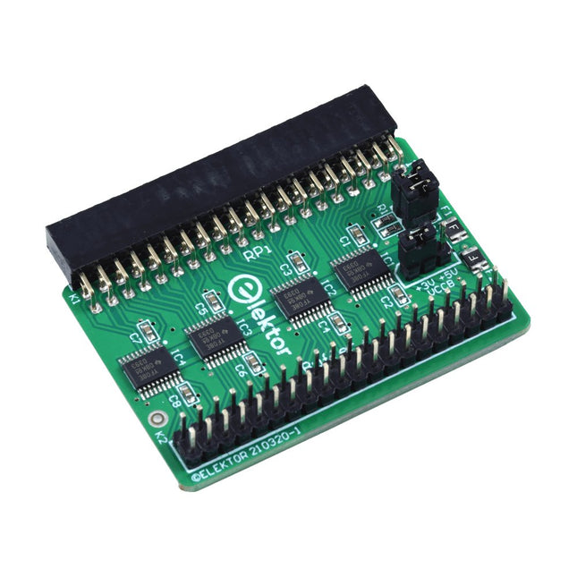
Elektor Labs Elektor Raspberry Pi Buffer Board
Wanneer u regelmatig experimenteert met de Raspberry Pi en verschillende externe hardware aansluit op de GPIO-poort via de header, heeft u mogelijk in het verleden schade veroorzaakt. Het Elektor Raspberry Pi Buffer Board is er om dit te voorkomen! Het board is compatibel met de Raspberry Pi Zero, Zero 2 (W), 3, 4, 5, 400 en 500. Alle 26 GPIO's zijn gebufferd met bidirectionele spanningsomzetters om de Raspberry Pi te beschermen tijdens het experimenteren met nieuwe circuits. De printplaat is bedoeld om aan de achterkant van de Raspberry Pi 400/500 te worden geplaatst. De connector voor aansluiting op de Raspberry Pi is een haakse 40-polige connector (2x20). De printplaat is slechts iets breder. Een 40-polige flatcable met bijpassende 2x20 headers kan worden aangesloten op de buffer-uitgangsheader om bijvoorbeeld te experimenteren met een circuit op een breadboard of een printplaat. Het circuit maakt gebruik van 4x TXS0108E IC's van Texas Instruments. De printplaat kan ook rechtop op een Raspberry Pi worden geplaatst. Downloads Schematics Layout
€ 34,95€ 29,95
Beste prijs
-

Elektor Bundles Elektor Raspberry Pi Pico Advanced Kit (Bundel)
Uitgebreide boek-hardwarebundel voor de RP2040-microcontroller met meer dan 80 projecten Ontgrendel het potentieel van moderne controllertechnologie met de Raspberry Pi Pico in deze bundel. Perfect voor zowel beginners als ervaren gebruikers, biedt de eenvoudig te volgen handleiding u de mogelijkheid om te starten bij de basis van elektronica en verder te gaan naar de complexiteit van digitale signaalverwerking. Met de Raspberry Pi Pico, de speciaal ontworpen hardwarekit en het programmeren in MicroPython, leert u de belangrijkste principes van schakelingen ontwerpen, gegevens verzamelen en verwerken. Ga aan de slag met meer dan 80 projecten, zoals een stopwatch met OLED-display, een laserafstandsmeter en een servogestuurde ventilator. Deze projecten zijn bedoeld om u te helpen het geleerde toe te passen in praktijkscenario's. Het boek behandelt ook geavanceerde onderwerpen zoals draadloze RFID-technologie, objectdetectie en sensorintegratie voor robotica. Of u nu uw vaardigheden op het gebied van elektronica wilt uitbreiden of dieper in ingebedde systemen wilt duiken, deze bundel is de perfecte hulpbron om u te helpen het volledige potentieel van de Raspberry Pi Pico te verkennen. Inhoud van de bundel 1x Projectboek (273 pagina's) 1x Raspberry Pi Pico H 1x Smart Car Kit Elektronische onderdelen 2x Soldeerloze broodplank (400 gaten) 1x Soldeerloze broodplank (170 gaten) 5x Kleurrijke 5 mm LED's (groen, rood, blauw, geel en wit) 1x Laserzender 1x Passieve zoemer 1x Micro-USB-kabel (30 cm) 1x 65 doorverbindingsdraden 1x 20 cm mannelijk naar vrouwelijk Dupont-draad 1x Doorzichtig hoesje 1x Magneet (Diameter: 8 mm, Dikte: 5 mm) 1x Draaipotentiometer 10x 2 KΩ-weerstanden 2x M2,5x30 mm koperen pilaren 10x Kruiskopschroeven met kruiskop 10x M2.5 nikkel-zeskantmoeren 1x 2-inch dual-purpose schroevendraaier Modulen 1x RGB-module 1x 9G-servo 1x XY-joystickmodule met dubbele as 1x RC522 RFID-module 1x 4 bits digitale LED-displaymodule 1x Verkeerslichtdisplaymodule 1x Rotary Encoder-module 1x 1602 LCD-displaymodule (blauw) 1x Fotoweerstandsmodule 1x DC-motor met mannelijke Dupont-draad 1x Ventilatorblad 1x Regendruppelsmodule 1x OLED-module 1x Membraanschakelaartoetsenbord 1x Mini magnetische veermodule 1x Infraroodafstandsbediening 1x Infraroodontvangermodule 1x DC stappenmotor driverbord 1x Button Sensoren 1x Trillingssensor 1x Bodemvochtsensor 1x Geluidssensor 1x Mini PIR-bewegingssensor 1x Temperatuur- en vochtigheidssensor 1x Vlamsensor 2x Crashsensor 2x Volgsensor 1x Ultrasone sensor
€ 99,95€ 79,95
Beste prijs
-
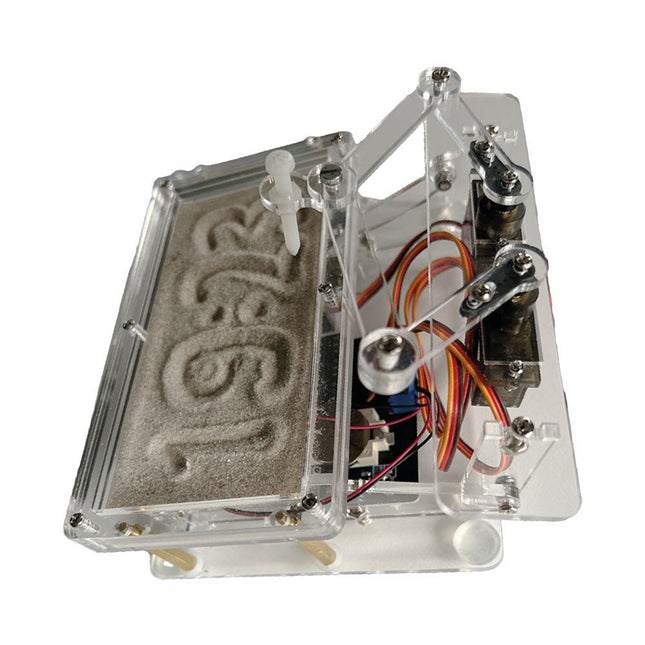
Elektor Labs Elektor Zandklok voor Raspberry Pi Pico
Een op de Raspberry Pi Pico gebaseerde Eye Catcher Een standaard zandklok laat meestal slechts zien hoe de tijd verstrijkt. Deze door een Raspberry Pi Pico aangestuurde zandklok toont daarentegen de exacte tijd door de vier cijfers voor uren en minuten in een zandlaag te "graveren". Na een vooraf ingestelde periode wordt het zand door twee trilmotoren vlak getrild en begint alles weer van voren af aan. Het hart van de zandklok wordt gevormd door twee servomotoren, die via een pantograafmechanisme een schrijfpen aandrijven. Een derde servomotor tilt deze pen op en neer. Het zandbakje is voorzien van twee trilmotoren om het zand weer vlak te trillen. Het elektronische deel van de zandklok bestaat uit een Raspberry Pi Pico en een RTC/driverbord met een real-time klok, plus drivercircuits voor de servomotoren. Een gedetailleerde bouwhandleiding is beschikbaar via download. Kenmerken Afmetingen: 135 x 110 x 80 mm Bouwtijd: ca. 1,5 tot 2 uur Inbegrepen 3x Voorgesneden acrylaatplaten met alle mechanische onderdelen 3x Mini servomotoren 2x Trilmotoren 1x Raspberry Pi Pico 1x RTC/driverkaart met geassembleerde onderdelen Moeren, boutjes, afstandhouders en draden voor de montage Fijnkorrelig wit zand
€ 49,95€ 39,95
Beste prijs
-

Elektor Labs Elektor Zandklok voor Raspberry Pi Pico (incl. Laserkop Upgrade)
Dit bundel bevat de populaire Elektor zandklok voor Raspberry Pi Pico en de nieuwe Elektor laserkop upgrade, en biedt daarmee nog meer mogelijkheden om de tijd weer te geven. U kunt de actuele tijd nu niet alleen in zand "graveren", maar ook op een lichtgevende folie schrijven of groene tekeningen maken. Inhoud van de bundel Elektor Zandklok voor Raspberry Pi Pico (normale prijs: € 50) Elektor Laserkop Upgrade voor Zandklok (normale prijs: € 35) Zandklok voor Raspberry Pi (een op de Raspberry Pi Pico gebaseerde Eye Catcher) Een standaard zandklok laat meestal slechts zien hoe de tijd verstrijkt. Deze door een Raspberry Pi Pico aangestuurde zandklok toont daarentegen de exacte tijd door de vier cijfers voor uren en minuten in een zandlaag te "graveren". Na een vooraf ingestelde periode wordt het zand door twee trilmotoren vlak getrild en begint alles weer van voren af aan. Het hart van de zandklok wordt gevormd door twee servomotoren, die via een pantograafmechanisme een schrijfpen aandrijven. Een derde servomotor tilt deze pen op en neer. Het zandbakje is voorzien van twee trilmotoren om het zand weer vlak te trillen. Het elektronische deel van de zandklok bestaat uit een Raspberry Pi Pico en een RTC/driverbord met een real-time klok, plus drivercircuits voor de servomotoren. Een gedetailleerde bouwhandleiding is beschikbaar via download. Kenmerken Afmetingen: 135 x 110 x 80 mm Bouwtijd: ca. 1,5 tot 2 uur Inbegrepen 3x Voorgesneden acrylaatplaten met alle mechanische onderdelen 3x Mini servomotoren 2x Trilmotoren 1x Raspberry Pi Pico 1x RTC/driverkaart met geassembleerde onderdelen Moeren, boutjes, afstandhouders en draden voor de montage Fijnkorrelig wit zand Elektor Laserkop Upgrade voor Zandklok De nieuwe Elektor Laserkop transformeert de Elektor Zandklok in een klok die de tijd op glow-in-the-dark-film schrijft in plaats van op zand. Naast het weergeven van de tijd kan het ook worden gebruikt om kortstondige tekeningen te maken. De 5 mW laserpointer, met een golflengte van 405 nm, produceert heldergroene tekeningen op de glow-in-the-dark-film. Voor het beste resultaat gebruikt u de kit in een slecht verlichte kamer. Waarschuwing: Kijk nooit rechtstreeks in de laserstraal! De kit bevat alle benodigde componenten, maar het solderen van drie draden is vereist. Opmerking: Deze kit is ook compatibel met de originele Arduino-gebaseerde Zandklok uit 2017. Voor meer details, zie Elektor 1-2/2017 en Elektor 1-2/2018.
€ 84,95€ 69,95
Beste prijs
-
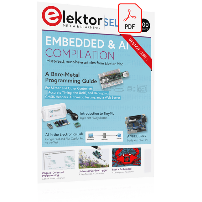
Elektor Digital Elektor Select: Embedded & AI (PDF)
This collection features the best of Elektor Magazine's articles on embedded systems and artificial intelligence. From hands-on programming guides to innovative AI experiments, these pieces offer valuable insights and practical knowledge for engineers, developers, and enthusiasts exploring the evolving intersection of hardware design, software innovation, and intelligent technology. Contents Programming PICs from the Ground UpAssembler routine to output a sine wave Object-Oriented ProgrammingA Short Primer Using C++ Programming an FPGA Tracking Down Microcontroller Buffer Overflows with 0xDEADBEEF Too Quick to Code and Too Slow to Test? Understanding the Neurons in Neural NetworksEmbedded Neurons MAUI Programming for PC, Tablet, and SmartphoneThe New Framework in Theory and Practice USB Killer DetectorBetter Safe Than Sorry Understanding the Neurons in Neural NetworksArtificial Neurons A Bare-Metal Programming Guide Part 1: For STM32 and Other Controllers Part 2: Accurate Timing, the UART, and Debugging Part 3: CMSIS Headers, Automatic Testing, and a Web Server Introduction to TinyMLBig Is Not Always Better Microprocessors for Embedded SystemsPeculiar Parts, the Series FPGAs for BeginnersThe Path From MCU to FPGA Programming AI in Electronics DevelopmentAn Update After Only One Year AI in the Electronics LabGoogle Bard and Flux Copilot Put to the Test ESP32 and ChatGPTOn the Way to a Self-Programming System… Audio DSP FX Processor Board Part 1: Features and Design Part 2: Creating Applications Rust + EmbeddedA Development Power Duo A Smart Object CounterImage Recognition Made Easy with Edge Impulse Universal Garden LoggerA Step Towards AI Gardening A VHDL ClockMade with ChatGPT TensorFlow Lite on Small MicrocontrollersA (Very) Beginner’s Point of View Mosquito DetectionUsing Open Datasets and Arduino Nicla Vision Artificial Intelligence Timeline Intro to AI AlgorithmsPrompt: Which Algorithms Implement Each AI Tool? Bringing AI to the Edgewith ESP32-P4 The Growing Role of Edge AIA Trend Shaping the Future
€ 9,95
Leden: € 8,96
-

Elektor Digital Elektor September/Oktober 2020 (PDF)
USB-S/PDIF-INTERFACEdigitale audio-uitgang voor computer, laptop, tablet of smartphone MULTITASKING MET DE ESP32 (4)binaire semaforen TIMER VOOR HOOFDTELEFOONVERSTERKER DRAADLOZE TEMPERATUURSENSOR VOOR NIXIE BARGRAPH THERMOMETERmultifunctionele oplossing met ontwerptruc MULTITASKING MET DE RASPBERRY PIvoorbeeld: controller voor verkeerslichten OPEN-NETWERK WEERSTATION MK2deel 2: software DOMOTICA HELEMAAL NIET MOEILIJKmet ESPHome, Home Assistant & MySensors DE GEHEUGEN-BEELDBUISvreemde onderdelen AI VOOR BEGINNERS (3)een eigen neuraal netwerk PIC’S PROGRAMMEREN: VAN DE GROND AFeen sinus in assembler IKEA-HACKeen goedkope IKEA-lamp ‘tunen’ met NeoPixel-LED’s en WLAN LAAT JE HOBBYPROJECT NIET IN EEN HOEKJE VERSTOFFENaanbodzijde-tijdmanagement en spiraalontwikkeling ALLE BEGIN......hoeft niet zo moeilijk te zijn OOST WEST LAB BESTeen blik in het allerheiligste, waar interessante projecten worden geboren DE 8-BIT MICROCONTROLLER – EN DAARNAvraaggesprek met Tam Hanna WIE HET KLEINE NIET EERTuit de ideeënbus van Elektor REVIEW: OWON OW18E BLUETOOTH-MULTIMETER INTERACTIEFcorrecties & updates || vragen & antwoorden UIT HET LEVEN GEGREPENloodvrij solderen en Europese regelneverij VEELBELOVEND PROJECT: NIEUWE LCR-METER 50 HZ...2 MHZprecisie en gebruiksgemak ERROR ANALYSIStips en trucs: FMEA, grote stromen en meer DEVELOPER’S ZONEtips & trucs, vakkunstigheden en andere nuttige informatie REVIEW: SIGLENT SDL1020X-E ELEKTRONISCHE BELASTING HOOGSPANNINGSVOEDING MET KARAKTERISTIEKENSCHRIJVERspanningen tot 400 V instellen en karakteristieken van buizen en transistoren meten HEXADOKU SEPTEMBER/OKTOBER 2020 ANALOGE ELEKTRONICA ONTWERPENcase-study #2 – deel 1: theorie van analoge filters SCHEMA’S TEKENEN
€ 9,95
-

Elektor Digital Elektor September/Oktober 2021 (PDF)
KENNISMAKING MET NEURONEN IN NEURALE NETWERKEN (DEEL 1)Kunstmatige Neuronen EMC PRE-COMPLIANCE TEST VOOR UW DC-GEVOED PROJECT (DEEL 1)Dubbele DC-LISN ELEKTRONISCHE BELASTING VOOR DC EN ACTot 400 V en 10 A (piek) ALLE BEGIN......neemt het op tegen de spoel! BEELDVERWERKING MET DE NVIDIA JETSON NANO (DEEL 1)De Hardware en Software EEN GEDETAILLEERD ONDERZOEK NAAR NETTRANSFORMATORENIn- en uitschakelgedrag YES WE CAN MET PICAN 3Een CAN Bus HAT voor de Raspberry Pi 4 ZONNEPANELEN OP JE BALKONZelfbouw balkoncentrale = snel terugverdiend! BEELDVERWERKING EN VIDEO-STREAMING MET EEN RASPBERRY PI 4De Raspberry Pi High-Quality Camera in de praktijk DISPLAYS GEBRUIKEN IN RASPBERRY PI-PROJECTENEen hoofdstuk als voorbeeld: Organische LED-displays (OLED) KENNISMAKING MET DE PARALLAX PROPELLER 2 (DEEL 4):Tekens Versturen ELEKTOR @ 60Een terugblik op voorgaande septembers OOST WEST LAB BESTop het Friese platteland, waar de buizen bloeien... HYBRIDENVreemde onderdelen, de serie EEN KOMPASROOS MET DE GY-271Of waarom we in een acht bewegen om een sensor te kalibreren HOE GROOT IS UW VOETAFDRUK?Bereken de ecologische voetafdruk van uw elektronica CONNECTED THERMOSTAAT MET ESP32Houd uw wijn op de juiste temperatuur! MAGNETISCHE LEVITATIE OP DE DIGITALE MANIERESP32 Pico vervangt de Analoge Comparator ULTIMATE ARDUINO UNO HARDWARE MANUALEen hoofdstuk als voorbeeld: Main Microcontroller Bootloader MICROPYTHON VOOR DE ESP32 C.S. (DEEL 2)Eenvoudig Matrix Displays besturen MADMACHINE SWIFTIO BOARDModerne taal ontmoet moderne Hardware UIT HET LEVEN GEGREPENKnipperlichtrelatie HEXADOKUThe Original Elektorized Sudoku
€ 9,95
-

Elektor Digital Elektor September/Oktober 2022 (PDF)
electronica fast forward Start- & Scale-Up Awards les préparatifs vont de plus en plus vite ! Bluetooth Low Energy avec ESP32-C3 et ESP32 il n'est pas toujours nécessaire que ce soit le WiFi ! Renifleur Bluetooth LE pirater un dongle USB Makerdiary nRF52840 MDK Cube LED RVB magique concevoir du matériel autour d'un RP2040 Marche/arrêt automatique pour le compresseur de pâte à souder Productions vidéo Elektor livestreams, webinaires et cours pour ingénieurs et pro-makers Électrifiez votre vélo avec un kit de conversion vélo électrique Tous les débuts... ...multiplie les tensions Tiré de la vie activités annexes Teensy 4.0 – pourquoi cette planche est-elle si rapide ? la vitesse n'est pas de la sorcellerie ! Simulation d'un amplificateur de puissance audio avec TINA essayez d'abord, puis construisez Développez et gérez vos propres nœuds LoRaWAN IoT exemple de chapitre : modules Dragino LHT65, LDS01 et LDS02 LoRaWAN Projet 2.0 corrections, mises à jour et lettres des lecteurs 5G – juste pour moi contrôle total sur les déploiements 5G avec son propre réseau cellulaire Infographie Elektor Conseils pour développer une interface WiFi équiper les applications avec des interfaces WiFi Horloge de tour du Rhin Mk 2 Analyseur de spectre audio avec dékatrons nouvelle vie pour les tubes vintage Envoyer des données à Telegram avec un ESP32 et quelques pièces Un filtre coupe-bande Fliege pour les mesures audio mesure mieux avec un filtre coupe-bande Changer les communications industrielles Ethernet à paire unique – bien plus qu'un simple nouveau connecteur PUT-ter mâle électronique voici comment fonctionne le transistor unijonction programmable Écran tactile rond pour Raspberry Pi HyperPixel 2.1 rond de Pimoroni Télédétection avec détection de perte de connexion avec modules nRF24L01+ Récepteur FM numérique avec Arduino et TEA5767 régler avec un Arduino Nano Convertir l'interface OLED de SPI en I²C Meilleur laboratoire Est-Ouest un passe-temps ne prend pas sa retraite... Dix ans d'éthique en électronique Tessel Renzenbrink à propos de la société numérique et bien plus encore Hexadoku Le Sudok électorisé original
€ 9,95
-

Elektor Digital Elektor September/Oktober 2023 (PDF)
Elektor GREEN en GOLD leden kunnen deze uitgave hier downloaden.Nog geen lid? Klik hier om een lidmaatschap af te sluiten. Raspberry Pi Pico als spectrumanalyzerFFT’s met goedkope hardware ±40 V lineaire spanningsregelaaralternatieve voeding voor de Fortissimo-100 eindversterker... en andere! Flexibele draadloze communicatie met een MCUEEPROM opent netwerkmogelijkheden voor draadloze MCU’s € 5000 voor het oprapen!doe mee aan de STM32 Wireless Innovation Design Contest 2023: een AI-odysseeaan de slag met Code Interpreter van ChatGPT LoRa – een Zwitsers zakmesdeel 1: het LoRa-protocol en zijn voordelen Instelbare current sink met geïntegreerde klokgeneratortest voedingen, spanningsconverters en accu’s Twee nieuwe Arduino UNO R4-boards: Minima en WiFi Logaritmische potentiometersze zijn exponentieel! Motordriver breakout-boardeen BoB voor een 5 A DC-motordriver van 3×3 mm Uit het leven gegrepenelektronica periculosa Biedt cellulair het laagste stroomverbruik voor IoT?energie-eisen van LTE-M en NB-IoT in LPWAN-implementaties Draadloze communicatie in IoT-systemen met Arduino MKR-moduleshet juiste board voor WiFi, LoRa en andere standaarden AC-verliezen in magnetische componentenvoorkom hete spoelen! Meten voor optimale cloud-connectiviteit Matter implementatie: Wat is er nodig om Matter-devices in te zetten? YARD Stick Onesub-1 GHz draadloos testtool Houdrelaisvreemde onderdelen PIC voor tien – precies op tijdontwerp van een SDR-tijdseinontvanger Due Diligence DirectiveBusiness as Usual Will Not Do Alle begin......versterkt spanningen Infrageluid-recorder met de Arduino Pro Minieen voorbeeldproject uit de Elektor-uitgave “Arduino & Co” Cloud-gebaseerde energiemetermet een ESP32-module en een PZEM-004T spanning/stroom-sensor Een gids voor puristisch programmeren (deel 2)nauwkeurige timing, de UART en debugging
€ 9,95
-

Elektor Digital Elektor September/Oktober 2024 (PDF)
Elektor GREEN en GOLD leden kunnen deze uitgave hier downloaden. Nog geen lid? Klik hier om een lidmaatschap af te sluiten. Autonome sensor-nodeLoRa-gebaseerde datatransmissie, voeding met zonnecellen Elektor eXpansion Board v1.0voor ESP32S3 en andere XIAO-controllerboards Modeltrein met camerainbouw van een ESP32 CAM-module Breedbandige magnetische lange golf-antenneontvang meerdere kanalen zonder afstemmen TensorFlow Lite op kleine microcontrollersvanuit het standpunt van een (absolute) beginner Een hub voor RS-422- en RS-485-apparatende bus is de ster! RF-sondemet LED-staafdiagram Alle begin......bekijkt meer opampschakelingen Open VarioEen Open-Source Multifunctie Variometer voor Paragliden Uit het leven gegrepenover de vanzelfsprekendheid der dingen AI-gebaseerde watermeter-uitlezing (2)koppel uw oude watermeter met het IoT! Slimme landbouwdetectie van ongedierte op basis van machine learning met IoT-connectiviteit Waarom Anybus CompactCom de ideale keuze is voor embedded industriële communicatie Communicatie standaard IQRFBetrouwbaarheid voor draadloze, low-rate Mesh-netwerken met verlies Constructie van een slimme landbouwrobotbelangrijkste technische overwegingen en uitdagingen Audio-notchfilter met instelbare frequentieuniversele oplossing voor het onderdrukken van frequenties in audiotoepassingen Het LeoINAGPS-systeemnuttige informatie over uw elektrische voertuig LoRa-node op zonne-energieeenmodulaire, compacte en veelzijdige IoT-oplossing AWS voor Arduino en co. (2)data versturen met AWS IoT ExpressLink Project 2.0correcties, updates en brieven van lezers 2024: een AI-odysseedesktop- versus embedded accelerators: enkele opties ESP32-bereiksuitbreidingeen eenvoudige antenne-modificatie WoTS 2024World of Industry, Technology & Science biedt oplossingen Metafas @ WoTS 2024Smart thinking in printed electronics Hansamatrix @ WoTS 2024 Value Procurement Centre @ WoTS 2024Omdat niet alles in Nederland kan! PCBWay @ WoTS 2024 GW Instek @ WoTS 2024 Rohde & Schwarz @ WoTS 2024 Unis Group @ WoTS 2024 Eurocircuits @ WoTS 2024Jouw Pad naar Uitmuntendheid in Elektronica Productie
€ 9,95
-
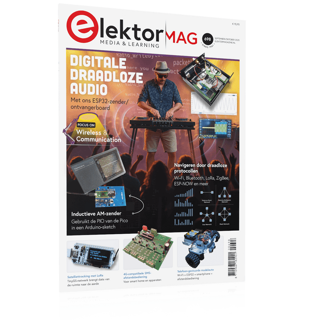
Elektor September/Oktober 2025 (NL)
Elektor GREEN en GOLD leden kunnen deze uitgave hier downloaden. Nog geen lid? Klik hier om een lidmaatschap af te sluiten. ESP32 Audio Transceiver Board (Deel 2)Draadloze audio-overdracht Inductieve AM-zenderGebruikt Pico's PIO in een Arduino-sketch Navigeren door draadloze protocollen navigerenEen technische gids Satelliettracking met behulp van LoRaHet TinyGS-netwerk brengt gegevens uit de ruimte naar de aarde. 4G-Compatibele SMS afstandsbedieningBedien je apparatuur op afstand Hogesnelheids-probeIngangen met hoge impedantie voor signalen tot 200 MHz Uit het leven gegrepenKafka KrakenSDR Prestatietests met de RP2350Is een upgrade van Raspberry Pi Pico 1 naar versie 2 de moeite waard? Contactloze E-veldmetingen (2)Een laservibrometer voor het beoordelen van de trillingen van het membraan Kristallen en oscillatorenVerbetering van de kristalnauwkeurigheid door gerichte keuze van condensatoren Alle begin......gaat audio! Zelf firmware coderen voor embedded projecten SPECTRAN® V6 MobileModulaire, configureerbare realtime-spectrumanalyzer voor betrouwbare metingen over alle frequentiebereiken De toekomst van AI wordt gesmeed in siliciumEen interview met Anastasiia Nosova Autonome Sensor-Node v2.0 (Systeemarchitectuur)Zonne-energieplatform met geïntegreerde GPS, LoRaWAN en meer Precieze positioneringBluetooth channel sounding getest Testgestuurd ontwikkelen bij het schrijven van firmware Telefoon gestuurde modelautoWi-Fi + ESP32 + Smartphone = Afstandsbediening 2025: Een AI-odysseeAI-redeneermodellen: De gedachtegang-revolutie Zonne-laadregelaar met MPP-tracking (3)Software en Inbedrijfstelling Raspberry Pi Zero Web Streaming CameraDe ZeroTier VPN gebruiken Beste soldeerder van de Beneluxvakmanschap in de schijnwerpers Seminaroverzicht Electronics & ApplicationsLeer, ontdek en netwerk op E&A 2025 Eurocircuits at E&A 2025 E&A gadget 2025: racen over de beursvloer met slimme printplaat op wielenVijf vragen aan Casper van Doorne, ontwerper van de beursgadget Beursgadget E&A bekendontwerp en bestuur je eigen raceauto Vakbeurs E&A is het elektronicaparadijs van de Benelux“Techneuten blijven kinderen” Rohde & SchwarzPioneering Innovation in Test & Measurement Diederik Jekel opent Electronics & Applications
€ 15,95
-

Elektor Digital Elektor September/Oktober 2025 (PDF) NL
Elektor GREEN en GOLD leden kunnen deze uitgave hier downloaden. Nog geen lid? Klik hier om een lidmaatschap af te sluiten. ESP32 Audio Transceiver Board (Deel 2)Draadloze audio-overdracht Inductieve AM-zenderGebruikt Pico's PIO in een Arduino-sketch Navigeren door draadloze protocollen navigerenEen technische gids Satelliettracking met behulp van LoRaHet TinyGS-netwerk brengt gegevens uit de ruimte naar de aarde. 4G-Compatibele SMS afstandsbedieningBedien je apparatuur op afstand Hogesnelheids-probeIngangen met hoge impedantie voor signalen tot 200 MHz Uit het leven gegrepenKafka KrakenSDR Prestatietests met de RP2350Is een upgrade van Raspberry Pi Pico 1 naar versie 2 de moeite waard? Contactloze E-veldmetingen (2)Een laservibrometer voor het beoordelen van de trillingen van het membraan Kristallen en oscillatorenVerbetering van de kristalnauwkeurigheid door gerichte keuze van condensatoren Alle begin......gaat audio! Zelf firmware coderen voor embedded projecten SPECTRAN® V6 MobileModulaire, configureerbare realtime-spectrumanalyzer voor betrouwbare metingen over alle frequentiebereiken De toekomst van AI wordt gesmeed in siliciumEen interview met Anastasiia Nosova Autonome Sensor-Node v2.0 (Systeemarchitectuur)Zonne-energieplatform met geïntegreerde GPS, LoRaWAN en meer Precieze positioneringBluetooth channel sounding getest Testgestuurd ontwikkelen bij het schrijven van firmware Telefoon gestuurde modelautoWi-Fi + ESP32 + Smartphone = Afstandsbediening 2025: Een AI-odysseeAI-redeneermodellen: De gedachtegang-revolutie Zonne-laadregelaar met MPP-tracking (3)Software en Inbedrijfstelling Raspberry Pi Zero Web Streaming CameraDe ZeroTier VPN gebruiken Beste soldeerder van de Beneluxvakmanschap in de schijnwerpers Seminaroverzicht Electronics & ApplicationsLeer, ontdek en netwerk op E&A 2025 Eurocircuits at E&A 2025 E&A gadget 2025: racen over de beursvloer met slimme printplaat op wielenVijf vragen aan Casper van Doorne, ontwerper van de beursgadget Beursgadget E&A bekendontwerp en bestuur je eigen raceauto Vakbeurs E&A is het elektronicaparadijs van de Benelux“Techneuten blijven kinderen” Rohde & SchwarzPioneering Innovation in Test & Measurement Diederik Jekel opent Electronics & Applications
€ 9,95
-

Elektor Digital Elektor Septembre/Octobre 2024 (PDF)
Le téléchargement intégral de ce numéro est disponible pour nos membres GOLD et GREEN sur le site Elektor Magazine ! Pas encore membre ? Cliquez ici. un nœud de capteurs autonometransmission de données basée sur LoRa et alimentation en énergie par cellules solaires la carte eXpansion V1.0 d'Elektorpour ESP32S3 et autres cartes XIAO une caméra dans un train miniatureinstallation d’un module ESP32 CAM antenne magnétique à large bande pour les grandes ondestous les émetteurs sans aucun accord TensorFlow Lite pour microcontrôleurspar un débutant, pour les débutants un concentrateur pour les appareils RS-422 et RS-485câbler votre bus comme une star sonde RFWith LED Bar Graph démarrer en électronique...…plus de montages à ampli-op Open Variovariomètre multifonction open source pour vol en parapente sur le vifÀ propos de prendre les choses pour acquises relevé des compteurs d'eau basé sur l'IA (Partie 2)intégrez votre ancien compteur dans l'IdO ! agriculture intelligentedétection des nuisibles basée sur l’apprentissage machine avec connectivité IdO Anybus CompactCom est le choix idéal pour la communication industrielle embarquée – voici pourquoi norme de communication IQRFfiabilité des réseaux maillés sans fil à faible débit avec perte comment construire un robot agricole intelligentquelles sont les considérations essentielles que les concepteurs de robots agricoles doivent prendre en compte et à quels défis techniques sont-ils confrontés ? filtre coupe-bande audio à fréquence réglablesolution universelle de suppression de fréquences dans le domaine audio le système LeoINAGPSsurveillez votre véhicule électrique nœud LoRa alimenté par énergie solaireune solution IdO modulaire, compacte et polyvalente AWS pour Arduino et cie. (2)transmission de données avec AWS IoT ExpressLink projet 2.0corrections, mises à jour et courrier des lecteurs 2024 : l'odyssée de l'IAexamen des Accélérateurs IA : comparaison extension de couverture Wi-Fi sur ESP32comment modifier simplement une antenne
€ 10,95
-
Elektor Septembre/Octobre 2025 (FR)
Le téléchargement intégral de ce numéro est disponible pour nos membres GOLD et GREEN sur le site Elektor Magazine ! Pas encore membre ? Cliquez ici. carte émetteur-récepteur audio ESP32 (2)Transmission audio sans fil émetteur AM par inductionUtiliser les PIO du Pico dans un croquis Arduino les protocoles sans filUn guide technique suivi de satellites avec LoRaTinyGS, le réseau open source qui capte les données spatiales télécommande par sms compatible 4GContrôlez votre équipement à distance sonde haute vitesseMesure à haute impédance jusqu’à 200 MHz sur le vifKafka KrakenSDR tests de performance avec le RP2350Pico 2 : une vraie amélioration ? mesures de champ électrique sans contact (2)Un vibromètre laser pour l’analyse des vibrations de la membrane quartz et oscillateursAméliorer la précision des quartz grâce au choix des condensateurs démarrer en électroniqueCI audio originaux se lancer dans le codage d'un projet DIY SPECTRAN® V6 MobileAnalyseur de spectre temps réel modulaire et configurable pour des mesures fiables sur l’ensemble des plages de fréquences l’avenir de l’IA repose sur le siliciumEntretien avec Anastasiia Nosova nœud de capteurs autonome v2.0 (architecture du système)Plateforme de mesure autonome alimentée par énergie solaire, avec GPS intégré, LoRaWAN et plus encore positionnement précisTests du sondage de canal Bluetooth développement logiciel piloté par les tests voiture miniature contrôlée par SmartphoneWi-Fi + ESP32 + Smartphone = contrôle à distance 2025 : une odyssée de l’IAModèles de raisonnement en IA : la révolution de la chaîne de pensée contrôleur de charge solaire avec MPPT (3)Logiciel et mise en service caméra Web Raspberry Pi ZeroStreaming avec VPN ZeroTier
€ 15,50


