Producten
-

Elektor Digital 307 Circuits FR (E-book)
307 schémas d'électronique analogique, logique ou numérique, tous signés Elektor. Voici une mine d'idées, de trouvailles et d'astuces. Beaucoup sont présentés sous une forme assez élaborée, avec plan détaillé, dessin du circuit imprimé, liste des compositions complètes et circuit imprimé... ces célèbres dessins sont à la base d'une grande partie de la réputation de l'Électricien. Tous les domaines de prédilection de l'électronique sont abordés : audio, vidéo, auto, moto, vélo, maison, loisirs, HF, mesure, test, alimentation et micro-informatique. Depuis le processus de production de la série, les 307 circuits sont une véritable ligne directrice pour l'électronique moderne, source des idées originales qui guident le processus de travail sur les variantes. Recevez les articles qui intéressent le nombre de doubles publiés dans la revue d'Elektor, publiés par la tradition du présent et publiés, et le nombre d'appels de Hors-Gabarit, conformes aux exceptions en vigueur. Voici les domaines familiaux et les usages de l'électronique : alimentations, régulateurs et chargeurs audio Video communication hautes fréquences informatique jeux & modélisme maison et automobile mesurer et tester processeur et contrôleur
€ 29,95
Leden: € 26,96
-

Elektor Digital 310 Circuits (PDF)
Cet ouvrage est un trésor : il réunit 310 schémas d'électronique analogique, logique ou numérique, des programmes, des liens vers des sites internet, des tableaux de caractéristiques de composants et des dessins de circuit imprimé. Il est le onzième volume de la collection « 300 circuits » (301... 302... 303... 304... 305... 306... 307... 308... 309 circuits). Ses deux tables des matières alphabétique et thématique vous permettent de trouver rapidement et facilement parmi les 310 articles proposés ceux qui correspondent à vos besoins. Ces articles viennent des numéros doubles de la revue Elektor, publiés chaque année en été, et appelés numéros Hors-Gabarit, par allusion à leur contenu exceptionnellement riche. Ils forment un véritable catalogue d'idées, de trouvailles et d'astuces. C'est une source d'inspiration inépuisable, et à partir de laquelle chacun élaborera ses propres variantes qu'il combinera ensuite à sa guise avec d'autres circuits. Tous les domaines familiers et usuels de l'électronique sont abordés : alimentations, régulateurs et chargeurs audio & vidéo communication hautes fréquences informatique jeux & modélisme maison & automobile mesure & test processeur & contrôleur Les robots et leurs accessoires (moteurs, capteurs, mécanique) arrivent en force. Certaines de ces réalisations sont présentées sous une forme succincte, d'autres sont élaborées avec schéma détaillé, dessin de circuit imprimé, liste de composants complète et circuit imprimé, ces fameux circuits imprimés qui ont fait une partie de la réputation d'Elektor. Un concentré de tout le savoir-faire du laboratoire d'Elektor pour un prix modique. On y trouve beaucoup plus que ce qu'on y cherche.
€ 29,95
Leden: € 26,96
-

Elektor Digital 310 Schakelingen (E-book)
310 Schakelingen – alweer het elfde boek uit de bekende „driehonderd“-reeks. De 310 schakelingen, tips en ideeën in dit boek vormen een (bijna) onuitputtelijke schatkamer op alle terreinen die de elektronica rijk is: audio en video, hobby en modelbouw, hoogfrequenttechniek, huis en tuin, meten en testen, microprocessor, PC-hardware en -software, voedingen en acculaders plus al dat andere dat niet zo gemakkelijk in een van deze categorieën kan worden ondergebracht. 310 Schakelingen – bevat veel complete oplossingen of in elk geval de aanzet daartoe. En de 310 beschreven schakelingen vormen in elk geval een bron van inspiratie voor nieuwe eigen ontwikkelingen! 310 Schakelingen – samengesteld uit de Halfgeleidergidsen van 2006, 2007 en 2008. De Halfgeleidergids is het jaarlijkse dubbeldikke juli/augustus-zomernummer van het maandblad Elektor. 310 Schakelingen – een must voor iedereen die creatief met elektronica bezig is, beroepsmatig of als hobby. 310 Schakelingen – met dit jaar een speciaal aan robots en robotica gewijde sectie.
€ 29,95
Leden: € 26,96
-

Elektor Digital 311 circuits (E-book)
Cet ouvrage est un trésor : il réunit 311 schémas d'électronique analogique, logique ou numérique, des programmes, des liens vers des sites internet, des tableaux de caractéristiques de composants et des dessins de circuit imprimé. Il est le onzième volume de la collection « 300 circuits » (301... 311 circuits). Ses deux tables des matières alphabétique et thématique vous permettent de trouver rapidement et facilement parmi les 311 articles proposés ceux qui répondront à vos besoins. Ces articles viennent des numéros doubles récents de la revue Elektor, publiés chaque année en été, et appelés numéros Hors-Gabarit, par allusion à leur contenu exceptionnellement riche. Ils forment un véritable catalogue d'idées, de trouvailles et d'astuces. C'est une source d'inspiration inépuisable, et à partir de laquelle chacun élaborera ses propres variantes qu'il combinera ensuite à sa guise avec d'autres circuits. Tous les domaines familiers et usuels de l'électronique sont abordés : alimentations, régulateurs et chargeurs audio & vidéo communication hautes fréquences informatique jeux & modélisme maison & automobile mesure & test processeur & contrôleur robots et leurs accessoires Certaines de ces réalisations sont présentées sous une forme succincte, d'autres sont élaborées avec schéma détaillé, dessin de circuit imprimé, liste de composants complète et circuit imprimé, ces fameux circuits imprimés qui ont fait une partie de la réputation d'Elektor. Un concentré de tout le savoir-faire du laboratoire d'Elektor pour un prix modique. On y trouve beaucoup plus que ce qu'on y cherche.
€ 29,95
Leden: € 26,96
-

Elektor Digital 311 Schakelingen (E-book)
311 Schakelingen is het twaalfde boek uit de gerenommeerde 300-reeks van Elektor. Dat betekent ook dit keer weer een onuitputtelijke bron van inspiratie voor elke elektronicus, hobbyist of professional, en een boek dat in geen enkele boekenkast mag ontbreken! 311 Schakelingen bevat een ruime collectie schakelingen, ideeën, tips en trucs op alle denkbare terreinen van de elektronica: audio en video, hobby en modelbouw, hoogfrequenttechniek, huis en tuin, meten en testen, microprocessor, PC-hard- en software, voedingen en acculaders, en natuurlijk een rubriek 'diversen' voor alles wat niet in een van de andere rubrieken past. Het boek biedt complete oplossingen voor talloze problemen, of de aanzet voor eigen ontwikkelingen. 311 Schakelingen is samengesteld uit de Halfgeleidergidsen van 2009, 2010 en 2011. De Halfgeleidergids is het jaarlijkse dubbeldikke juli/augustusnummer van het maandblad Elektor. Het boek is dus voor een groot deel gebaseerd op inzendingen van lezers van Elektor, aangevuld met bijdragen uit het Elektor-lab.
€ 29,95
Leden: € 26,96
-
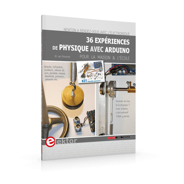
Elektor Digital 36 Expériences de Physique avec Arduino (E-BOOK)
Newton a rendez-vous avec l’électronique 36 Expériences de Physique avec Arduino (E-Book) Pour la maison & l’école Points forts Un peu d'électronique et beaucoup d'experimentation : un livre ludique ! Gravité, réfraction, couleurs, vitesse du son, pendule, masse, élasticité, pression, aimants : une approche nouvelle et créative des leçons de physique Matériel peu coûteux et facilement disponible Logiciels gratuits Kit disponible séparément La rencontre de la physique et du microcontrôleur ne devrait plus étonner personne. Il existe d’excellents enregistreurs de données, ainsi que de nombreux programmes pour les traiter et les présenter sous forme de graphiques colorés et attrayants. La physique rébarbative, c’est fini ! J’ai choisi l’Arduino, car cette plate-forme est d’un accès facile et sa documentation abondante. La famille Arduino offre des ressources extraordinaires à un prix dérisoire. Ajoutez-y le logiciel gratuit CoolTerm, et vous pouvez enregistrer toutes les données de mesure pour les retravailler sous Excel et créer aisément des tableaux ou des graphiques. Ce livre n’est pas un manuel de physique. Vous n’y trouverez ni équations différentielles ni courbes abstraites. Nous étudierons des phénomènes physiques de la vie de tous les jours. Sans chercher à être exhaustif, mon modeste ouvrage apporte aux leçons de physique une approche nouvelle et créative grâce aux techniques modernes de mesure et de traitement des données. L’électronique utilisée est simple, et constitue une belle démonstration des possibilités. Kit de démarrage du livre « 36 expériences de physique avec Arduino » disponible séparément ! - http://www.youtube.com/watch?v=bG_IpyGBKNY- http://www.youtube.com/watch?v=ySBvh8XgyvA L'auteurL’auteur pratique l’électronique depuis de nombreuses années. Ses premiers articles publiés par le magazine Elektor dans ses premiers numéros datent de bien avant l’apparition des petits ordinateurs domestiques pour lesquels il se passionnera. Ses sujets de prédilection devinrent le ZX81 et le standard MSX. Aujourd’hui, il revient avec des idées très personnelles et des projets originaux, pour le plus grand bénéfice des lecteurs intéressés par l’électronique programmée.Revisiter les lois de la physique ? Avec Arduino, c’est instructif et amusant. Il fallait y penser… Gravité, réfraction, couleurs, vitesse du son, pendule, masse, élasticité, pression, aimants… deviennent de passionnants objets d’expérimentation avec Willem van Dreumel.
€ 19,95
Leden: € 17,96
-

Elektor Digital 37 Natuurkunde Projecten met Arduino (E-book)
Voor thuis en op school Dit boekje is gericht op leerlingen en natuurkunde docenten in het voortgezet onderwijs. Met voorbeelden op verschillende gebieden van de fysica, geeft het aan hoe een populair microprocessor platform als Arduino toegepast kan worden in het natuurkunde practicum. We passen Arduino onder andere toe als nauwkeurig meetinstrument, zodat metingen uitgewerkt kunnen worden in een spread sheet. Hoewel enige handigheid niet overbodig is, kunnen de beschreven experimenten kunnen ook uitstekend thuis worden uitgevoerd. In dat opzicht wil dit boek met name bij de jeugd de interesse wekken voor de toepassing van microprocessoren. In de hobbysfeer is dat niet alleen een zinvolle tijdsbesteding, maar bovenal interessant en leuk. Veiligheid staat uiteraard voorop bij het doen van experimenten. Energie, licht en warmte zijn onuitputtelijke bronnen, maar ze kunnen ook gevaar opleveren. Voor dit boek geldt dan ook het motto: Eerst denken, dan doen.
€ 19,95
Leden: € 17,96
-

Elektor Digital 3D Modeling and Printing for Electronics (E-book)
Learn to 3D Model & 3D Print with Tinkercad With this book and the complementary videos, you’ll be 3D printing in no time at all. This course is meant to have you make casings for electronic components but also goes into optimizing your print technique as well as adding a little flair to your 3D creations. The course is perfect for you if you just bought your (first) 3D printer and want to print your own designs as soon as possible while also being able to get more background information. You’ll get to know the workings of a 3D printer and what software to use to model your object, not forgetting to make it print perfectly. We’ll even use the magic of 3D printing to create things that appear impossible to make (this fast and simple) with any other rapid-prototyping technique. At the end of this course, it’ll be second nature for you to design an object for 3D printing and fine-tune your print-setting to get the perfect print! The book includes the following 7 video tutorials: Introduction Basic 3D modeling for 3D printing Modeling a casing Post-processing Pushing the limits Movable parts Snap fits
€ 32,95
Leden: € 29,66
-

Elektor Digital 50 Mini Microcontroller projecten (E-BOOK)
Let op: 2e druk en nieuwe cover! Wie enigszins bekend is met moderne microprocessor systemen als Arduino, kent ongetwijfeld ook de problemen met dit soort kaarten. Ze zijn te duur om voor elk project een aparte kaart aan te schaffen en zijn bovendien nogal fors van formaat. Het aardige van de ATtiny is dat de schijn bedriegt. Het lijkt een klein IC met een beperkt toepassingsgebied, maar het heeft een verbazingwekkend scala aan (speelse) mogelijkheden. Dit boek beschrijft de enorme veelzijdigheid van de ATtiny microcontroller aan de hand van ongeveer vijftig leuke elektronica projecten, speciaal gericht op de beginner. De meeste ontwerpen zijn volledig uitgewerkt, enkele zijn meer als ontwerpidee gepresenteerd. De inhoudsopgave laat zien dat we ons op vele terreinen zullen begeven, van zonnevolger tot helling indicator. Dit boek is beslist geen theorieboek. Het is een boek dat gelezen zal worden met de soldeerbout in de hand. Voor het programmeren van de ATtiny maken we dankbaar gebruik van een Arduino kaart. Als de Arduino ingesteld word als programmer, kunnen we er de meeste Arduino “sketches” mee overzetten naar de ATtiny. We wensen u veel plezier met het nabouwen van de schakelingen.
€ 19,95
Leden: € 17,96
-

Elektor Digital 50 PIC Microcontroller projecten (E-BOOK)
Dit boek bevat 50 leuke en spannende projecten met PIC microcontrollers zoals een laser alarm, USB plaagmuis, eierwekker, jongerenverjager, geluidsschakelaar, capacitieve vloeistofniveau meting, 'vinger in het water' sensor, bewaking van een ruimte met een camera, 220 volt lichtdimmer, pratende microcontroller en nog veel meer. Er komen talloze technieken aan de orde zoals relais, wisselstroomregeling (ook 220 volt), I2C, SPI, RS232, USB, puls breedte modulatie, rotary encoder, interrupts, infrarood, analoog-digitaal conversie (en andersom), 7-segment display en zelfs CAN bus. U kunt dit boek gebruiken om de verschillende projecten na te bouwen en daarna in de praktijk te brengen. Door de duidelijke uitleg, schema's en zelfs foto's van de opstelling is het nabouwen een leuke bezigheid. Bij ieder project wordt uitgelegd waarom het juist op die manier is uitgevoerd, en wordt kort de theorie behandeld. U kunt dit boek dus gebruiken als studieboek, of als basis voor grotere en ingewikkeldere projecten. Alle schakelingen zijn op een steekbord uitgevoerd zodat uitbreiden en aanpassen gemakkelijk is. De drie PIC microcontrollers die in dit boek gebruikt worden, zijn de 16f877A, 18f4455 en 18f4685. Daarnaast komt aan de orde hoe u de programma's van de ene naar de andere microcontroller kunt overzetten (er worden 15 types ondersteund) inclusief twee praktijkvoorbeelden. Alle benodigde software kunt u gratis downloaden. Dat geldt ook voor de open source programmeertaal JAL. Deze krachtige maar toch eenvoudig te leren taal wordt zowel door hobbyisten als professionals gebruikt. Dit boek is ook goed te gebruiken als naslagwerk. U kunt er de uitleg van alle opdrachten van de programmeertaal JAL in terugvinden, en tevens van de gebruikte uitbreidingsbibliotheken. Via de index vindt u gemakkelijk projecten die als voorbeeld kunnen dienen voor de belangrijkste JAL opdrachten. Zelfs wanneer u alle projecten een keer gemaakt hebt, zal dit boek nog lang een plekje naast uw PC behouden. Voor meer informatie en downloadlinks ga naar de bijbehorende supportpagina ATTACHMENTS / DOWNLOADS Inhoudsopgave 50 mini-microcontroller projecten (Grootte: 1.12 MB) Software-50 PIC Microcontroller projects (Grootte: 11.72 MB)
€ 29,95
Leden: € 26,96
-

Elektor Bundles 555 Timer Projecten (Bundel)
Deze bundel gaat helemaal over het ontwerpen van projecten gebaseerd op de 555 timer IC. Het boek bevat meer dan 45 volledig geteste en gedocumenteerde projecten. Samen met de kit, die meer dan 130 through-hole componenten bevat, kunt u alle beschreven projecten bouwen op een breadboard. De opzet maakt het ook gemakkelijk om de projecten aan te passen en ermee te experimenteren. Meer dan 45 builds voor de legendarische 555 Chip (en de 556, 558) Enkele van de projecten in het boek zijn: Afwisselend knipperende twee LED's De knippersnelheid van de LED's wijzigen Aan/uit-schakelaar van de aanraaksensor In-/uitschakelvertraging Lichtafhankelijk geluid Donker/lichtschakelaar Tone Burst-generator Timer voor lange duur LED's achtervolgen LED-roulettespel Verkeerslichten Continuïteitstester Elektronisch slot Schakel over naar debouncen van contacten Elektronisch speelgoedorgel Alarmsysteem met meerdere sensoren Metronoom Spanningsvermenigvuldigers Elektronische dobbelstenen Weergaveteller met 7 segmenten Motorbesturing Dobbelstenen met 7 segmenten Elektronische sirene Diverse andere projecten Kit-inhoud Weerstanden 1x 15 kΩ 1x 68 kΩ 2x 47 kΩ 1x 82 kΩ 2x 820 Ω 1x 8,2 kΩ 3x 10 kΩ 1x 1,8 kΩ 1x 6,8 kΩ 14x 2,2 kΩ 10x 680 Ω 1x 27 kΩ 1x 5,6 kΩ 1x 560 kΩ 1x 4,7 kΩ 1x 3,3 kΩ 3x 33 kΩ 1x 36 kΩ 2x 100 kΩ 5x 1 kΩ 1x 3,9 kΩ 2x 56 kΩ 2x 12 kΩ 1x 10 kΩ potentiometer 1x 1 MΩ potentiometer 2x 50 kΩ potentiometer 3x 20 kΩ potentiometer 1x 10 kΩ potentiometer 1x 10 kΩ potentiometer 1x 50 kΩ potentiometer 1x 100 kΩ potentiometer 1x 50 kΩ potentiometer Condensatoren 1x 0,33 μF 1x 1 μF 1x 10 nF 1x 22 nF 1x 47 nF 1x 100 nF 1x 10 μF elektrolytisch 1x 33 μF elektrolytisch 2x 100 μF elektrolytisch LED's 10x 5 mm rode LED 10x 3 mm rode LED 3x 3 mm gele LED 3x 3 mm groene LED 1x 7-segment-LED met gemeenschappelijke kathode Semiconductors 3x 555 timer 1x CD4017 counter 1x CD4026 counter 1x CD4011 NAND-poort 4x 1N4148-diode 1x IRFZ46N MOSFET 1x Thermistor 1x Lichtafhankelijke weerstand (LDR) Diverse 1x Passieve buzzer 1x Actieve buzzer 1x SG90 servo 1x 8 Ω miniluidspreker 1x 9 V DC borstelmotor 1x 5 V relais 1x 9 V batterijclip 7x Drukknopschakelaars 1x Broodplank 1x Breadboard-jumperdraden
€ 69,95€ 54,95
Beste prijs
-

FNIRSI 65 W USB-C PD GaN Voeding
Met deze 65 W USB-C PD voeding (met GaN technologie) kunt u de FNIRSI HS-01 soldeerbout direct gebruiken. Natuurlijk kunt u deze lader ook gebruiken om uw tablets en smartphones snel op te laden via USB-C en USB-A. Inbegrepen 65 W USB-C PD GaN Voeding (EU)
€ 25,00
-

Würth ABC of Capacitors (E-book)
The author Stephan Menzel provides an introduction into capacitor technology and describes the wide range of capacitor types with their properties and parameters. Basic principles This chapter imparts basic knowledge on the relationships between the electric field, permittivity, as well as the structure and operating principles of a capacitor. Capacitor characteristics The electrical parameters and essential characteristics of a capacitor are explained in greater detail for the reader. This extends from the actual capacitance of a capacitor through to the interdependencies. Capacitor types Existing capacitor types and their characteristics are presented. Film, electrolyte and ceramic capacitors are considered in detail.
€ 8,99
Leden: € 8,09
-

Würth Abc of Power Modules (E-book)
Functionality, structure and handling of a power module For readers with first steps in power management the “Abc of Power Modules” contains the basic principles necessary for the selection and use of a power module. The book describes the technical relationships and parameters related to power modules and the basis for calculation and measurement techniques. Contents Basics This chapter describes the need of a DC/DC voltage converter and its basic functionality. Furthermore, various possibilities for realizing a voltage regulator are presented and the essential advantages of a power module are mentioned. Circuit topologies Circuit concepts, buck and boost topologies very frequently used with power modules are explained in detail and further circuit topologies are introduced. Technology, construction and regulation technology The mechanical construction of a power module is presented, which has a significant influence on EMC and thermal performance. Furthermore, control methods are explained and circuit design tips are provided in this chapter. Measuring methods Meaningful measurement results are absolutely necessary to assess a power module. The relevant measurement points and measurement methods are described in this chapter. Handling The aspects of storage and handling of power modules are explained, as well as their manufacturing and soldering processes. Selection of a power modules Important parameters and criteria for the optimal selection of a power module are presented in this section.
€ 8,99
Leden: € 8,09
-
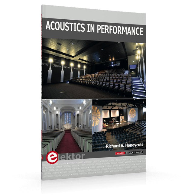
Elektor Publishing Acoustics in Performance
All you need to know about good acoustics and sound systems in performance and worship spaces! Everyone knows that the ability to hear music in balance and to understand speech is essential in any space used for performance or worship. Unfortunately, in the early 21st century, we find that buildings with good acoustics are the exception rather than the rule. Much of the fault leading to this result can be traced to the widespread perception that acoustics is a black art. In fact, scientific acoustics as developed in the last century is a well-defined engineering practice that can lead to predictable excellent results. A basic, non-engineering understanding of acoustics will help building owners, theater managers, ministers and teachers of music, performers, and other professionals to achieve their goals of excellent acoustics in venues with which they work. Performers having a basic understanding of acoustics will be able to make the most of the acoustics of the venue in which they perform. This book helps those responsible for providing good acoustics in performance and worship spaces to understand the variables and choices entailed in proper acoustic design for performance and worship. Practicing acoustical consultants will find the book a useful reference as well. The level of presentation is comfortable and straightforward without being simplistic. If correct acoustical principles are incorporated into the design, renovation, and maintenance of performance and worship venues, good acoustics will be the result.
€ 29,95
Leden: € 26,96
-

Elektor Digital Acoustics in Performance (E-book)
All you need to know about good acoustics and sound systems in performance and worship spaces! Everyone knows that the ability to hear music in balance and to understand speech is essential in any space used for performance or worship. Unfortunately, in the early 21st century, we find that buildings with good acoustics are the exception rather than the rule. Much of the fault leading to this result can be traced to the widespread perception that acoustics is a black art. In fact, scientific acoustics as developed in the last century is a well-defined engineering practice that can lead to predictable excellent results. A basic, non-engineering understanding of acoustics will help building owners, theater managers, ministers and teachers of music, performers, and other professionals to achieve their goals of excellent acoustics in venues with which they work. Performers having a basic understanding of acoustics will be able to make the most of the acoustics of the venue in which they perform. This book helps those responsible for providing good acoustics in performance and worship spaces to understand the variables and choices entailed in proper acoustic design for performance and worship. Practicing acoustical consultants will find the book a useful reference as well. The level of presentation is comfortable and straightforward without being simplistic. If correct acoustical principles are incorporated into the design, renovation, and maintenance of performance and worship venues, good acoustics will be the result.
€ 24,95
Leden: € 22,46
-

Great Scott Gadgets Acryl behuizing voor HackRF SDR
Deze doorzichtige acryl behuizing is de officiële behuizing voor het HackRF One/Pro board. Hij kan de standaard zwarte plastic behuizing van de HackRF One/Pro vervangen. Montage-instructies Gebruik een plectrum of spudger om de HackRF One/Pro printplaat uit de zwarte plastic behuizing te halen. Steek een lange schroef in elke hoek van het onderste acrylpaneel. Zet elke lange schroef vast met een kort afstandsstuk (5 mm) aan de tegenoverliggende kant van het paneel. Plaats de HackRF One/Pro printplaat (naar boven gericht) bovenop het onderpaneel en steek de uiteinden van de lange schroeven door de bevestigingsgaten in de hoeken van de print. Zet de printplaat vast met een lang afstandsstuk (6 mm) in elke hoek. Plaats het bovenste acrylpaneel op de printplaat en lijn de uitsparingen uit met de extension headers op de print. Zet elke hoek vast met een korte schroef. Opmerking: Niet te strak aandraaien! Na elke stap alleen met de hand aandraaien.
€ 19,95
Leden: € 17,96
-

Elektor Digital Advanced Control Robotics (E-book)
If you enjoy DIY electronics, projects, software and robots, you’ll find this book intellectually stimulating and immediately useful. With the right parts and a little guidance, you can build robot systems that suit your needs more than overpriced commercial systems can. 20 years ago, robots based on simple 8-bit processors and touch sensors were the norm. Now, it’s possible to build multi-core robots that can react to their surroundings with intelligence. Today’s robots combine sensor readings from accelerometers, gyroscopes and computer vision sensors to learn about their environments. They can respond using sophisticated control algorithms and they can process data both locally and in the cloud. This book, which covers the theory and best practices associated with advanced robot technologies, was written to help roboticists, whether amateur hobbyist or professional, take their designs to the next level. As will be seen, building advanced applications does not require extremely costly robot technology. All that is needed is simply the knowledge of which technologies are out there and how best to use each of them. Each chapter in this book will introduce one of these different technologies and discuss how best to use it in a robotics application. On the hardware side, we’ll cover microcontrollers, servos, and sensors, hopefully inspiring you to design your own awe-inspiring, next-generation systems. On the software side, we’ll cover programming languages, debugging, algorithms, and state machines. We’ll focus on the Arduino, the Parallax Propeller, Revolution Education PICAXE and projects I’ve with which I’ve been involved, including the TBot educational robot, the PropScope oscilloscope, the 12Blocks visual programming language, and the ViewPort development environment. In addition, we’ll serve up a comprehensive introduction to a variety of essential topics, including output (e.g. LEDs, servo motors), and communication technologies (e.g. infrared, audio), that you can use to develop systems that interact to stimuli and communicate with humans and other robots. To make these topics as accessible as possible, handy schematics, sample code and practical tips regarding building and debugging have been included. Hanno Sander Christchurch, New Zealand
€ 24,95
Leden: € 22,46
-
Eleshop AE970D Soldeerstation (80 W)
Soldeerstation voor precisiesolderen met actief verwarmde soldeerstift Het AE970D soldeerstation is een krachtig 80 W apparaat om te kunnen solderen met een snelle opwarming. Het brede temperatuurbereik van 150-550°C zorgt ervoor dat hij aan al uw soldeerwensen kan voldoen. Dankzij de krachtige plug-and-play geïntegreerde actieve soldeerstift kan de AE970D binnen 9 seconden het smeltpunt bereiken. Gepatenteerde close-loop automatische en constante temperatuurregeling zorgt ervoor dat er gesoldeerd kan worden met veel stabiliteit, uitstekende prestaties en een hoge nauwkeurigheid. Kenmerken Een vermogen van 80 W voor een snelle opwarming. Breed temperatuurbereik van 150-550°C (302-1022°F) om aan al uw soldeerwensen te kunnen voldoen. Hoogwaardige plug-and-play geïntegreerde actieve soldeerstift, kan het smeltpunt binnen 9 seconden bereiken. Gepatenteerde close-loop automatische en constante temperatuurregeling, wat veel stabiliteit, uitstekende prestaties en een hoge nauwkeurigheid garandeert. Specificaties Vermogen 80 W Voedingsspanning 110 VAC / 230 VAC Uitgangsspanning 25 VAC Temperatuurbereik 150-550°C (302-1022°F) Verwarmingselement Geïntegreerde actieve verwarming uit de T80-serie Temperatuurstabiliteit ±1°C/±1.8°F (bij temperatuur > 200°C/400°F) Weerstand van stift naar aarde < 2 Ω Spanning van stift naar aarde < 2 mV Lengte netsnoer 1 m Kabellengte naar soldeerbout 1,2 m Afmetingen 148 x 120 x 85 mm Gewicht (basis unit) 1,33 kg Inbegrepen Basis unit Soldeerbout incl. soldeerstift T80-D12 IJzeren standaard Messing wolbedje Handleiding
€ 95,00
-

Elektor Digital Alimentation électrique autonome (PDF)
ÉLECTRICITÉ PHOTOVOLTAÏQUE = ÉLECTRICITÉ GRATUITE Nous sommes désormais plus qu'heureux de poursuivre nos recherches sur notre propre autonomie et de veiller à ce que notre production électrique photovoltaïque soit appropriée ! D'abord on en rêve, puis vient l'étape du calcul : comparer le coût du kilowattheure d'origine du nucléaire (environnement à partir de centimes d'euro) et le calcul du kilowattheure d'origine photovoltaïque (l'environnement de 22 centimes de l'euro*), et nous saurons où en sont nos motivations d'écocitoyens. Gérard Guihéneuf, l'auteur de ce nouveau livre, pense qu'il ne faut pas se contenter d'aligner chiffres et idées. La nouvelle approche du processus de création d'entreprise se base sur la compréhension et les dimensions des installations des bâtiments domestiques dans le domaine public en 2009 et sur l'actualité des techniques et pratiques de réponse aux questions qui se posent lors de l'électrification des le site isolé ! La conception de projets simples, comme un contexte domestique, et d'un commentaire électrique standard, comme un système d'énergie photovoltaïque, trois emplacements réguliers : un abri dans le jardin, un garage et un mobil-home. L'économie est spectaculaire lorsqu'il s'agit de composants électroniques et d'assemblages de certains constituants essentiels, car les régulateurs de charge, les onduleurs et les panneaux solaires ne suffisent pas à l'entretien autonome du site. Si vous souhaitez en savoir plus sur l'électrification professionnelle de votre chantier, vous pouvez en savoir plus sur les dimensions des éléments constitutifs sans sacrifier l'efficacité ! Vous pouvez également utiliser la copie du Gerber et du Sprint Layout pour les circuits imprimés de la livrée. *avec les batteries en cours de reconditionnement lors de la panne photovoltaïque en cours et dans les vingt-cinq
€ 24,95
Leden: € 22,46
-

Elektor Digital Analogue Video (E-book)
This book is intended for electronics enthusiasts and professionals alike, who want a much deeper understanding of the incredible technology conquests over the pre-digital decades that created video. It details evolution of analogue video electronics and technology from the first electro-mechanical television, through advancements in Cathode Ray Tubes, transistor circuits and signal processing, up to the latest analogue, colour-rich TV, entertainment devices and calibration equipment. Key technological advances that enabled monochrome video and, eventually, colour are explained. The importance, compromises and techniques of maintaining crucial backward legacy compatibilities are described. The generation, signal processing and playback of analogue video signals in numerous capture, display, recording and playback devices together with operating principles and practices are examined. Technical and, often, political merits and deficiencies of key national and international video standards are highlighted. Several formats are shown to win and ultimately to co-exist. This book begins at fairly basic levels; concepts are introduced with human physiological perceptions of light and colour explained. This leads to the subject matter of luminance and chrominance; their equations and the circuits to process. There is full, detailed analysis of waveform shapes and timings inside video equipment and relevant popular connections e.g. S-video. Several analogue video projects which you can build yourself are also included in this book; with schematics, circuit board layouts and calibration steps to help you obtain the best results. The book makes use of many colour pages where the subject matter demands it (e.g. test cards). If you really want a deeper understanding of analogue video then this book is for you!
€ 24,95
Leden: € 22,46
-

Andonstar Andonstar AD1605 4K HDMI Digitale Microscoop
De Andonstar AD1605 4K Digitale Microscoop heeft een HD sensor van 14 megapixels, een oversized metalen voet en een verstelbare beugel. Met de 4K ultra HD beeldsensor kun je foto's van hoge kwaliteit maken en ultra-heldere video's opnemen. Deze 4K digitale microscoop bezit een vergroting tot 150x. Met een statiefmaat van 37,5 x 25 x 47 cm biedt hij een grote werkruimte die ideaal is voor assemblage, inspectie, training, real-time bekijken, beeldopname en videodocumentatie. Je kunt er de soldeerverbinding van een printplaat mee controleren, of de minuscule structuur van een munt, juweel, textiel, huid, insect, enz.. Features 14 MP HD sensor providing clear images of high quality Deep depth of field making images sharp and clear Oversized metal base providing large working space Wide focus range from 5 to 29 cm Adjustable metal bracket for easy adjustment of magnification and object distance Image capture & video record function for convenient documentation of work UV Filter to protect the lens from the oil, heat, dirt or dust during soldering or repair IR remote control for easy operation and avoid the shake of the microscope with the button playing Memory card with up to 32 GB storage (not included in the package) Applicaties Smartphone reparatie PCB controlle Planten & insecten Miniatuur kunst en handwerk Drukwerk / Textiel Assemblage Antiek authenticatie Bekijken van juwelen Horloge reparatie Zelfbouw Specificaties Image sensor 14 MP Video output 3840x2160 (30fps)2560x1440 (24fps)1920x1080 (60fps/30fps) Video formaat MP4 Vergroting Tot 150x (29 inch HDMI monitor) Foto resolutie Max. 12 MP (4032x3024) Foto formaat JPG Focus range 5-29 cm Frame Rate Max. 60fps Video interface HDMI Geheugenopslag microSD card (tot 32 GB) PC ondersteuning Nee Voeding 5 V DC Lichtbron 2 LEDs in de standaard Standaard afmetingen 37,5 x 25 x 47 cm Gewicht 5,5 kg Inbegrepen 1x Andonstar AD1605 Digitale Microscoop 1x Metalen standaard 1x UV filter 1x IR afstandbediening 1x Switch kabel 1x Voedingsadapter 1x Instructie manual
€ 349,00
-

Andonstar Andonstar AD407 7" HDMI Digitale Microscoop
Onderzoek je schakelingen met hoge precisie en soldeer zelfs de kleinste SMD's en onderdelen zonder problemen. Features De multifunctionele HDMI Digitale Microscoop heeft Full HD, comfortabele beeldschermruimte, een verbeterde ergonomie, meerdere uitgangssignalen met verschillende resoluties. De kantelhoek van de brede LCD monitor is instelbaar. Wordt geleverd met afstandsbediening. Kan als zelfstandig apparaat worden gebruikt. Specificaties Beeldscherm 7 inch (17,8 cm) Beeldsensor 4 MP Video output UHD 2880x2160 (24fps)FHD 1920x1080 (60fps/30fps)HD 1280x720 (120fps) Video formaat MP4 Vergrotingsfactor Tot 270 keer (27 inch HDMI monitor) Foto resolutie Max. 12 MP (4032x3024) Foto formaat JPG Focus bereik Min. 5 cm Frame snelheid Max. 120 fps (onder 600 Lux helderheid & HDP120) Video interface HDMI Opslag microSD card (tot 32 GB) Voeding 5 V DC Lichtbron 2 LED's met standaard Afmetingen 20 x 12 x 19 cm Inbegrepen 1x Andonstar AD407 Digitale Microscoop 1x Metalen statief met 2 LED's 1x Optische beugel 1x UV-filter 1x IR afstandsbediening 1x Verloopkabel 1x Voedingsadapter 1x HDMI kabel 2x Schroeven 1x Schroevendraaier 1x Gebruiksaanwijzing Downloads Manual Model vergelijking AD407 AD407 Pro AD409 AD409 Pro-ES Screen size 7 inch (17,8 cm) 7 inch (17,8 cm) 10,1 inch (25,7 cm) 10,1 inch (25,7 cm) Image sensor 4 MP 4 MP 4 MP 4 MP Video output 2160p 2160p 2160p 2160p Interfaces HDMI HDMI USB, HDMI, WiFi USB, HDMI, WiFi Video format MP4 MP4 MP4 MP4 Magnification Up to 270x Up to 270x Up to 300x Up to 300x Photo resolution Max. 4032x3024 Max. 4032x3024 Max. 4032x3024 Max. 4032x3024 Photo format JPG JPG JPG JPG Focus distance Min. 5 cm Min. 5 cm Min. 5 cm Min. 5 cm Frame rate Max. 120f/s Max. 120f/s Max. 120f/s Max. 120f/s Storage microSD card microSD card microSD card microSD card PC support No No Windows Windows Mobile connection No No WiFi + Measurement WiFi + Measurement Power source 5 V DC 5 V DC 5 V DC 5 V DC Light source 2 LEDs with the stand 2 LEDs with the stand 2 LEDs with the stand 2 LEDs with the stand Endoscope No No No Yes Stand size 20 x 12 x 19 cm 20 x 18 x 32 cm 18 x 20 x 30 cm 18 x 20 x 32 cm Weight 1,6 kg 2,1 kg 2,2 kg 2,5 kg
€ 185,13
-

Andonstar Andonstar AD407 Pro 7" HDMI Digitale Microscoop
De Andonstar AD407 Pro microscoop is geschikt voor diverse toepassingen, zoals het solderen van SMD's, of bij reparaties. De microscoop heeft een groot verstelbaar 7" LCD-scherm en wordt geleverd met een afstandsbediening. In vergelijking met de AD407 biedt de AD407 Pro een extra hoge standaard, wat het solderen van componenten nóg eenvoudiger maakt. Specificaties Schermgrootte 7 inch (17,8 cm) Beeldsensor 4 MP Video uitgang UHD 2880x2160 (24 fps)FHD 1920x1080 (60 fps/30 fps)HD 1280x720 (120 fps) Video formaat MP4 Vergroting Tot 270 keer (27 inch HDMI-monitor) Foto resolutie Max. 12 MP (4032x3024) Foto formaat JPG Focus afstand Min. 5 cm Frame rate Max. 120fps Video interface HDMI Opslag MicroSD-kaart (tot 64 GB) Voeding 5 V DC Verlichting 2 LED’s op de standaard Afmetingen standaard 20 x 18 x 32 cm Inbegrepen 1x Andonstar AD407 Pro Digital Microscope 1x Metalen standaard met 2 LED's 1x UV-filter (reeds gemonteerd in de lens) 1x IR-afstandsbediening 1x Switch kabel 1x Voedingsadapter 1x Instelsleutel 2x Metalen clips 1x HDMI-kabel 1x Manual Downloads Manual Vergelijking modellen AD407 AD407 Pro AD409 AD409 Pro-ES Schermgrootte 7 inch (17,8 cm) 7 inch (17,8 cm) 10,1 inch (25,7 cm) 10,1 inch (25,7 cm) Beeldsensor 4 MP 4 MP 4 MP 4 MP Video uitgang 2160p 2160p 2160p 2160p Interfaces HDMI HDMI USB, HDMI, WiFi USB, HDMI, WiFi Video formaat MP4 MP4 MP4 MP4 Vergroting Tot 270x Tot 270x Tot 300x Tot 300x Foto resolutie Max. 4032x3024 Max. 4032x3024 Max. 4032x3024 Max. 4032x3024 Foto formaat JPG JPG JPG JPG Focus afstand Min. 5 cm Min. 5 cm Min. 5 cm Min. 5 cm Frame rate Max. 120f/s Max. 120f/s Max. 120f/s Max. 120f/s Opslag MicroSD-kaart MicroSD-kaart MicroSD-kaart MicroSD-kaart PC-ondersteuning Nee Nee Windows Windows Ondersteuning mobiel Nee Nee WiFi + Metingen WiFi + Metingen Voeding 5 V DC 5 V DC 5 V DC 5 V DC Verlichting 2 LED's op de standaard 2 LED's op de standaard 2 LED's op de standaard 2 LED's op de standaard Endoscoop Nee Nee Nee Ja Afmetingen standaard 20 x 12 x 19 cm 20 x 18 x 32 cm 18 x 20 x 30 cm 18 x 20 x 32 cm Gewicht 1,6 kg 2,1 kg 2,2 kg 2,5 kg
€ 226,27


