Producten
-

Elektor Digital Elektor Septembre/Octobre 2025 (PDF) FR
Le téléchargement intégral de ce numéro est disponible pour nos membres GOLD et GREEN sur le site Elektor Magazine ! Pas encore membre ? Cliquez ici. carte émetteur-récepteur audio ESP32 (2)Transmission audio sans fil émetteur AM par inductionUtiliser les PIO du Pico dans un croquis Arduino les protocoles sans filUn guide technique suivi de satellites avec LoRaTinyGS, le réseau open source qui capte les données spatiales télécommande par sms compatible 4GContrôlez votre équipement à distance sonde haute vitesseMesure à haute impédance jusqu’à 200 MHz sur le vifKafka KrakenSDR tests de performance avec le RP2350Pico 2 : une vraie amélioration ? mesures de champ électrique sans contact (2)Un vibromètre laser pour l’analyse des vibrations de la membrane quartz et oscillateursAméliorer la précision des quartz grâce au choix des condensateurs démarrer en électroniqueCI audio originaux se lancer dans le codage d'un projet DIY SPECTRAN® V6 MobileAnalyseur de spectre temps réel modulaire et configurable pour des mesures fiables sur l’ensemble des plages de fréquences l’avenir de l’IA repose sur le siliciumEntretien avec Anastasiia Nosova nœud de capteurs autonome v2.0 (architecture du système)Plateforme de mesure autonome alimentée par énergie solaire, avec GPS intégré, LoRaWAN et plus encore positionnement précisTests du sondage de canal Bluetooth développement logiciel piloté par les tests voiture miniature contrôlée par SmartphoneWi-Fi + ESP32 + Smartphone = contrôle à distance 2025 : une odyssée de l’IAModèles de raisonnement en IA : la révolution de la chaîne de pensée contrôleur de charge solaire avec MPPT (3)Logiciel et mise en service caméra Web Raspberry Pi ZeroStreaming avec VPN ZeroTier
€ 10,95
-
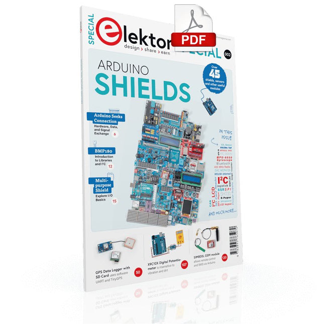
Elektor Digital Elektor Special: Arduino Shields (PDF) EN
Make your project dreams come true: an odometer for the hamster wheel, a fully automatic control of your ant farm with web interface, or the Sandwich-O-Mat – a machine that toasts and grills sandwiches of your choice. With the Arduino and the DIY or Maker movement, not only did entry into microcontroller programming become child's play, but a second development also took place: Resourceful developers brought small boards – so-called shields or modules – to the market, which greatly simplified the use of additional hardware. The small modules contain all the important electronic parts to be connected to the microcontroller with a few plug-in cables, eliminating the need for a fiddly and time-consuming assembly on the plug-in board. In addition, it is also possible to handle tiny components that do not have any connecting legs (so-called SMDs). Projects Discussed Arduino seeks connection BMP and introduction to libraries, I²C Learn I/O basics with the multi-purpose shield I²C LCD adapter and DOT matrix displays LCD keypad shield Level converter W5100: Internet connection I/O expansion shield Relays and solid-state relays The multi-function shield: A universal control unit Connecting an SD card reader via SPI Keys and 7-segment displays 16-bit ADC MCP4725 DAC 16-way PWM servo driver MP3 player GPS data logger using an SD card Touch sensor Joystick SHT31: Temperature and humidity VEML6070 UV-A sensor VL53L0X time-of-flight Ultrasonic distance meter MAX7219-based LED DOT matrix display DS3231 RTC Port expander MCP23017 433 MHz radio MPU-650 gyroscope ADXL345 accelerometer WS2812 RGB LEDs Power supply MQ-xx gas sensors CO2 gas sensor ACS712 current sensor INA219 current sensor L298 motor driver MFRC522 RFID 28BYJ-48 stepper motor TMC2209 silent step stick X9C10x digital potentiometer ST7735 in a color TFT display e-Paper display Bluetooth Geiger counter SIM800L GSM module I²C multiplexer Controller Area Network
€ 11,95
Leden: € 10,76
-
Elektor Digital Elektor Special: Audio 2 (PDF)
Zelfbouw versterkers en luidsprekers Deze speciale uitgave staat vol met interessante bouwbeschrijvingen en achtergrondartikelen van internationaal gerenommeerde ontwerpers. Het gaat in alle gevallen om nieuwe, nog niet eerder gepubliceerde artikelen. Inhoudsopgave Buizenversterkers 30 Watt buizenversterker met variabele dempingsfactor 50 Watt super triode versterker 300 Watt buizen eindversterker Digibias: digitaal de ruststroom instellen en bewaken Luidsprekers Paper Hatt - klein maar fijn Origami M en C – compacte actieve subwoofer in twee smaken Meerweg open baffle systemen – basistheorie, ontwerp en meetmethode Moai – hightech uit Scandinavië OB3W – drieweg open-baffle dipool van formaat 1685a – compacte tweeweg vloerstaander ScanSpeak Vertigo – duizelingwekkend mooi driewegsysteem Halfgeleiderversterkers MinimA – minimalistische 120W klasse-B versterker Gebalanceerde voorversterker met actief wisselfilter RelaiXed – gebalanceerde voorversterker met relais
€ 15,90
Leden: € 14,31
-
Elektor Digital Elektor Special: Audio 5 (PDF)
Zelfbouw versterkers en luidsprekers Ook deze vijfde Audio Special staat weer vol met interessante bouwbeschrijvingen en achtergrondartikelen van internationaal gerenommeerde ontwerpers. Ook dit jaar weer de inmiddels bekende mix van buizenversterkers en luidsprekers, zodat er voor iedere zelfbouwer ongetwijfeld iets interessants te lezen of te bouwen valt. Het gaat in alle gevallen om nieuwe, nog niet eerder gepubliceerde artikelen. Inhoud Versterkers Classic Three voorversterker Lijnvoorversterker met 6C33 De Dirigent – buizenvoorversterker met actief scheidingsfilter Single ended KR300B stereo eindversterker 1 Watt gitaarversterker – voor huiskamer Single ended 211 triode versterker – met interstage trafo Dieper kijken in de uitgangstransformator Prelude voorversterker – minimalisme in optima forma Klik aan, klik uit schakelaar – een netschakelaar met legio toepassingen Luidsprekers Scheidingsfilters voor luidsprekerboxen – meer valkuilen dan je lief is Morel Elite 420 – actieve tweeweg boekenplank luidspreker All back – een verrassend veelzijdige compacte TL HATT-SE MkII Micro Monitor – kleine luidspreker met pit Silverado – een d’Appolito met pit Nebular Monitor – een compacte luidspreker met een groots geluid LBVS – zelfbouwklassieker van eigen bodem Solo 201 – er is maar één weg!
€ 17,50
Leden: € 15,75
-
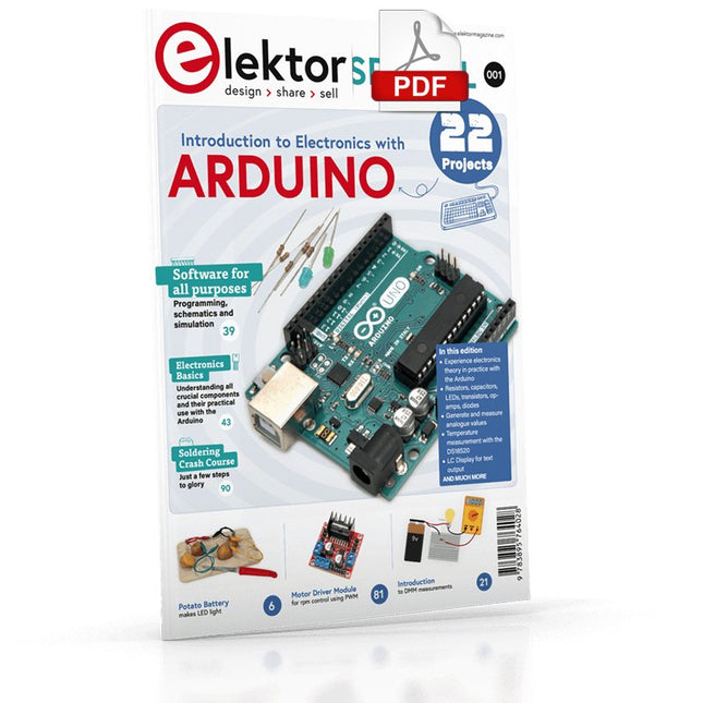
Elektor Digital Elektor Special: Introduction to Electronics with Arduino (PDF)
Although the Arduino isn’t a novelty any longer, there are still many beginners who want to try programming and development with a microcontroller, and to them, it is all new. All beginnings can be difficult, though they should be light and enjoyable. You do not need much or expensive equipment for the examples. The circuits are built on a small breadboard, and, if necessary, connected to an Arduino Uno, which you can program on a Windows PC. You will find clear examples of how to build all circuits, ensuring easy and error-free reproduction. Projects Discussed Current & Voltage – How it all began Arduino Hardware Arduino Programming The Electrical Circuit Measuring with the Multimeter Circuit Diagrams and Breadboards Creating Circuit Diagrams Breadboard Views with Fritzing Online Circuit Simulation Indispensable: Resistors (Part 1) Hands-on with Resistors (Part 2) Variable Resistors Diodes: One-way Street for Current The Transistor Switch Electromagnetism Relays and Motors op-amps: Operational Amplifiers Capacitors The NE555 Timer PWM and Analogue Values with Arduino 7-Segment Temperature Display Introduction to Soldering and LCDs
€ 11,95
Leden: € 10,76
-
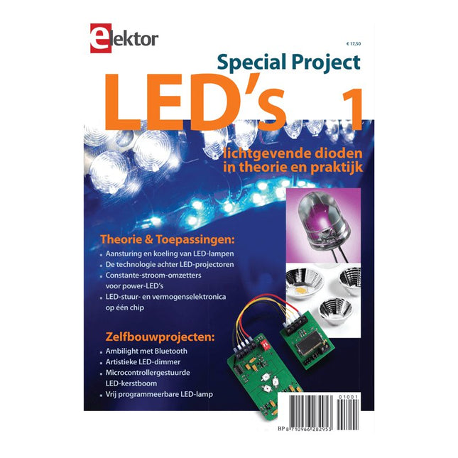
Elektor Digital Elektor Special: LED's 1 (PDF)
Lichtgevende dioden in theorie en praktijk Door verbetering van de lichtopbrengst en goedkopere productiemethoden is het toepassingsgebied van de LED uitgebreid van optische indicator tot energiezuinige lichtbron. Deze speciale Elektor-uitgave biedt niet alleen theoretische informatie, maar laat ook zien hoe en waar LED’s tegenwoordig toegepast worden. Bovendien bevat deze uitgave enkele beproefde elektronische schakelingen voor zelfbouw, zodat elke (aspirant)elektronicus zelf met LED’s aan de slag kan gaan. Een greep uit de inhoud Theorie & Toepassingen Aansturing en koeling van LED-lampen De technologie achter LED-projectoren Constante-stroom-omzetters voor power-LED’s LED-stuur- en vermogenselektronica op één chip Zelfbouwprojecten Ambilight met Bluetooth Artistieke LED-dimmer Microcontrollergestuurde LED-kerstboom Vrij programmeerbare LED-lamp
€ 17,50
Leden: € 15,75
-
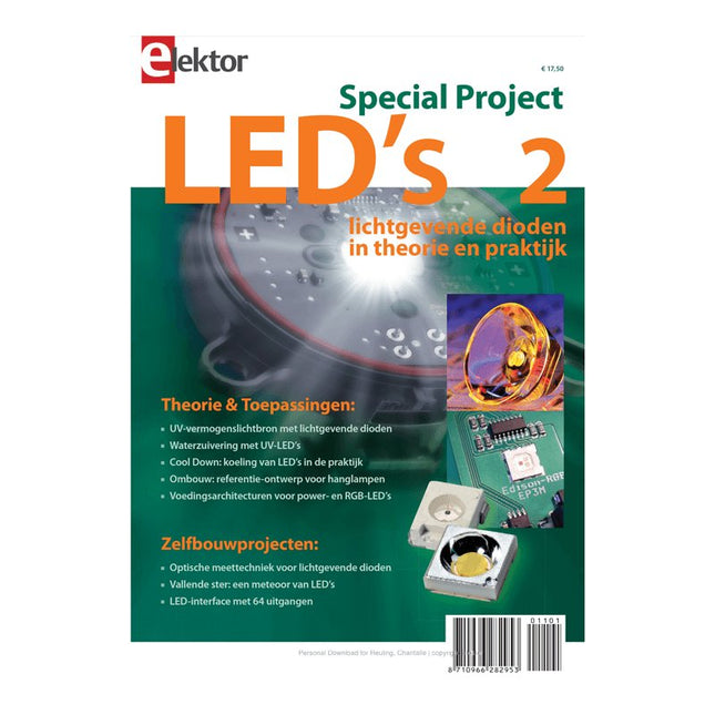
Elektor Digital Elektor Special: LED's 2 (PDF)
Lichtgevende dioden in theorie en praktijk Door verbetering van de lichtopbrengst en goedkopere productiemethoden is het toepassingsgebied van de LED uitgebreid van optische indicator tot energiezuinige lichtbron. Deze tweede Elektor LED Special biedt niet alleen theoretische informatie, maar laat ook zien hoe en waar LED’s tegenwoordig toegepast worden. Bovendien bevat deze uitgave enkele beproefde elektronische schakelingen voor zelfbouw, zodat elke (aspirant)elektronicus zelf met LED’s aan de slag kan gaan. Een greep uit de inhoud Theorie & Toepassingen UV-vermogenslichtbron met lichtgevende dioden Waterzuivering met UV-LED’s Cool Down: koeling van LED’s in de praktijk Aansturing van hoogvermogen-LED-verlichtingssystemen Ombouw: referentie-ontwerp voor hanglampen Multicolour-driver voor vermogens-LED’s Zelfbouwprojecten Optische meettechnieken voor lichtgevende dioden Vallende ster: een meteoor van LED’s LED-interface met 64 uitgangen
€ 17,50
Leden: € 15,75
-
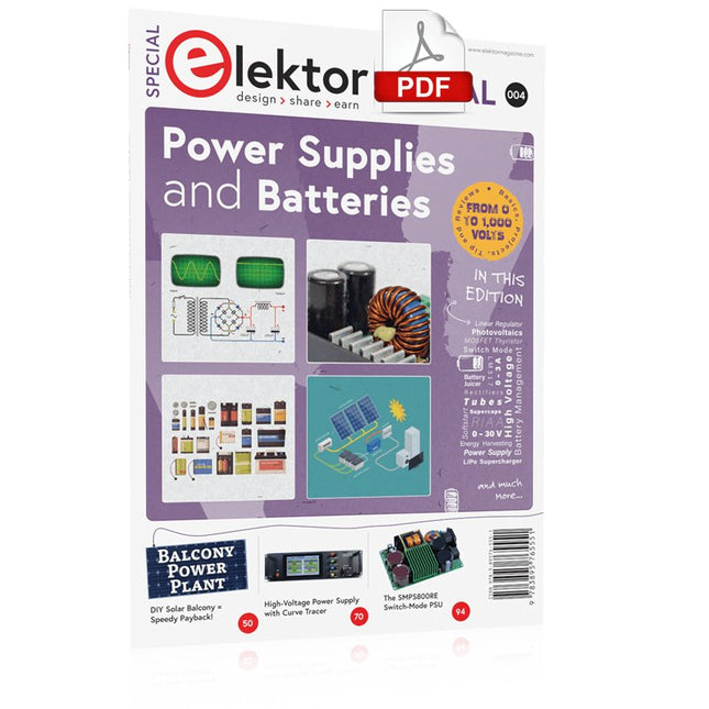
Elektor Digital Elektor Special: Power Supplies and Batteries (PDF)
Whatever the methods or even then financial means you have to make your circuits work, the power supply should rank high if not Number One in your considerations. The design block simply called “power supply” is hugely underrated both in electronics creation and repair. Yet, the “PSU” has enormous diversity and comes in wildly differing guises like AC/DC, generator, battery (rechargeable or not), PV panel, benchtop, linear or switch-mode, to mention but a few. The output ranges are also staggering like nano-amps to kiloamps and the same for voltages.This special covers the features and design aspects of power supplies.ContentsBasics Battery ManagementWhat to be aware of when using (Lithium) batteries. Fixed-Voltage Power Supply using Linear RegulatorsThe best result right after batteries. Light Energy HarvestingA small solar panel is used in an energy harvesting project to manage and charge four AAA cells. Mains Powered Adapter DesignBasic circuits and tips for transformers, rectification, filtering and stabilization. LM317 Soft StartThe high inrush current pulse should be avoided. Controllable RectifiersSome suggestions to keep the power loss in the linear regulator as low as possible. Components Worksheet: The LM117 / LM217 / LM317 Voltage Regulators SupercapsLow voltage but lots of current… or not? Reviews JOY-iT RD6006 Benchtop Power Supply Kit Siglent SDL1020X Programmable DC Electronic Load Projects Balcony Power PlantDIY solar balcony = speedy payback! DIY LiPo Supercharger KitFrom handcrafted to mass market Dual-Anode MOSFET ThyristorFaster and less wasteful than the old SCR Battery JuicerDo not throw away, squeeze! High-Voltage Power Supply with Curve TracerGenerate voltages up to 400 V and trace characteristics curves for valves and transistors High Voltage Supply for RIAAFor RIAA tube preamps and other applications. MicroSupplyA lab power supply for connected devices Phantom Power Supply using Switched CapacitorsVoltage tripler using three ICs The SMPS800RE Switch-Mode Supply for the Elektor Fortissimo-100Reliable, light and affordable Soft Start for PSUBe nice to your power supply – and its load UniLab 20-30 V, 3 A compact switch-mode lab power supply Tips Soft Start for Step-Down Switching Regulators Low Loss Current Limit Powerbank Surprise A Virtual Ground Battery Maintainer Battery Pack Discharger Connecting Voltage Regulators in Parallel
€ 11,95
Leden: € 10,76
-
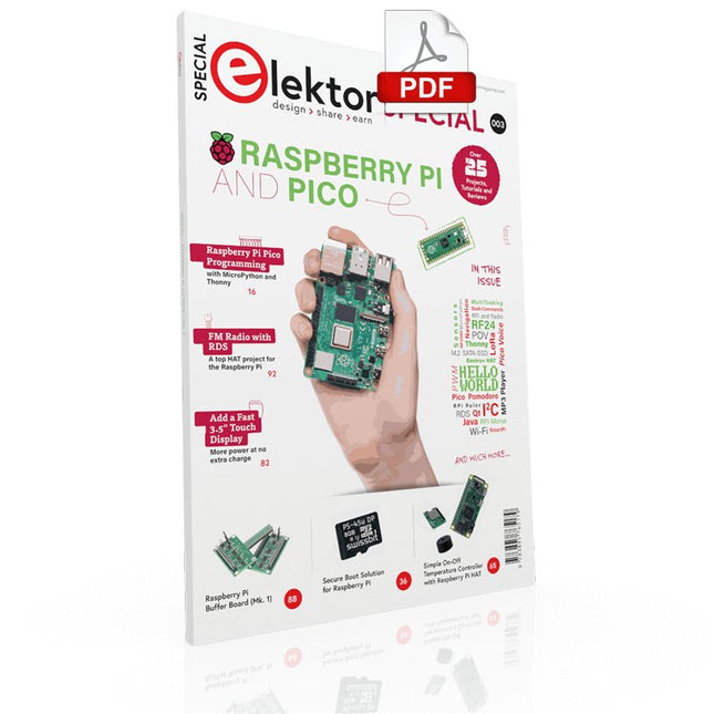
Elektor Digital Elektor Special: Raspberry Pi and Pico (PDF)
Contents Projects PicoVoiceVoice alienation and sound effects with the Raspberry Pi Pico Navigation with Vibration Feedback POV Display Pulse Width Modulation (PWM) with the Raspberry Pi Pico Wi-Fi with the Raspberry Pi Pico 'Hello World' from the Raspberry Pi Pico and RP2040A look at the Raspberry Pi Foundation’s first microcontroller Simple On-Off Temperature Controller with Raspberry Pi HAT Multitasking with the Raspberry PiShowcase: a traffic lights controller The Raspberry Pi Ruler GadgetFun with a time-of-flight sensor Raspberry Pi Buffer Board (Mk. 1)Never blow up the I/O again FM radio with RDSA top HAT project for the Raspberry Pi LoRa with the Raspberry Pi PicoFun with MicroPython! Tutorials Qt for the Raspberry Pi Raspberry Pi Pico Programmingwith MicroPython and Thonny Raspberry Pi Full StackRPi and RF24 at the heart of a sensor network Raspberry Pi Bash Command Cheat Sheet Community Java on the Raspberry PiAn interview with Frank Delporte Reviews Introducing the New Raspberry Pi Pico W, H, and WH Secure Boot Solution for Raspberry PiRetrofit security at a reasonable price Review: SmartPi – Smart Meter Extension for Raspberry Pi Review: The Enviro+ Raspberry Pi HATMeasuring environmental data with Raspberry Pi and the HAT Enviro+ Review: Meet the Raspberry Pi 4All new but still good? Raspberry Pi Gets a Fast 3.5' Touch DisplayMore power at no extra charge Book Launch: Raspberry Pi for Radio Amateurs
€ 11,95
Leden: € 10,76
-

Elektor Special: Robotics and Automation
AI in Practice Dive into the fascinating world of robotics and automation! This Elektor Special shows you how to build your own robots with creativity, a little know-how, and affordable technology. From your first DIY project with Arduino or Raspberry Pi to intelligent systems with AI – this issue makes modern robotics understandable and accessible. Discover practical instructions, inspiring projects, and exciting insights into the maker scene. Learn how experimentation, community, and openness give rise to true innovation – and why robotics is so much more than just a technical hobby. Contents Imagination turns into reality Arduino-controlled Drawing Robot GalaxyRVR Mars Rover Kit for Arduino YDLIDAR X4Pro Lidar xHuskyLens AI Camera DOF Robot Arm with Raspberry Pi Pico Manufacturing Robots with Fischertechnik Pneumatic Industrial Robot Why Do We Keep Building Robot Dogs? Elektor Mini-Wheelie Robot Vehicles and Autonomous Driving
€ 19,95
Leden: € 17,96
-

Elektor Digital Elektor Special: Robotics and Automation (PDF)
AI in Practice Dive into the fascinating world of robotics and automation! This Elektor Special shows you how to build your own robots with creativity, a little know-how, and affordable technology. From your first DIY project with Arduino or Raspberry Pi to intelligent systems with AI – this issue makes modern robotics understandable and accessible. Discover practical instructions, inspiring projects, and exciting insights into the maker scene. Learn how experimentation, community, and openness give rise to true innovation – and why robotics is so much more than just a technical hobby. Contents Imagination turns into reality Arduino-controlled Drawing Robot GalaxyRVR Mars Rover Kit for Arduino YDLIDAR X4Pro Lidar xHuskyLens AI Camera DOF Robot Arm with Raspberry Pi Pico Manufacturing Robots with Fischertechnik Pneumatic Industrial Robot Why Do We Keep Building Robot Dogs? Elektor Mini-Wheelie Robot Vehicles and Autonomous Driving
€ 14,95
Leden: € 13,46
-

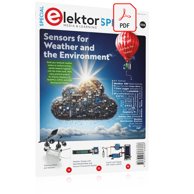
Elektor Special: Sensors for Weather and the Environment
Build your textbook weather station or conduct environmental research together with the whole world. With many practical projects for Arduino, Raspberry Pi, NodeMCU, ESP32, and other development boards. Weather stations have enjoyed great popularity for decades. Every current and even every long discontinued electronics magazine has regularly featured articles on building your own weather station. Over the years, they have become increasingly sophisticated and can now be fully integrated into an automated home — although this often requires loyalty to an (expensive) brand manufacturer across all components. With your own weather and environmental data, you can keep up and measure things that no commercial station can. It’s also fun: expand your knowledge of electronics, current microcontroller development boards and programming languages in a fun and meaningful way. For less than 10 euros you can get started and record your first environmental data — with time and growing interest, you will continue to expand your system. In this Edition Which Microcontroller Fits My Project? The Right Development Environment Tracking Wind and Weather Weather Display with OpenWeatherMap and Vacuum Fluorescent Display Volatile Organic Compounds in the Air We Breathe Working with MQ Sensors: Measuring Carbon Monoxide — Odorless but Toxic CO2 Traffic Light with ThingSpeak IoT Connection An Automatic Plant Watering System Good Indoor Climate: Temperature and Humidity are Important criteria Classy Thermometer with Vintage Tube Technology Nostalgic Weather House for the Whole Family Measuring Air Pressure and Temperature Accurately Sunburn Warning Device DIY Sensor for Sunshine Duration Simple Smartphone Says: Fog or Clear View? Identifying Earthquakes Liquid Level Measurement for Vessels and Reservoirs Water pH Value Measurement Detecting Radioactive Radiation GPS: Sensor Location Service Across the Globe Saving and Timestamping Log Files on SD Cards LoRaWAN, The Things Network, and ThingSpeak Operating a LoRaWAN Gateway for TTN Defying "Wind and Weather" Mega Display with Weather Forecasz
€ 19,95
Leden: € 17,96
-
Elektor Digital Elektor Special: Sensors for Weather and the Environment (PDF)
Build your textbook weather station or conduct environmental research together with the whole world. With many practical projects for Arduino, Raspberry Pi, NodeMCU, ESP32, and other development boards. Weather stations have enjoyed great popularity for decades. Every current and even every long discontinued electronics magazine has regularly featured articles on building your own weather station. Over the years, they have become increasingly sophisticated and can now be fully integrated into an automated home — although this often requires loyalty to an (expensive) brand manufacturer across all components. With your own weather and environmental data, you can keep up and measure things that no commercial station can. It’s also fun: expand your knowledge of electronics, current microcontroller development boards and programming languages in a fun and meaningful way. For less than 10 euros you can get started and record your first environmental data — with time and growing interest, you will continue to expand your system. In this Edition Which Microcontroller Fits My Project? The Right Development Environment Tracking Wind and Weather Weather Display with OpenWeatherMap and Vacuum Fluorescent Display Volatile Organic Compounds in the Air We Breathe Working with MQ Sensors: Measuring Carbon Monoxide — Odorless but Toxic CO2 Traffic Light with ThingSpeak IoT Connection An Automatic Plant Watering System Good Indoor Climate: Temperature and Humidity are Important criteria Classy Thermometer with Vintage Tube Technology Nostalgic Weather House for the Whole Family Measuring Air Pressure and Temperature Accurately Sunburn Warning Device DIY Sensor for Sunshine Duration Simple Smartphone Says: Fog or Clear View? Identifying Earthquakes Liquid Level Measurement for Vessels and Reservoirs Water pH Value Measurement Detecting Radioactive Radiation GPS: Sensor Location Service Across the Globe Saving and Timestamping Log Files on SD Cards LoRaWAN, The Things Network, and ThingSpeak Operating a LoRaWAN Gateway for TTN Defying "Wind and Weather" Mega Display with Weather Forecasz
€ 14,95
Leden: € 13,46
-

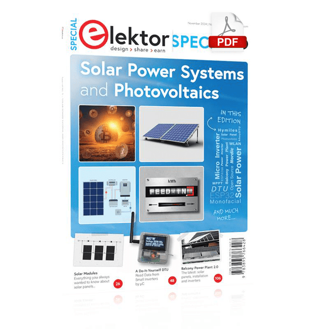
Elektor Special: Solar Power Systems and Photovoltaics
As demand for solar panel installation has risen sharply, especially for installations larger than balcony power plants, the order books of solar companies are full. If you ask for a quote today, you may have to wait a while, if your request isn't simply postponed indefinitely. Another consequence of the solar boom is that some companies are charging very high prices for installations. Yet there is an obvious and radical solution to the problem of excessive prices: Do it yourself, as the English say. The price of materials is currently affordable, and it's the ideal time for those who do the work themselves. They couldn't save more. Add to this the satisfaction of doing something useful, both economically and ecologically, and the pleasure of building yourself. In this special issue, you'll find a wide selection of Elektor assemblies, from solar panel controllers to solar water heaters and solar panel orientation systems. The issue also contains practical information on solar panel installation and the technology behind them. Finally, there are a number of articles on the subject of balcony power plants, from how to install them to how to connect them to the Internet... Contents BASICS Dimensioning Photovoltaic Panel ArraysAn introduction to photovoltaic energy and the commonest techniques,followed by simplified calculation models and setup guidelines. Light Sensor TechnologyMeasuring daylight using LEDs. Solar Power Made SimpleSolar charging with and without a controller. Cable Cross-sections and Energy Losses in Solar SystemsKey considerations on the minimum values to respect for electricalcurrent in solar panel cabling. Solar ModulesEverything you always wanted to know about solar panels... Ideal Diode ControllerDiode Circuits with Low Power Dissipation. TIPS Tracking for Solar Modules zBot Solar/Battery Power Supply Solar Cell Array Charger with Regulator Solar Cell Voltage Regulator Solar-Powered Night Light Alternative Solar Battery Charger PROJECTS Energy LoggerMeasuring and Recording Power Consumption. Tiny Solar SupplySunlight In, 3.3 V Out. A Do-It-Yourself DTURead Data from Small Inverters by μC. Solar ChargerPortable energy for people on the move. Solar Thermal Energy RegulatorMaximum power point tracking explored. 2-amp Maximum Power Tracking ChargerSolar Power To The Max. Computer-driven HeliostatFollow the sun or the stars. Garden LightingUsing solar cells. Solar Panel Voltage Converter for IoT DevicesYes we CAN exploit indoor lighting. Travel ChargerFree power in the mountains. Solar Cell Battery Charger/MonitorWith protection against deep discharge. Solar-powered Battery ChargerPIC12C671 avoids overcharging and deep charging. Converters for Photovoltaic PanelsContributed by TME (Transfer MultisortElektronik). Solar Charging RegulatorFor panels up to 53 watts. Solar-Powered ChargerFor lead-acid batteries. CAN Bus + Arduino for Solar PV Cell MonitoringDetect and locate serviceable panels in large arrays. Balcony Power Plant 2.0The latest: solar panels, installation and inverters
€ 19,95
Leden: € 17,96
-
Elektor Digital Elektor Special: Solar Power Systems and Photovoltaics (PDF)
As demand for solar panel installation has risen sharply, especially for installations larger than balcony power plants, the order books of solar companies are full. If you ask for a quote today, you may have to wait a while, if your request isn't simply postponed indefinitely. Another consequence of the solar boom is that some companies are charging very high prices for installations. Yet there is an obvious and radical solution to the problem of excessive prices: Do it yourself, as the English say. The price of materials is currently affordable, and it's the ideal time for those who do the work themselves. They couldn't save more. Add to this the satisfaction of doing something useful, both economically and ecologically, and the pleasure of building yourself. In this special issue, you'll find a wide selection of Elektor assemblies, from solar panel controllers to solar water heaters and solar panel orientation systems. The issue also contains practical information on solar panel installation and the technology behind them. Finally, there are a number of articles on the subject of balcony power plants, from how to install them to how to connect them to the Internet... Contents BASICS Dimensioning Photovoltaic Panel ArraysAn introduction to photovoltaic energy and the commonest techniques,followed by simplified calculation models and setup guidelines. Light Sensor TechnologyMeasuring daylight using LEDs. Solar Power Made SimpleSolar charging with and without a controller. Cable Cross-sections and Energy Losses in Solar SystemsKey considerations on the minimum values to respect for electricalcurrent in solar panel cabling. Solar ModulesEverything you always wanted to know about solar panels... Ideal Diode ControllerDiode Circuits with Low Power Dissipation. TIPS Tracking for Solar Modules zBot Solar/Battery Power Supply Solar Cell Array Charger with Regulator Solar Cell Voltage Regulator Solar-Powered Night Light Alternative Solar Battery Charger PROJECTS Energy LoggerMeasuring and Recording Power Consumption. Tiny Solar SupplySunlight In, 3.3 V Out. A Do-It-Yourself DTURead Data from Small Inverters by μC. Solar ChargerPortable energy for people on the move. Solar Thermal Energy RegulatorMaximum power point tracking explored. 2-amp Maximum Power Tracking ChargerSolar Power To The Max. Computer-driven HeliostatFollow the sun or the stars. Garden LightingUsing solar cells. Solar Panel Voltage Converter for IoT DevicesYes we CAN exploit indoor lighting. Travel ChargerFree power in the mountains. Solar Cell Battery Charger/MonitorWith protection against deep discharge. Solar-powered Battery ChargerPIC12C671 avoids overcharging and deep charging. Converters for Photovoltaic PanelsContributed by TME (Transfer MultisortElektronik). Solar Charging RegulatorFor panels up to 53 watts. Solar-Powered ChargerFor lead-acid batteries. CAN Bus + Arduino for Solar PV Cell MonitoringDetect and locate serviceable panels in large arrays. Balcony Power Plant 2.0The latest: solar panels, installation and inverters
€ 14,95
Leden: € 13,46
-

Elektor Digital Elektor Summer Circuits 2022 (PDF)
Meer dan 50 schakelingen & projecten US-sirene Twee draai-encoders op één analoge ingang Digitale 220VAC-dimmer met Arduino Stroombron voor LED’s Vier schakelaars detecteren met één pin Kleine aan/uit-schakelaar met accucontrole Desinfectie-dispenser voor zelfbouw Eenvoudig elektronisch orgel Simpele stereoversterker Audiogestuurde schakelaar Gebalanceerd/ongebalanceerd-converter Extern netfilter Knoploze garagedeurbediening DI-box voor smartphone Pret met een looplicht Eenknops-thyristorbesturing Quasi-analoge belichtingstimer voor de donkere kamer Schakelingen bij de Hackster.io-community Analoge zonnebad-timer Weer een eendraads LCD-interface Simpele PWM-generator met AVR ATtiny13 Een tweede leven voor batterijen Aanraakschakelaar voor LED-verlichting Tester voor LED’s en DIP-schakelaars IR-afstandsbedieningstester Tester voor vermogens-halfgeleiders SPI voor WS2812(B)-LED’s Meten van vermogens-zelfinducties Eén stekker voor Raspberry Pi en Audio DAC Doe-het-zelf meetklem voor de LCR-meter Arduino-ampèremeter Tweevinger-orgel Ruisarme ADC-kalibrator DC/DC-boostconverter Twee potmeters op één digitale ingang Akoestische nabijheidssensor Batterijloze radiatorsensor Speurneus voor draadloze camera’s en microfoons Timer voor auto-binnenverlichting Kaarssimulator Digitale keukentimer Milliohm-meter Warmwatervertrager Eenvoudige lader voor twee (of meer) 18650-cellen Mini-frequentiereferentie Zuinige IR-schakelaar Hergebruik de telefoonlader van je auto Microfoon-voorversterker voor Arduino EMI-filters voor zelfbouw Elektronische dobbelsteen zonder MCU Vingercondensator Zelfladende flits-LED Ook in deze editie KiCad 6 – vijf interessante nieuwe functies Retrotronica – de Elektor SC/MP-computer Interview – kunst maken met elektriciteit Mijn eerste print – spring in het diepe... met KiCad Met slimme software de hardware minimaliseren Elektor Infographics – feiten en cijfers Nieuwe componenten van Analog Optimalisering van de signaalintegriteit – Industry 4.0 vereist vlekkeloos werkende interfaces7 Hexadoku – puzzelen voor elektronici
€ 9,95
-

Elektor Labs Elektor Super Servo Tester Kit
De Elektor Super Servo Tester kan servo's aansturen en servosignalen meten. Hij kan tot vier servokanalen tegelijkertijd testen. De Super Servo Tester wordt geleverd als bouwpakket. Alle onderdelen die nodig zijn om de Super Servo Tester in elkaar te zetten zijn inbegrepen in de set. Het bouwen van de kit vereist enige basisvaardigheid met solderen. De microcontroller is al geprogrammeerd. De Super Servo Tester beschikt over twee bedrijfsmodi: Control/Manual en Measure/Inputs. In de modus Control/Manual genereert de Super Servo Tester besturingssignalen op zijn uitgangen voor maximaal vier servo's, of voor de flight controller of ESC. De signalen worden ingeregeld door de vier potentiometers. In de modus Measure/Inputs meet de Super Servo Tester de servosignalen die op de ingangen zijn aangesloten. Deze signalen kunnen afkomstig zijn van bijvoorbeeld een ESC, een flight controller, of de ontvanger, of een ander apparaat. De signalen worden ook naar de uitgangen geleid om de servo's of de flight controller of ESC aan te sturen. De resultaten worden op het display weergegeven. Specificaties Operating modi Control/Manual & Measure/Inputs Kanalen 3 Servosignaal ingangen 4 Servosignaal uitgangen 4 Alarm Zoemer & LED Weergave 0,96" OLED (128 x 32 pixels) Ingangsspanning op K5 7 - 12 VDC Ingangsspanning op K1 5 - 7,5 VDC Ingangsstroom 30 mA (9 VDC op K5, en niets aangesloten op K1 en K2) Afmetingen 113 x 66 x 25 mm Gewicht 60 g Inbegrepen Weerstanden (0,25 W) R1, R3 1 k?, 5% R2, R4, R5, R6, R7, R9, R10 10 k?, 5% R8 22 ?, 5% P1, P2, P3, P4 10 k?, lin/B, verticale potentiometer Condensatoren C1 100 ?F 16 V C2 10 ?F 25 V C3, C4, C7 100 nF C5, C6 22 pF Halfgeleiders D1 1N5817 D2 LM385Z-2.5 D3 BZX79-C5V1 IC1 7805 IC2 ATmega328P-PU, geprogrammeerd LED1 LED, 3 mm, rood T1 2N7000 Diversen BUZ1 Piëzo-zoemer met oscillator K1, K2 2-rijige, 12-voudige pinheader, 90° K5 Barrel jack K4 1-rijige, 4-polige pinvoet K3 2-rijige, 6-voudige boxed pinheader S1 Schuifschakelaar DPDT S2 Schuifschakelaar SPDT X1 Kristal, 16 MHz 28-voudige DIP-voet voor IC2 Elektor printplaat OLED-scherm, 0,96", 128 x 32 pixels, 4-pins I²C-interface Links Elektor Magazine Elektor Labs
€ 59,95€ 49,95
Beste prijs
-
Elektor Publishing Elektronica echt niet moeilijk (deel 1, 2 en 3)
Elektronica moeilijk? De titel van dit boek geeft het antwoord! In deze 3-in-1-band wordt de elektronica vanuit de praktijk benaderd. Dat wil zeggen veel praktijk in de vorm van experimenten en een minimum aan theorie. Zo raakt u stap voor stap vertrouwd met de behandelde onderwerpen. Daarbij ontstaan gaandeweg ook een flink aantal praktisch bruikbare schakelingen. Het gaat bij de elektronicahobby tenslotte om het bouwen of uitdenken van allerlei praktische of leuke schakelingen. Aan het eind van elk deel is een aanhangsel opgenomen met aanvullende informatie en de gegevens van een groot aantal elektronische componenten, zodat na dit boek ook eigen ideeën en experimenten kunnen worden aangepakt. In deze 3-in-1-band zijn de eerste drie delen uit de serie “Elektronica echt niet moeilijk” samengevoegd: Deel 1: experimenten met gelijkstroom Deel 2: experimenten met wisselstroom Deel 3: experimenten met digitale techniek
€ 44,95
Leden: € 40,46
-

Elektor Digital Elektronica echt niet moeilijk (deel 1, 2 en 3) | E-book
Elektronica moeilijk? De titel van dit boek geeft het antwoord! In deze 3-in-1-band wordt de elektronica vanuit de praktijk benaderd. Dat wil zeggen veel praktijk in de vorm van experimenten en een minimum aan theorie. Zo raakt u stap voor stap vertrouwd met de behandelde onderwerpen. Daarbij ontstaan gaandeweg ook een flink aantal praktisch bruikbare schakelingen. Het gaat bij de elektronicahobby tenslotte om het bouwen of uitdenken van allerlei praktische of leuke schakelingen. Aan het eind van elk deel is een aanhangsel opgenomen met aanvullende informatie en de gegevens van een groot aantal elektronische componenten, zodat na dit boek ook eigen ideeën en experimenten kunnen worden aangepakt. In deze 3-in-1-band zijn de eerste drie delen uit de serie “Elektronica echt niet moeilijk” samengevoegd: Deel 1: experimenten met gelijkstroom Deel 2: experimenten met wisselstroom Deel 3: experimenten met digitale techniek
€ 34,95
Leden: € 31,46
-
Elektor Publishing Elektronica Kunst & Kunde 2
In Elektronica Kunst & Kunde worden alle onderwerpen behandeld die ook in standaard elektronica-leerboeken aan de orde komen, plus een groot aantal belangrijke maar vaak veronachtzaamde zaken. In dit tweede deel aandacht voor onder meer de volgende onderwerpen: phase-locked loop-schakelingen, opto-elektronica, busschakelingen, capacitieve belasting, bekabeling, interfacing timing, naaldpulsen, klokvertraging, monostabiele multivibratoren de IBM-PC en de Intel-fanilie, RS232-kabels, seriële poorten, ASCII, modems, SCSI, IPI, GPIB, parallele poorten, local-area-networks de 68000-microprocessorfamilie, perifere LSI-chips, geheugen, programmeerbare instrumenten prototypering, het ontwerpen van printplaten, wire-wrap-technieken, CAD/CAM technieken, de bouw van schakelingen HF-modules, vereenvoudigd ontwerp van HF-versterkers en high-speed schakelaars batterijen, accu's en zonnecellen; micropower-regelaars, -opamps en -microprocessoren methoden om de bandbreedte te beperken, middeling van signalen, lock-in versterkers, pulshoogte-analyse, 'multichannel-scaling'
€ 39,95
Leden: € 35,96
-

Elektor Digital Elektronica Kunst & Kunde 2 (E-book)
In Elektronica Kunst & Kunde worden alle onderwerpen behandeld die ook in standaard elektronica-leerboeken aan de orde komen, plus een groot aantal belangrijke maar vaak veronachtzaamde zaken. In dit tweede deel aandacht voor onder meer de volgende onderwerpen: phase-locked loop-schakelingen, opto-elektronica, busschakelingen, capacitieve belasting, bekabeling, interfacing timing, naaldpulsen, klokvertraging, monostabiele multivibratoren de IBM-PC en de Intel-fanilie, RS232-kabels, seriële poorten, ASCII, modems, SCSI, IPI, GPIB, parallele poorten, local-area-networks de 68000-microprocessorfamilie, perifere LSI-chips, geheugen, programmeerbare instrumenten prototypering, het ontwerpen van printplaten, wire-wrap-technieken, CAD/CAM technieken, de bouw van schakelingen HF-modules, vereenvoudigd ontwerp van HF-versterkers en high-speed schakelaars batterijen, accu's en zonnecellen; micropower-regelaars, -opamps en -microprocessoren methoden om de bandbreedte te beperken, middeling van signalen, lock-in versterkers, pulshoogte-analyse, 'multichannel-scaling'
€ 29,95
Leden: € 26,96
-

Elektor Digital Elektronica Zakboek (E-BOOK)
Dit boek is een naslagwerk met praktijkgeoriënteerde formules en tabellen – en geen leerboek met uitvoerige uitleg. De schrijver heeft ook voor gecompliceerde vraagstukken handzame verklaringen, benaderingsformules en rekenvoorbeelden ontwikkeld zonder daarbij zijn toevlucht tot simplificaties te nemen. De logische indeling in 10 hoofdstukken vergemakkelijkt het opzoeken en vinden van de gewenste thema’s. In elk hoofdstuk treft u steeds de vereiste wis- en natuurkundige formules aan alsmede de belangrijkste tabellen. • Gelijkstroomkringen (inclusief de beginselen van de elektrotechniek) • Wisselstroomkringen • Dioden (berekeningen, toepassingen en gelijkrichtschakelingen) • Bipolaire transistoren • Veldeffecttransistoren (met schemavoorbeelden en berekeningen) • Speciale componenten (zoals PTC, NTC, VDR) • Operationele versterkers en hun basisschakelingen • Vermogenselektronica • Meettechniek (nauwkeurigheid, correcties, analoge en digitale meetapparaten) • Digitale technieken en binaire signaalwaarden De verzameling formules omvat alle belangrijke details voor ingenieurs en technici in de elektrotechniek en elektronica die zich met onderzoek, ontwikkeling en service bezig houden. Daarnaast is het echter ook bedoeld als naslagwerk voor studenten en docenten in het technisch (beroeps)onderwijs – en zeker ook voor de serieuze hobbyist.
€ 29,95
Leden: € 26,96
-

Elektor Digital Elektronicavoedingen zonder stress (E-BOOK)
Eén ding hebben alle elektronische schakelingen en apparaten gemeen: de werking ervan staat of valt met de voeding. Alleen al daarom verdient deze deelschakeling speciale aandacht. Dit boek behandelt principes en schakelingen uit de praktijk van de voedingstechniek. Geheel in overeenstemming met de huidige trend gaat de auteur in het bijzonder in op 'mobiele' voedingen en op de techniek van schakelende voedingen. Ook wordt aandacht besteed aan het feit dat constante-stroombronnen ten opzichte van spanningsbronnen een steeds belangrijker rol gaan spelen. Naast de vereiste theoretische achtergronden en principes voor het ontwerpen en bouwen van eigen voedingsschakelingen biedt dit boek ook praktische toepassingsvoorbeelden, zoals het vervangen van defecte nettransformatoren, de voeding voor elektronica tijdens fietstochten of het aansturen van LED‘s in de verlichtingstechniek. Auteur Franz Peter Zantis is afgestudeerd als ingenieur communicatietechniek en houdt zich als elektronicus bezig met energie-installaties. Tijdens een onderzoeksproject heeft hij zich grondig verdiept in de stroomvoorziening van zelfstandig werkende apparaten en hij heeft talrijke artikelen over schakelende voedingen gepubliceerd.
€ 34,95
Leden: € 31,46
-
Elektor Classics Elex Archief (USB-stick)
Het tijdschrift Elex was van 1983 tot 1993 het kleine zusje van Elektor. In Elex werd elektronica op een niet moeilijke en leuke manier uitgelegd. Veel huidige Elektor-lezers zijn ooit begonnen met Elex. Elex is nostalgie. Dat blijkt uit de grote vraag die er steeds is gebleven naar de artikelen en schakelingen uit Elex. Daarom hebben we alle Elex-uitgaven in PDF-formaat op USB-stick gezet. Het gaat om in totaal 120 Elex-nummers, samen goed voor ruim 1400 artikelen, tips en trucs! Deze stick bevat, naast op informele wijze beschreven theorie, een schat aan eenvoudige en leuke schakelingen voor zelfbouw. Alle nummers zijn snel doorzoekbaar en gemakkelijk afdrukbaar.


