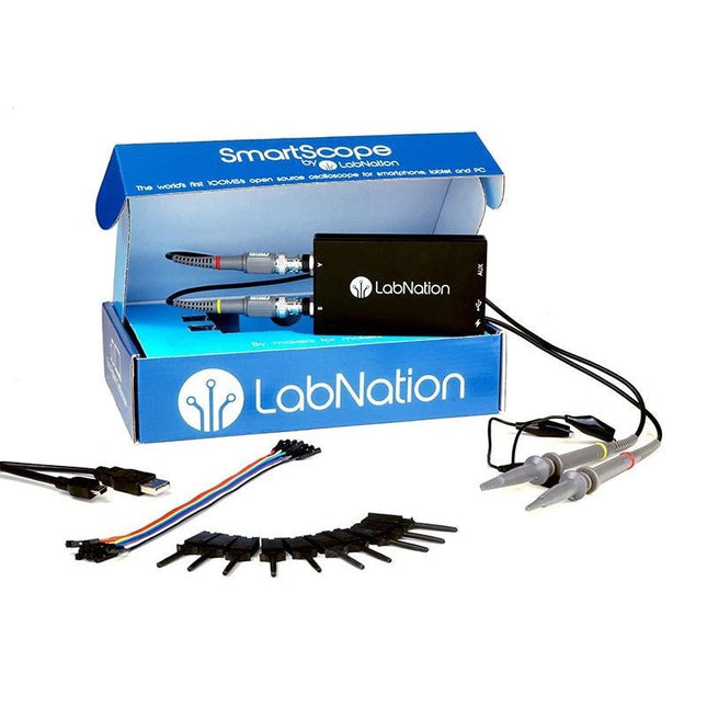
SmartScope is een compacte 2-kanaals USB-oscilloscoop met een bandbreedte van 30 MHz en een sampling rate van 2x 100 MSa/s. Het is compatibel met alle belangrijke platforms, waaronder Windows, macOS, Linux en Android. De bediening en weergave van meetsignalen gebeurt via smartphone, tablet of pc. Daarnaast zijn een logic analyzer en een signaalgenerator geïntegreerd.
Met de SmartScope ontwikkelt u uw digitale interfaces met behulp van de 100 MS/s logic analyzer. Met dit gereedschap kunt u elk gewenst signaal ontwerpen met behulp van Excel, en het vervolgens uploaden naar de ingebouwde Arbitrary Waveform Generator (AWG). Aan het eind legt u 100 miljoen keer per seconde de spanning vast op elk punt van uw ontwerp.
De software voor de ondersteuning van Windows / macOS / Linux / Android en exportformaten (Excel .csv / Matlab .mat) worden gegeven.
Kenmerken
Elk kanaal bemonsterd op 100 MHz/s
AC/DC-koppeling op analoge ingangen
100% geruisloos
64 Mbit RAM: x10000 zoom
Arbitraire golfvormgenerator
8 digitale ingangen bij 100 MS/s elk
4 digitale uitgangen van elk 100 MS/s
Externe voeding voor het geval uw mobiel geen stroom kan leveren.
Specificaties
Oscilloscope
Bandwidth
30 MHz (-3 dB point)
Sample rate
2 x 100 MS/s
Channels
2
Max pre-trigger position
16 x full scale
Max post-trigger position
Full scale
Max full voltage scale
10 V/div (±35 V input range)
Min full voltage scale
20 mV/div
Analog input range
-35 V, +35 V
Max input peak-to-peak
40 V
Signal coupling
AC / DC
Precision
8 bit
Input impedance
1 MΩ // 10 pF
Waverforms
200 waveforms/s
Data delay to host
<10 ms
Sample depth
Up to 4 million samples per channel
External trigger
Yes
Logic Analyzer
Input channels
8
Input impedance
100 kOhm // 2 pF to GND
Sample rate
100 MS/s
Logic level
1.8 V to 5.0 V
Diode protection
Bidirectional
Input data buffer
4 million samples
Waverforms
200 waveforms/s
Data delay to host
<10 ms
Protocol decoders
I²C, SPI, UART, I²S integrated User extensible
Wave Generator (Analog Output)
Output channels
1
Data rate
Up to 50 MS/s
Output level
0-3.3 V (Opamp driven)
Output buffer
Up to 2048 samples
Max slew rate
30 ns/V
Step
13 mV
Wave Generator (Digital Output)
Channels
4
Data rate
Up to 100 MS/s
Output level
3.3 V or 5 V (selectable)
Output buffer
Up to 2048 samples
Diode protected
Yes
Programmable Logic
USB controller
MicroChip PIC18F14K50
USB interface
PicKit3 or USB flashable
FPGA
Xilinx Spartan 6
FPGA interface
JTAG and USB flashable
Size & Weight
Dimensions
110 x 64 x 24.2 mm (L x W x D)
Weight
158 g
Case
Aluminium
Connectivity
Device/Host
mini USB included
Record waveforms
Store Matlab (.mat) or Excel (.csv) files through Dropbox
Analog
BNC 2 probes included
Digital
8 x 0.1" pitch, probes (included)
Sync
USB micro B-B
Power
USB micro B (optional)
Inbegrepen
1x SmartScope USB-oscilloscoop
2x Analog probes
1x Digital probe kabels
1x USB-kabel
Downloads
Software
GitHub
Wiki
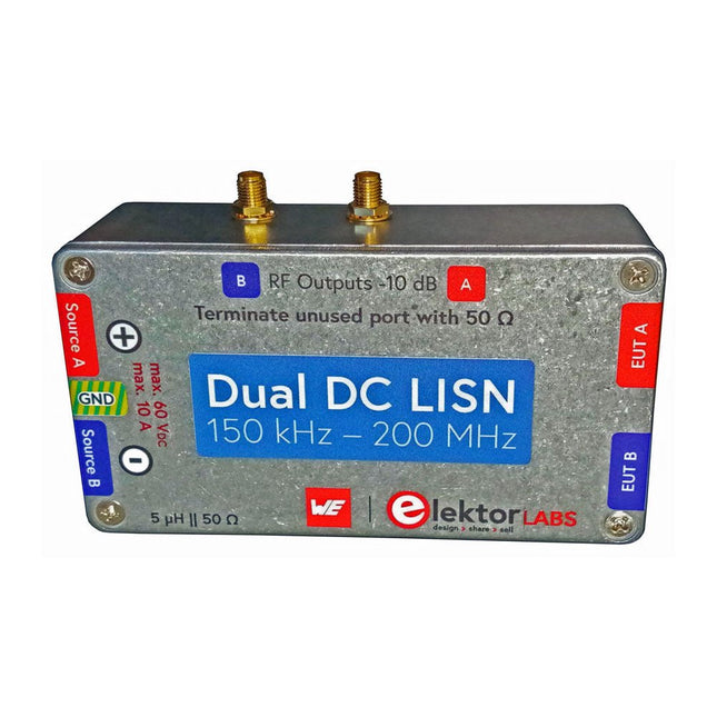
Het meten van conducted emission is de eenvoudigste en meest betaalbare methode om een indicatie te krijgen of een ontwerp aan de EMI/EMC eisen kan voldoen. Een Line Impedance Stabilization Network (LISN) is daarbij een onmisbaar onderdeel van een EMC pre-compliance testopstelling.
Elektor heeft in samenwerking met Würth Elektronik een 5 µH, 50 Ω Dual DC LISN ontwikkeld die geschikt is voor spanningen tot 60 V en stromen tot 10 A.
Het instrument meet RF-interferenties op beide kanalen (de voeding) door middel van 5 µH blokkeerspoelen. De interne 10 dB verzwakkingstrap – één per kanaal – bevat een 3e orde hoogdoorlaatfilter met een afsnijfrequentie van 9 kHz om de ingang van instrumenten zoals een spectrum analyzer te beschermen tegen mogelijk schadelijke DC spanningen of lage frequenties afkomstig van de DUT (Device Under Test).
Specificaties
RF-pad
Kanalen
2 (met clamping diodes)
Bandbreedte
150 kHz – 200 MHz
Impedantie
5 µH || 50 Ω
Interne demping
10 dB
Connectoren
SMA
DC-pad
Max. stroom
< 10 ADC
Max. spanning
< 60 VDC
DC weerstand
< 2 x 70 mΩ
PCB-formaat
94,2 x 57,4 mm
Connectoren
4 mm banaan
Hammond-behuizing
Type
1590N
Afmetingen
121 x 66 x 40 mm
Inbegrepen
1x 4-laags PCB met alle SMT-onderdelen gemonteerd
1x Voorgeboorde behuizing met bedrukt frontpaneel
5x Vergulde, geïsoleerde 4 mm banaanstekers, geschikt voor 24 A, 1 kV
1x Hammond-behuizing 1590N1, aluminium (gegoten legering)
Meer info
Project op Elektor Labs: Dual DC LISN for EMC pre-compliance testing
Elektor 9-10/2021: EMC Pre-Compliance Test voor uw DC-gevoed project (deel 1)
Elektor 11-12/2021: EMC Pre-Compliance Test voor uw DC-gevoed project (deel 2)
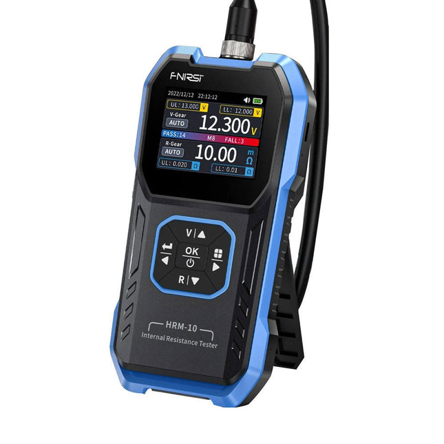
De FNIRSI HRM-10 is een draagbare, zeer nauwkeurige interne weerstands- en spanningstester voor batterijen. Dit apparaat biedt echte vierdraadsmetingen en is ontworpen voor zowel nauwkeurigheid als gebruiksgemak. Het meet automatisch tegelijkertijd de interne weerstands- en spanningswaarden en geeft de resultaten op het HD-kleurenscherm weer. Gebruikers hebben de mogelijkheid om het spannings- en weerstandsbereik handmatig aan te passen aan hun behoeften. Het apparaat bevat ook een sorteermodus die automatisch de goede en slechte batterijen filtert op basis van door de gebruiker ingestelde drempels. Bovendien ondersteunt het de opslag van historische gegevens en is het mogelijk meetgegevens in tabelformaat te exporteren.
Kenmerken
Hoge meetnauwkeurigheid
Tabelgegevens exporteren
Meetresultaten automatisch evalueren
8 drempelinstellingen
HD-kleurenscherm
Opvouwbare standaard
1000 mAh lithiumbatterij
Specificaties
Spanning
Weerstand
Meetbereik
0-100 V (DC)
0-200 Ω
Nauwkeurigheid
±0,5%
±0,5%
Uitrusting
Automatisch, 1 V, 10 V, 100 V
Automatisch, 20 mΩ, 200 mΩ, 2 Ω, 20 Ω, 200 Ω
Instrumenttestsignaalfrequentie
1 Khz (AC)
Oplaadbaar
USB-C (5 V/1 A)
Ingebouwde batterij
1000 mAh lithiumbatterij
Gebruikerskalibratie
Ja
Sorteermodus
Ja
Geschiedenisrecord
Ja
Export van opgenomen gegevens
Ja
Werkomgeving
–10°C tot +45°C, relatieve vochtigheid <80%
Opslagomgeving
–20°C tot +80°C, relatieve vochtigheid <80%
Afmetingen
158,7 x 80,5 x 28,4 mm
Gewicht
225 g
Inbegrepen
1x FNIRSI HRM-10 interne weerstandstester
1x Clip-testlijn
1x USB-C datakabel
1x Manual
Downloads
Manual
Firmware V0.3
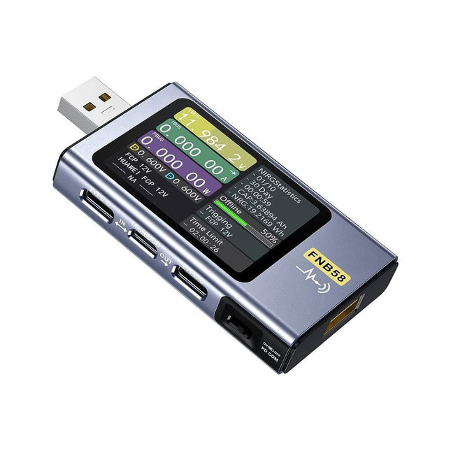
De FNB58 USB-tester (met Bluetooth) is een uitgebreide en zeer nauwkeurige USB spannings- en stroommeter. Hij beschikt over een 2,0" full-color HD TFT-display, ingebouwde USB-A, micro-USB en USB-C interface. Met dit apparaat kunt u de voeding of het stroomverbruik van producten meten, of het laadvermogen van mobiele telefoons en voedingen bepalen. Ook kunt u het snellaad protocol van laders in kaart brengen.
Kenmerken
USB-A en USB-C interface
2,0 inch HD-display
Alle gegevens in één oogopslag
Brede compatibiliteit
Ultra nauwkeurige gegevensdetectie
Speel met snellaad technologie
Automatische protocol detectie (PD2.0, 3.0, 3.1, PPS, QC2.0, 3.0, FCP, SCP, AFC, PE, DASH VOOC, SuperVOOC en meer)
Eenvoudige gebruikersinterface, eenvoudig te bedienen
4 functiecurve weergaves (real-time spannings- en stroomcurve, offline curve-opname, D+/D- spanningscurve, snelle meting van de rimpelspanning van de voeding)
Kabeldetectie
10 groepen berekeningen van de accucapaciteit energieopslag
Op PC aan te sluiten voor datalogging en firmware-updates
Bluetooth-app voor Android-apparaten
Specificaties
Spanningsbereik
4-28 V
Stroombereik
0-7 A
Vermogensbereik
0-120 W
Equivalente waardes interne weerstand bij belasting
0-9999,9 ?
D+/D- spanning
0-3,3 V
Capaciteit
0-9999,99 Ah
Stroomverbruik
0-9999,99 Wh
Kabel weerstand
0-9999,9 ?
Interfaces
micro-USB, USB-A, USB-C
Afmetingen
42 x 13 x 82 mm
Downloads
Manual
Firmware V0.68
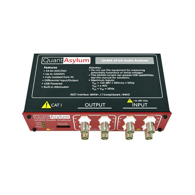
De QA403 is de vierde generatie audio analyzer van QuantAsylum. Deze QA403 verhoogt de functionaliteit van de QA402 met verbeterde ruis- en vervormingsprestaties, en ook een vlakkere respons aan de randen van de band. Het compacte formaat van de QA403 zorgt ervoor dat u hem vrijwel overal mee naartoe kunt nemen.
Kenmerken
24-bits ADC/DAC
Tot 192 kS/s
Volledig geïsoleerd van de PC
Differentiële input/output
USB gevoed
Ingebouwde demping
Snel opstarten en geen stuurprogramma
De QA403 is een USB-apparaat zonder stuurprogramma's, wat betekent dat hij meteen operationeel is zodra u hem aansluit. De software is gratis, en u kunt snel en gemakkelijk de hardware van de ene machine naar de andere verplaatsen. Dus als u naar een vestiging moet om een probleem op te lossen, of de QA403 mee naar huis dient te nemen op een thuiswerkdag, dan kunt u dit zonder veel gedoe doen.
No-Cal ontwerp
De QA403 wordt geleverd met een fabriekskalibratie in het flashgeheugen, waardoor consistente prestaties bij gebruik van meerdere analyzers kan worden gegarandeerd. Op uw productielijn kunt u een andere QA403 installeren en erop vertrouwen dat wat u op de ene analyzer leest overeenkomt met de andere. Er hoeft dus niet geregeld herkalibratie plaats te vinden.
Metingen
Het uitvoeren van basismetingen kan snel en eenvoudig. In een paar klikken krijgt u inzicht in de frequentierespons, de THD (+ N), de versterking, de SNR, en andere gegevens van uw geteste apparaat.
Dynamisch bereik
De QA403 biedt 8 gradaties aan versterking op de ingang (0 tot +42 dBV in 6 stappen) en 4 stappen versterking op de uitgang (-12 tot +18 dBV in stappen van 10 dB). Dit zorgt voor consistente prestaties over zeer brede in- en uitgangsniveaus. De maximale AC ingangsspanning op de QA403 is +32 dBV = 40 Vrms. De maximale DC is ±40 V en de maximale ACPEAK + DC = ±56 V.
Eenvoudig te programmeren
De QA403 ondersteunt een REST-interface, waardoor het eenvoudig is om metingen te automatiseren in vrijwel elke taal. Van Python tot C++ tot Visual Basic: als u weet hoe u een webpagina in uw favoriete taal moet laden dan kunt u al de QA403 op afstand bedienen. Metingen zijn snel en responsief, doorgaans met het verwerken van tientallen opdrachten per seconde.
Geïsoleerd, en gevoed via USB
De QA403 werkt geïsoleerd van de pc, wat betekent dat u echt uw te testen apparaat meet, en niet met een fantoom aardlus te doen heeft. De QA403 wordt gevoed via USB, zoals bijna alle QuantAsylum instrumenten. Indien u op afstand moet configureren, neem dan een hub met voeding mee in uw tas en uw hele testopstelling kan dan functioneren met een minimum aan kabels.
Vaarwel geluidskaart, hallo QA403
Moe van het proberen om een geluidskaart aan de praat te krijgen? Nachtmerries van het kalibreren? Gemis van de juiste versterking? Of te weinig aansturing? Bent u het zat om met vaste ingangsranges om te gaan? Of bang dat u zaken kapot maakt met te veel DC of AC? Moe van de aardlussen? Dáarom heeft QuantAsylum de QA403 ontworpen.
Specificaties
Afmetingen
177 x 44 x 97 mm (B x H x D)
Gewicht
435 g
Case Materiaal
Aluminium met poedercoating (2 mm dik voorpaneel, 1.6 mm dikke boven/onderkant)
Downloads
Datasheet
Manual
GitHub
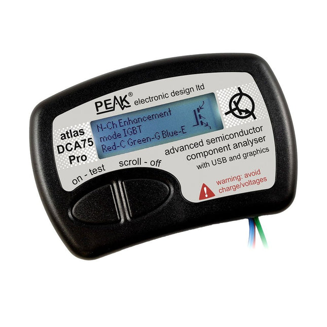
The DCA75 Pro is a great instrument that combines ease-of-use with amazing features. It can automatically identify a huge range of semiconductors, automatically identify pinouts and measure detailed parameters.
Kenmerken
Built-in graphics display (now backlit) to show detailed schematic of the component you're testing as well as pinout and measurement data.
USB connectivity to allow curve tracing, data storage/retrieval and device matching on your Windows PC (Windows 7 and higher).
Single internal AAA alkaline cell for standalone operation.
Component Support
Bipolar transistors (NPN/PNP inc Silicon/Germanium)
Darlington transistors (NPN/PNP)
Enhancement mode MOSFETs (N-Ch and P-Ch)
Depletion mode MOSFETs (N-Ch and P-Ch)
Junction FETs (N-Ch and P-Ch). Both symmetrical and asymmetrical types
Enhancement IGBTs (N-Ch and P-Ch)
Diodes and diode networks (2 and 3 lead types)
Zener diodes (up to about 9 V)
Voltage regulators (up to about 8 V)
LEDs and bi-colour LEDs (2 lead and 3 lead types)
Low power sensitive Triacs and Thyristors (<10 mA trigger and hold)
Measurements
BJT current gain (hFE)
BJT base emitter voltage (Vbe)
BJT collector leakage current
MOSFET on and off gate threshold voltages
MOSFET transconductance
JFET pinch-off voltage
JFET transconductance
JFET IDSS (drain current for Vgs=0)
IGBT on and off gate threshold voltages
IGBT transconductance
Voltage regulator output voltage
Voltage regulator quiescent current consumption
Voltage regulator drop-out voltage
Zener voltage
Diode forward voltage drop
Specificaties
Analyzer type
Semiconductor components
Component detection
Automatic
Pinout detection
Automatic, connect any way round
Display type
Graphic LCD (now backlit)
Interface type
USB for optional PC connection
PC functions
Curve tracing (Windows 7 and higher)
Software
Included on USB drive for Windows 7 and higher
Battery
Single AAA cell (supplied)
Inbegrepen
Peak Atlas DCA75 Pro
PC software on a USB Flash Drive for Windows 11, 10, 8, 7, XP
Micro USB cable
Fitted universal premium hook probes
AAA Alkaline battery
Downloads
Datasheet (EN)
User Guide (EN)
Software Installation Guide (EN)
Software and Firmware Package
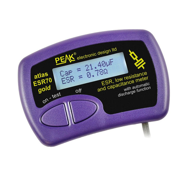
The Peak Atlas ESR70 gold is an enhanced version of the previous Peak Atlas ESR70 Plus. It does everything that the ESR70 Plus did but better.
It now measures capacitance up to 10x faster, and over a wider range, thanks to new test algorithms. The capacitance measurement is also much less influenced by parallel resistances or leakage current thanks to our new Triple-Slope measurement system.
Using the supplied gold plated probes (removable), the Atlas ESR70 gold can measure ESR down to a resolution of 0.01 ohms, up to 40 ohms. It can even measure ESR for capacitors that are in-circuit. Probes are removable, allowing 2 mm compatible probes to be fitted. Audible alerts are produced for various ESR levels allowing you to perform many tests in succession without having to look at the display. The ESR70 automatically takes capacitive reactance into account, so even low value capacitors (down to 0.3 uF) can have the ESR measured accurately.
Kenmerken
Uses a single AAA Alkaline cell (included).
Alphanumeric LCD with backlight.
Automatic analysis-start when you apply the probes.
Automatic capacitor discharge using controlled discharge function.
ESR (and low DC resistance) measurement (even in-circuit).
Capacitive reactance automatically taken into account to ensure accurate ESR.
Capacitance measurement (if testing out-of-circuit).
Audible alerts for various ESR levels.
Extended ESR measurement range up to 40 Ohms.
Optional probe alternatives easily fitted.
New gold Features
Improved LCD with better backlight.
10x faster capacitance measurement for large capacitors.
Enhanced user options system.
New triple-slope measurement system to vastly reduce the influence of parallel resistance and/or leakage current on capacitance measurements.
Much wider capacitance measurement range now 0.3 uF to 90,000 uF (was 1uF to 22,000uF).
Specificaties
Analyzer type
ESR and Capacitance
Component types
Capacitors (>0.3 uF)
ESR range
0.00 Ohms to 40.0 Ohms
ESR resolution
From 0.01 Ohms
In-circuit use
ESR only
Capacitance range
0.3 uF to 90000 uF
Battery type
1.5 V Alkaline AAA Cell (supplied). Life typically 1500 ops
Display type
Alphanumeric LCD (with backlight)
Inbegrepen
Peak Atlas ESR70 gold
Extra-long and extra-flexible test cables (450 mm of Silicone covered cable)
2 mm gold plated plugs and sockets with removeable gold plated crocodile clips
Comprehensive illustrated user guide
AAA Alkaline cell
Downloads
Datasheet (EN)
User Guide (EN)
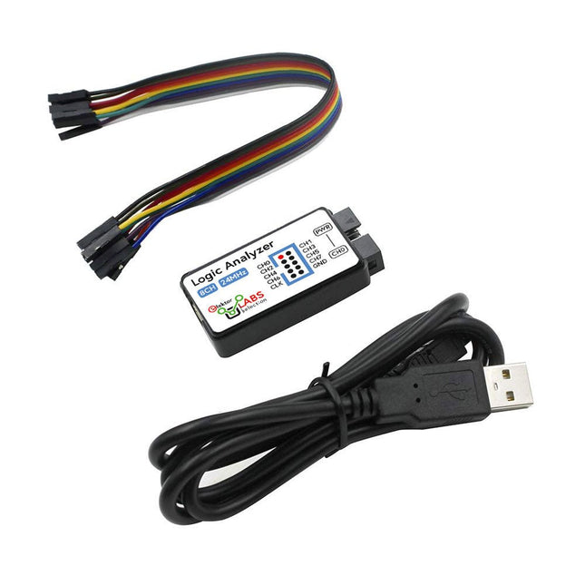
Deze USB Logic Analyzer is een 8-kanaals logic analyzer met elke ingang bedoeld voor het op twee manieren opnemen van analoge data. Hij is perfect voor het debuggen en analyseren van signalen zoals I²C, UART, SPI, CAN en 1-Wire. De analyzer bemonstert een digitale ingang die is aangesloten op een te testen apparaat (DUT) met een hoge bemonsteringssnelheid. De aansluiting op de PC gaat via USB.Specificaties
Kanalen
8 digitale kanalen
Maximale bemonsteringssnelheid
24 MHz
Maximale ingangsspanning
0 V ~ 5 V
Bedrijfstemperatuur
0°C ~ 70°C
Ingangsimpedantie
1 MΩ || 10 pF
Ondersteunde protocollen
I²C, SPI, UART, CAN, 1-wire, enz.
PC-aansluiting
USB
Afmetingen
55 x 28 x 14 mm
Inbegrepen
USB Logic Analyzer (8-kanaals, 24 MHz)
USB-kabel
Jumper Draad Lintkabel
DownloadsSoftware
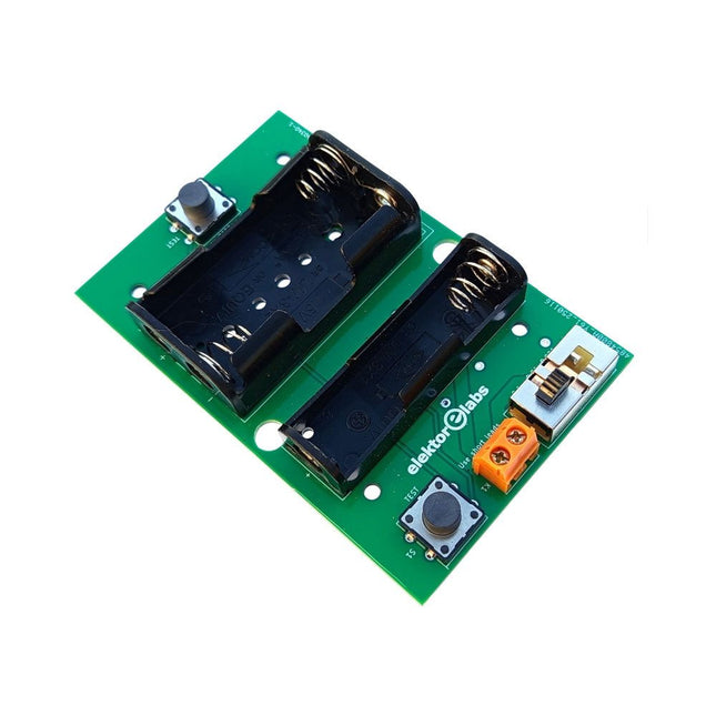
De Elektor Milliohmmeter Adapter gebruikt de precisie van een multimeter om zeer lage weerstandswaarden te meten. Het is een adapter die een weerstand omzet in een spanning die kan worden gemeten met een standaard multimeter.
De Elektor Milliohmmeter Adapter kan weerstanden meten onder 1 mΩ met behulp van een 4-draads (Kelvin) methode. Het is handig voor het lokaliseren van kortsluitingen op printplaten (PCB).
De adapter heeft drie meetbereiken – 1 mΩ, 10 mΩ en 100 mΩ – selecteerbaar via een schuifschakelaar. Het bevat ook ingebouwde kalibratieweerstanden. De Elektor Milliohmmeter Adapter wordt gevoed door drie 1,5 V AA batterijen (niet meegeleverd).
Specificaties
Meetbereiken
1 mΩ, 10 mΩ, 100 mΩ, 0,1%
Voeding
3x 1,5 V AA-batterijen (niet inbegrepen)
Afmetingen
103 x 66 x 18 mm (compatibel met Hammond 1593N-type behuizing, niet inbegrepen)
Speciale functie
Geïntegreerde kalibratieweerstanden
Downloads
Documentation
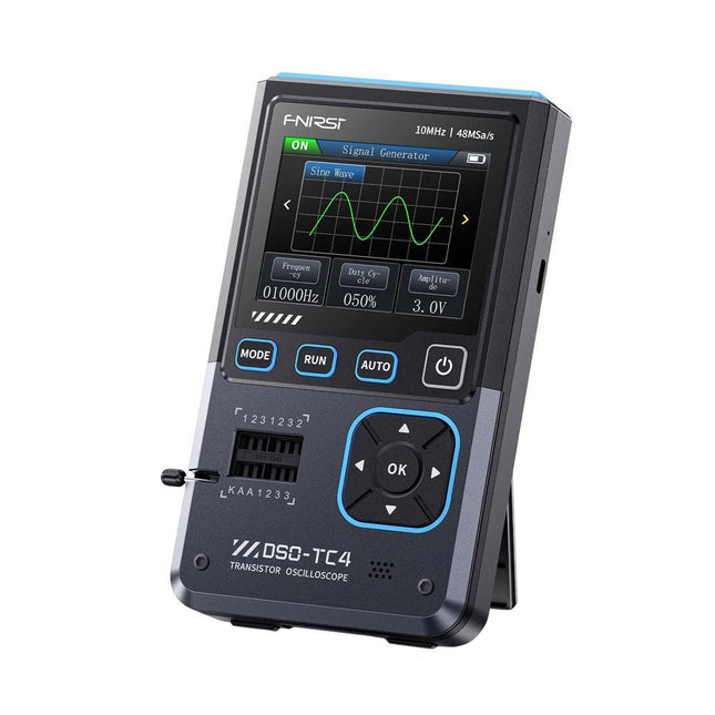
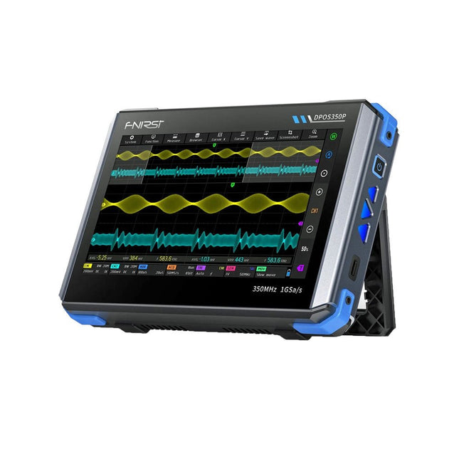
2 kanalen • 350 MHz • 1 GSa/s • 50.000 wfm/s • 7 inch Touchscreen
De FNIRSI DPOS350P is een gestroomlijnde 4-in-1 krachtpatser in tabletvorm! Dit compacte en draagbare apparaat biedt serieuze functionaliteit: het combineert een 2-kanaals oscilloscoop (350 MHz), een signaalgenerator (50 MHz), een frequentieresponsanalyzer (50 MHz) en een spectrumanalyzer (200 kHz–350 MHz) – alles in één apparaat.
Of u nu bezig bent met R&D, probleemoplossing of veldtesten, de DPOS350P biedt de tools die u nodig hebt om elektronische signalen nauwkeurig en helder te meten, genereren, analyseren en visualiseren. Het responsieve touchscreen met hoge resolutie en de intuïtieve bediening maken signaalanalyse snel, flexibel en efficiënt.
Kenmerken
Krachtige multifunctionele integratie
350 MHz 2-kanaals oscilloscoop met 1 GSa/s realtime sampling
50 MHz signaalgenerator met 14 standaard + aangepaste golfvormen
Spectrum analyzer (200 kHz–350 MHz): Perfect voor EMI, RF en HF-testen
Frequentieresponsanalyzer (FRA) tot 50 MHz
Hoogwaardige golfvormregistratie
Vernieuwingsfrequentie van 50.000 wfm/s voor realtime signaalhelderheid
Bandbreedte van 350 MHz (enkelkanaalsmodus)
Detecteert zeldzame en onwaarschijnlijke afwijkingen
Scherp display & Soepele werking
7" IPS-touchscreen (resolutie 1024 x 600)
Schakelen tussen grijstinten- en kleurtemperatuurweergave
Eenvoudig te bedienen in verschillende testomgevingen
Betrouwbaar, beveiligd en snel opladen
Hoogspanningsbeveiliging tot 400 V
Snel opladen met QC 18 W (volledig opladen in 2 uur)
Gebouwd voor stabiele, langdurige werking
Gegevensopslag en -export
Sla tot 500 golfvormrecords + 90 screenshots op
USB-export voor eenvoudige rapportage en offline analyse
Specificaties
Algemeen
Scherm
7 inch (IPS, volledige kijkhoek)
Resolutie
1024 x 600 pixels
Interactiemodus
Capacitief touchscreen
Totaal stroomverbruik
10 W
Inschakelconfiguratie
5 voorinstellingen
Opladen
QC 18 W, 12 V/1,5 A (USB-C)
Accu
3,7 V, 8000 mAh lithiumbatterij
Accuduur
ca. 3 uur in gebruik, 5 uur stand-by
Warmteafvoer
Luchtkoeling
Uitbreidingsinterface
USB-poort
Automatische uitschakeling
15 tot 60 minuten / uit
Firmware-upgrade
Ondersteunt .iso-image-upgrade
Talen
Engels / Portugees / Russisch / Chinees
Afmetingen
190 x 128 x 37 mm
Oscilloscoop
Analoge kanalen
2
Analoge bandbreedte
350 MHz
Stijgtijd
1 ns
Real-time bemonsteringsfrequentie
1 GSa/s
Geheugendiepte
60 Kpts
Ingangsimpedantie
1 MΩ / 14PF
Tijdbasisbereik
5 ns ~ 50 s
Roltijdbasis
50 ms ~ 50 s
Verticale gevoeligheid
2 mV ~ 20 V (1X)
Verticaal bereik
16 mV ~ 160 V (1X)
DC-nauwkeurigheid
±2%
Tijd nauwkeurigheid
±0,01%
Ingangskoppeling
DC / AC
Probe-verzwakking
1X / 10X / 100X
Hardwarebandbreedtelimiet
150M / 20M
Hoge-resolutiemodus
8 bit ~ 16 bit
Parametermetingen
12 typen
Cursormeting
Tijd, periode, frequentie, niveau, spanning
Triggerdetectie
Digitale trigger
Triggerkanaal
CH1 / CH2
Triggermodus
Auto / Single / Normal
Triggerflank
Rising edge / Falling edge
Triggeronderdrukking
L1 ~ L3
Triggerniveau
Handmatig / automatisch 10% ~ 90%
Screenshot-opslag
90 afbeeldingen
Golfvormopslag
500 groepen
Achtergrondraster
Weergeven/verbergen
Golfvormbeweging
Grof/fijn afstellen
Overspanningsbeveiliging
Bestandsspanning 400 V
Helderheid golfvorm
Instelbaar
Eenvoudig FFT-display
Ja
Digitale fluorescentie
Ja
Kleurtemperatuurweergave
Ja
X-Y-modus
Ja
ZOOM-tijdbasis
Ja
Automatische aanpassing met één druk op de knop
Ja
Terug naar nul met één druk op de knop
Ja
Gegevensbrowser
Ja
Signaalgenerator
Golfvormtypen
14 standaardfuncties + vastgelegde golfvorm
Frequentie
0~50 MHz (alleen sinusgolf, andere golfvormen tot 10M/5M/3M)
Amplitude
0~5 VPP
Offset
-2,5 V ~ +2,5 V
Bedrijfstype cyclus
0,1~99,9%
Frequentieresolutie
1 Hz
Amplituderesolutie
1 mV
Offsetresolutie
1 mV
Inschakelduurresolutie
0,1%
Aanpasbare vastgelegde golfvorm
500 groepen
Frequentieresponsanalyzer (FRA)
Frequentie van het excitatiesignaal
100 Hz ~ 50 MHz
Ampitude van het excitatiesignaal
0~5 VPP
Offset van het excitatiesignaal
-2,5 V ~ +2,5 V
Aantal excitatiefrequenties
20~500
Cursormeting
Frequentie / versterking / fase
Bedrijfsmodus
Enkelvoudig / cyclisch
Systeemkalibratie
Ja
Spectrumanalyzer
Conversiemethode
FFT
FFT-lengte
4K ~ 32K
Frequentiebereik
200 kHz ~ 350 MHz
Niveaubereik
-60 dBmV ~ +260 dBmV
Cursormeting
Frequentie / amplitude
Markeringsparameter
Maximale energieharmonischen
Watervalgrafiek
Ja
3D-watervalgrafiek
Ja
Automatische afstelling
Ja
Systeemkalibratie
Ja
Inbegrepen
1x FNIRSI DPOS350P (4-in-1)
2x 350 MHz-sondes
1x QC 18 W snellader (EU)
1x USB-datakabel
1x Krokodillenklem
1x Opbergtas
1x Manual
Downloads
Manual
Firmware
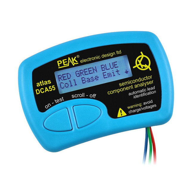
The Peak Atlas DCA55 is great for automatically identifying the type of semiconductor on the test leads as well as the pinout and many other parameters.
Supports transistors MOSFETs, JFETs (gate pin only can be identified), diodes, LEDs and lots more. Automatically identifies type of component, pinout and other important parameters. Now features transistor leakage measurement and Germanium/Silicon identification.
Component Support
Bipolar transistors (NPN/PNP inc Silicon/Germanium)
Darlington transistors (NPN/PNP)
Enhancement mode MOSFETs (N-Ch and P-Ch)
Depletion mode MOSFETs (N-Ch and P-Ch)
Junction FETs (N-Ch and P-Ch). Only gate lead identified.
Diodes and diode networks (2 and 3 lead types).
LEDs and bi-colour LEDs (2 lead and 3 lead types).
Low power sensitive Triacs and Thyristors (<5 mA trigger and hold)
Measurements
Part type identification
Pinout identification
BJT current gain (hFE)
BJT base emitter voltage (Vbe)
BJT collector leakage current
MOSFET gate threshold voltage
Diode forward voltage drop (Vf)
Specificaties
Analyzer type
Transistors, Diodes, LEDs, MOSFETs, JFETs
Pinout detection
Full pinout (only Gate on JFETs)
Pinout configuration
Connect any way round
Transistor measurements
Vbe, hFE, Iceo
MOSFET measurements
Vgs(on)
Diode measurements
Vf
Probe type
Universal grabber type
Battery
Single AAA cell (supplied). Life typically 1300 ops
Test conditions
Typically 5 mA, 5 V peak
Display type
Alphanumeric LCD (with backlight)
Inbegrepen
DCA55 Semiconductor Component Analyser instrument
Comprehensive illustrated user guide
Fitted universal hook probes
AAA Alkaline battery
Downloads
Datasheet (EN)
User Guide (EN)
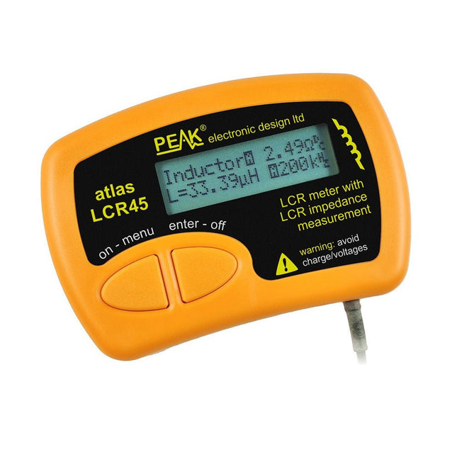
The LCR45 does everything that the popular LCR40 does, but it has some significant enhancements. The LCR45 features a new high capacity micro and high resolution ADCs.
LCR45 incorporates advanced maths, based on Complex Impedance analysis. This allows for enhanced component value measurement as well as a comprehensive and detailed impedance display.
Kenmerken
Supplied with gold plated removable hook probes.
Fluid measurements with hold function.
Automatic or manual component type.
Automatic or manual test frequency, DC, 1 kHz, 15 kHz or 200 kHz.
Enhanced measurement resolution: 0.2 µH, 0.2 pF and 0.2 Ohms.
Easy menu system for user settings.
Enhanced compensation for component parasitics and losses (such as core losses etc).
Automatic or manual power-off.
Specificaties
Analyser type
LCR and component impedance
Component types
Auto/Manual for L,C & R
Measurement types
Inductance, Capacitance and Resistance
Other measurements
Complex impedance/admittance
More measurements
Magnitude and Phase of impedance
Inductance range
0uH to 2H
Capacitance range
0 pF to 10000 uF
Resistance range
0R to 2MR
Test frequency
Auto and manual: DC, 1 kHz, 15 kHz, 200 kHz
Display type
Alphanumeric LCD (not backlit)
Measurement scheme
Continuous (with optional hold)
Battery
GP23 (12 V/55 mAH type), ~700 ops
Inbegrepen
LCR45 Passive Component Impedance Meter
2 mm plugs and sockets and removeable hook probes
Comprehensive illustrated user guide
2 Batteries, one installed and one spare. GP23 Alkaline battery. (12 V/55 mAH)
Downloads
Datasheet (EN)
User Guide (EN)
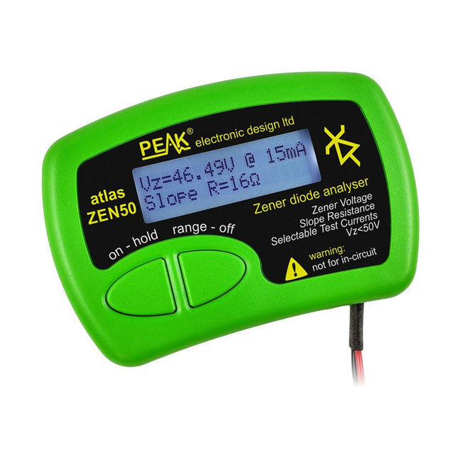
The Peak Atlas ZEN50 is ideal for testing Zener diodes (including avalanche diodes), transient suppressors, LEDs and LED strings. It generates constant current pulses (selectable from 2 mA, 5 mA, 10 mA and 15 mA) at voltages from 0V to 50V. So even high voltage Zeners or high voltage LED strings can be tested.
Test currents are supplied in narrow pulses to ensure that the component under test remains at a constant temperature.
The voltage of the part is displayed on the screen together with the test current and also a measure of the component's slope resistance (also known as dynamic impedance).
Specificaties
Analyzer type
Zeners, LEDs, TVS etc
Test currents
2 mA, 5 mA, 10 mA, 15 mA
Voltage range
0.00 to 50.00 V
Slope resistance range
0 to 8000 Ohms
Battery type
Single AAA (supplied). Life typically 1400 ops
Test method
Triple pulse burst @ 10pps (typ)
Test current duty cycle
3%
Display type
Alphanumeric LCD (with backlight)
Inbegrepen
Peak Atlas ZEN50 Zener Diode Analyzer
Fitted flexible test leads with gold plated crocs
Comprehensive illustrated user guide
AAA Alkaline battery
Downloads
Datasheet (EN)
User Guide (EN)
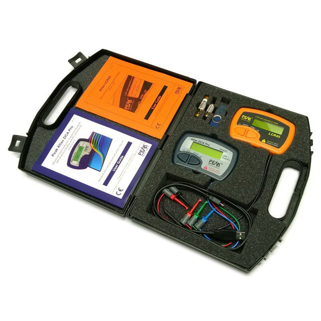
This pack contains the LCR45 Passive Component Impedance Meter, great for advanced hobbyists and professionals. It also contains the very popular DCA Pro (model DCA75), fantastic for component identification, pinout identification, detailed characteristic measurement and curve tracing on a PC. Complete with USB cable and software on a USB flash drive.
DCA75
Building on the continued success of Peak's existing component identification and analysis instruments, the DCA Pro brings an array of exciting new features for the hobbyist and professional alike.
The DCA Pro is an advanced new design that features a graphics display, USB communications, PC Software and an enhanced component identification library.
Automatic component type identification
Automatic pinout identification (connect any way round)
The DCA Pro supports all the components that the popular Peak Atlas DCA55 supports, but adds plenty more. Components supported include:
Transistors (including Darlingtons), Silicon and Germanium types. Measures gain, Vbe and leakage
MOSFETs, enhancement mode and depletion mode types. Measure on-threshold (at 5 mA) and approx transconductance (for span of 3-5 mA)
JFETs, including normally off SiC types. Measures pinch-off voltage (at 1 uA) and approx transconductance (for span of 3-5 mA)
IGBTs (insulated gate bipolar transistors). Measures on-threshold (at 5 mA)
Diodes and Diode networks
LEDs and bicolour LEDs (2 lead and 3 lead types)
Zener Diodes with measurement of zener voltage up to 9 V at 5 mA
Voltage regulators (measures regulation voltage, drop-out voltage, quiescent current)
Triacs and Thyristors that require less than 10 mA of gate current and holding current
Stand-alone or with a PC
The instrument can be used stand-alone or connected to a PC. Either way, the DCA Pro will automatically identify the component type, identify the pinout and also measure a range of component parameters such as transistor gain, leakage, MOSFET and IGBT threshold voltages, pn characteristics and much more.
Curve Tracing
When connected to a PC using the supplied USB cable, a range of low current curve-tracing functions can be performed. Various graph types are available, with more to follow:
Bipolar transistor output characteristics, IC vs VCE
Bipolar transistor gain characteristics, HFE vs VCE
Bipolar transistor gain characteristics, HFE vs IC
MOSFET and IGBT output function, ID vs VDS
MOSFET and IGBT transfer function, ID vs VGS
JFET output function, ID vs VDS
JFET transfer function, ID vs VGS
Voltage regulator, VOUT vs VIN
Voltage regulator, IQ vs VIN.
PN junction I/V curves, forward and reverse options (for Zener diodes)
Curve tracing is performed using test parameters in the range of +/-12 V or +/-12 mA. All curve-tracing data can be instantly pasted into Excel for further graphing and analysis. PC Software is included with the DCA Pro on a Peak USB memory stick. Software designed for Windows 7 and higher (all 32 or 64 bit).
LCR45
A great handheld LCR analyser that can measure the value of your passive component (inductor, capacitor or resistor) and also measure the detailed impedance in a number of modes. The LCR45 offers enhanced measurement resolution (better than 0.1 uH!) whilst also giving you continuous fluid measurements. Additionally, the test frequencies of DC, 1 kHz, 15 kHz and 200 kHz can be set to automatic or manual modes. Supplied with removable gold plated hook probes, battery and user guide. Compatible with standard 2 mm test connectors. Not designed for in-circuit use.
Automatic or manual component type selection: Inductor, Capacitor or Resistor
Automatic or manual test frequency selection: DC, 1 kHz, 15 kHz and 200 kHz
Inductance from 0.1 uH to 10 H
Capacitance from 0.1 pF to 10,000 uF
Resistance from 0.1 Ohm to 2 MOhm
Inductance measurement also shows DC winding resistance
Display of "Component type and values", "Complex Impedance", "Magnitude/Phase" and "Admittance"
Test frequency displayed for all measurements
Typical accuracy of 1.5% for inductors and capacitors (see spec table for details)
Typical accuracy of 1% for resistors
Test lead complete with gold plated 2 mm plugs and sockets
Supplied with removable gold plated hook probes
Inbegrepen
LCR45
DCA75
Extra GP23 Battery
Extra AAA cell
Dual Carry Case
Deze zeer gevoelige picoammeter is ontworpen voor het meten en loggen van zeer kleine stromen tot in het pA-bereik – waardoor het een ideaal instrument is voor wetenschappelijke en onderzoekstoepassingen, waaronder natuurkunde, materiaalkunde en elektronenmicroscopie.
De SPA100, met alle functies voor een betaalbare prijs, combineert gevoeligheid, nauwkeurigheid en stabiliteit om gebruikers in staat te stellen lage stromen met hoge precisie te meten en gemakkelijk biaspanningen voor experimenten te genereren. De SPA100 is ook te gebruiken als ultrahoge weerstandsmeter, die tot in het teraohm-bereik nauwkeurig meet.
De SPA100 wordt via USB aangesloten op een PC en maakt gebruik van de gratis software SPA, waarmee gebruikers eenvoudig metingen kunnen meten, grafieken kunnen maken en meetwaarden met tijdstempels en informatie over meetstabiliteit kunnen vastleggen.
Specificaties
Ingang: ±2 mA tot ±200 pA in 8 bereiken
Nauwkeurigheid en resolutie (2 Hz):
±2 mA bereik: ±0,1%, resolutie <20 nA
±200 uA bereik: ±0,1%, resolutie <2 nA
±20 uA bereik: ±0,2%, resolutie <200 pA
±2 uA bereik: ±0,2%, resolutie <20 pA
±200 nA bereik: ±0,5%, resolutie <2 pA
±20 nA bereik: ±0,5%, resolutie <200 fA
±2 nA bereik: ±1,0%, resolutie <20 fA
±200 pA bereik: ±1,5%, resolutie <2 fA
Bemonsteringssnelheid: 2 Hz (18 bit) of 10 Hz (16 bit)
Verstelbaar filter: 1 Sample tot 64 Samples
Uitgangsspanning: -40 V tot +40 V (in stappen van 1 V), uitgangsweerstand 2,7 Kohm
Weerstandsmeting: ~1 Kohm tot 40 Tohm (bijv. 40 V bron, 1 pA meting)
Nauwkeurigheid: >±0,5% 1 Mohm tot 1 Tohm
Gevoed via USB 2.0 (instrument verbruikt tot 0,3 A tijdens gebruik)
Inbegrepen
1x SPA100 Source Picoammeter
1x USB-kabel
Downloads
Manual
Software
Features
Internal LNA amplifier and selectable attenuator
Low frequency support from 50KHz covering LF, MF, HF, VHF and UHF up to 960Mhz
New HELP and SET buttons to improve user interface and configuration selection with 2-clicks
Wide band coverage to all popular sub-1Ghz bands, including FM, TV and DTV, ISM, RFID, GSM, etc.
Ideal choice for HAM bands from 160meters to 33cm
Pocket size and light weight
Solid metal case
Spectrum Analyzer mode with Peak Max and Hold, Normal, Overwrite and Averaging modes
High capacity internal Lithium battery for 20hs+ of continuous run, rechargeable by USB
Multi-platform Windows/Linux/MacOS Open Source software and API libraries
Can be extended with internal Expansion Modules for additional band and functionality
Specifications
Frequency band: 0.05 MHz - 960 MHz
Frequency span: 0.1 MHz - 960 MHz
Internal selectable LNA 25 dB gain
Internal selectable Attenuator 30 dB
Graphics LCD 128 x 64 pixels, great visibility outdoors
Support included for Windows, Linux and MacOS X
Backlight for great visibility indoor
Internal Lithium Ion 1800mA/h rechargeable battery
Standard SMA 50 Ω connector
Wideband 144/433MHz dual band telescopic antenna included
UHF 400-900 MHz rubber duck articulated antenna included
Amplitude resolution: 0.5dBm
Dynamic range: -125 dBm to 10 dBm
Absolute Max input power: +30dBm
Average noise level (typical LNA): -125 dBm
Frequency stability and accuracy (typical): +-10 ppm
Amplitude stability and accuracy (typical): +-2d Bm
Frequency resolution: 1kHz
Resolution bandwidth (RBW): automatic 2.6 kHz to 600 kHz
Included
1x RF Explorer WSUB1G+ Spectrum Analyzer
1x Mini USB cable
1x Dual band 144/430MHz Telescopic antenna
1x UHF 400-900Mhz antenna
1x EVA case
You can use RF Explorer 3G Combo equally well outdoor and indoor, and you can also connect it to a PC for extra functionality using standard mini-USB 2.0 connector.
This model includes a WSUB1G baseline unit plus an RFEMWSUB3G Expansion Module conveniently assembled and tested. It comes with two SMA connectors and two antennas,a dual band telescopic 144 / 430 MHz antenna for all Sub-GHz frequencies and a whip helical antenna for 2.4 GHz band. Additional, specific band antennas may be needed to cover efficiently some of the frequencies supported.
The combination of these two models offer the wide band coverage of the WSUB3G module, together with the highest sensitivity and quick response of the WSUB1G model for the popular sub-1GHz frequencies.
Features
Pocket size and light weight
Solid aluminum metal case
Includes a transport EVA carry case for RF Explorer
Spectrum Analyzer mode with Peak Max and Hold, Normal, Overwrite and Averaging modes
Lifetime free firmware upgrades available, open to community requested features
High capacity Lipo for 16 hours+ of continuous run, rechargeable by USB
Windows PC client Open Source
Can be extended with internal Expansion Modules for additional band and functionality
Wide band coverage to all popular RF frequencies, starting at 15 MHz and going up to 2.7 GHz. This includes very interesting frequency areas such as 2 m HAM radio, all VHF and UHF, FM radio, GPS, WiFi and WiMax, Bluetooth, etc.
Firmware: RF Explorer 3G Combo is delivered with upgraded firmware v1.09. Note some of the features and operation accuracy will be improved in upcoming free firmware revisions.
Specifications
Battery
Lithium Cells / Batteries contained in equipment UN3481 - PI967
Frequency band
15-2700 MHz
Frequency span
112 KHz - 600 MHz
Graphics LCD
128 x 64 pixels, great visibility outdoors
PC Windows client
supports Windows XP/Vista/Win7 both 32 and 64bits
Backlight
for great indoor visibility
2 standard SMA 50 ohms connector,
one for Sub-GHz wideband Nagoya NA-773 telescopic antenna included and another 2.4 GHz one for 15-2700 MHz band with helical antenna included.
Amplitude resolution
0.5 dBm
Dynamic range
Left SMA port (WSUB1G)
-115 dBm to 0 dBm
Right SMA port (WSUB3G)
-110 dBm to -10 dBm
Absolute Max input power
Left SMA port (WSUB1G)
+5 dBm
Right SMA port (WSUB3G)
+30 dBm
Average noise level (typical)
-110 dBm
Frequency stability and accuracy (typical)
+-10 ppm
Amplitude stability and accuracy (typical)
+-6 dBm
Frequency resolution
1 KHz
Resolution bandwidth (RBW)
automatic 3 KHz to 600 KHz
Weight
185 g
Size
113 x 70 x 25 mm
Included
RF Explorer 3G Combo
Nagoya NA-773 wideband telescopic antenna
2.4 GHz band antenna
EVA Case
Documentation
For more info and to get started with your RF Explorer, visit the start page.
For questions and support, please visit https://support.rf-explorer.com
Deze bundel bevat de Red Pitaya STEMlab 125-14 PRO Gen 2 Starter Kit en het nieuwe boek "Experimenteren met Red Pitaya STEMlab Gen 2".
De Red Pitaya STEMlab 125-14 PRO Gen 2 Starter Kit is een krachtig en flexibel platform voor signaalverwerking, data-acquisitie en elektronische meettoepassingen. Deze kit is ontworpen voor ingenieurs, ontwikkelaars, onderzoekers en docenten en biedt alles wat nodig is om te beginnen met het bouwen van geavanceerde meet- en besturingssystemen.
De kern van de kit wordt gevormd door het STEMlab 125-14 PRO Gen 2-bord, een geüpgradede en ultralichte ontwikkeling. Aangedreven door de Xilinx Zynq-7010 SoC met 512 MB RAM, combineert het de programmeerbaarheid van een FPGA met de verwerkingskracht van een ARM-processor om hoogwaardige instrumentatie en aangepaste signaalverwerkingsoplossingen mogelijk te maken.
Het bord biedt een 14-bits ADC- en DAC-resolutie, een bemonsteringsfrequentie van 125 MS/s, een ingangsbereik van ±20 V en een bandbreedte tot 60 MHz. Dankzij de verbeterde ruisarme analoge front-end, USB-C-connectiviteit en het compacte ontwerp is het geschikt voor veeleisende toepassingen zoals RF-ontwikkeling, radarsystemen, fotonica-onderzoek, softwaregedefinieerde radio (SDR) en industriële automatisering.
De Starter Kit bevat alle essentiële accessoires voor onmiddellijk gebruik: een microSD-kaart met vooraf geïnstalleerd besturingssysteem, voeding, ethernetkabel voor toegang op afstand, twee 100 MHz-oscilloscoopprobes en SMA-naar-BNC-adapters voor flexibele signaalaansluitingen.
De Red Pitaya STEMlab 125-14 PRO Gen 2 Starter Kit is een uitstekend platform voor rapid prototyping, FPGA-ontwikkeling, meetinstrumentatie en geavanceerde elektronica-experimenten.
Kenmerken
14-bits ADC- en DAC-resolutie
125 MS/s samplingfrequentie
±20 V ingangsbereik
Tot 60 MHz bandbreedte
Xilinx Zynq-7010 SoC (FPGA + ARM-processor)
512 MB RAM
Ruisarme analoge front- en back-ends
Toepassingen
RF-ontwikkeling en -testen
Radar- en draadloze systemen
Software Defined Radio (SDR)
Fotonica en optisch onderzoek
Industriële automatisering en besturingssystemen
Signaalanalyse en instrumentatie
Snel prototypen van elektronische meetsystemen
Specificaties
Processor
Dual-core ARM Cortex-A9
FPGA
AMD Xilinx Zynq-7010 SoC
RAM
512 MB (4 Gb)
Opslag
microSD-kaart (tot 32 GB)
Besturingssysteem
Linux-gebaseerd Red Pitaya OS
ADC-resolutie
14-bits
DAC Resolutie
14-bits
Bandbreedte
60 MHz (DC)
Sampling rate
125 MS/s
Analoge ingangskanalen
2
Analoge uitgangskanalen
2
Ingangsspanningsbereik
±1 V (LV) / ±20 V (HV)
Ingangsimpedantie
1 MΩ / 10 pF
Uitgangsspanningsbereik
±1 V
Ethernet
1x Gigabit Ethernet (RJ45)
USB
2x USB-C 2.0 (voor voeding en console)
Digitale I/O
16x GPIO (3,3 V)
Communicatie-interfaces
I²C, SPI, UART, CAN
Voeding
5 V/3 A via USB-C
Afmetingen
106,8 x 60,0 x 17,9 mm
Inbegrepen
1x Red Pitaya STEMlab 125-14 PRO Gen 2 Board
2x 100 MHz oscilloscoopprobes
2x SMA-naar-BNC-adapters
1x microSD-kaart met voorgeïnstalleerd besturingssysteem
1x USB-C-voeding
1x Ethernetkabel
Downloads
Documentation
Schematics
Book: Experimenting with Red Pitaya STEMlab Gen 2
Met dit nieuwe boek gaat Red Pitaya verder dan een veelzijdig board. Het wordt een krachtig laboratoriuminstrument voor nauwkeurige metingen, analyse en besturing.
Van de basisprincipes van elektronische projectontwikkeling, monitoring, besturing en ontwerp tot testen: dit boek begeleidt u stap voor stap door alles wat u moet weten om het volledige potentieel van de Red Pitaya-hardware en -software te benutten.
Het boek presenteert real-time, FPGA-gebaseerde projecten die op een PC worden ontwikkeld met de Vivado-omgeving en vervolgens naar de Red Pitaya worden overgebracht voor uitvoering en testen.
U leert over verbeterde prestaties, uitgebreide I/O-mogelijkheden, verbeterde FPGA-functionaliteiten en geavanceerde connectiviteitsopties die nieuwe mogelijkheden openen voor nauwkeurige metingen, monitoring en besturing in uw embedded toepassingen.
In dit boek ontdekt u:
Een diepgaande verkenning van de Red Pitaya-architectuur en het hardwareontwerp
Elektronische experimenten met Red Pitaya voor meting en monitoring
Praktische projecten met de programmeertaal Python
Praktische richtlijnen voor FPGA-programmering met Red Pitaya
Red Pitaya FPGA-projecten met Verilog HDL in de Vivado IDE
Praktisch ontwerp van elektronische projecten inclusief meting en testen
Stapsgewijze voorbeelden die theorie en praktijk met elkaar verbinden
Of u nu uw eigen elektronische schakelingen ontwerpt, tools voor signaalanalyse ontwikkelt of real-time besturings- of monitoringssystemen creëert, dit boek biedt u de kennis en het vertrouwen om het Red Pitaya-platform volledig te leren kennen en aan te passen.
De FNIRSI GC-03 is een multifunctionele stralingsdetector, ontworpen voor professionele metingen van nucleaire straling in alledaagse omgevingen zoals thuis, op kantoor, in de auto en buitenshuis. Het apparaat is voorzien van een 2,4-inch high-definition kleurendisplay en maakt real-time monitoring mogelijk van zowel nucleaire straling als de sterkte van elektrische en magnetische velden. Voor extra veiligheid beschikt het toestel over drie alarmmodi: een geluidssignaal, trillingen en een visuele lichtwaarschuwing.
Kenmerken
3-in-1 detectie: Meet elektrische, magnetische en nucleaire straling met één enkel apparaat.
Uiterst nauwkeurige GM-buis: Detecteert nauwkeurig gamma-, röntgen- en harde bètastraling bij een laag energieverbruik.
Realtime grafiek + 50 alarmmeldingen: Volgt stralingstrends en slaat de alarmgeschiedenis op voor eenvoudige controle.
Aanpasbare drievoudige alarmen: Ondersteunt visuele, akoestische en trilwaarschuwingen met instelbare drempelwaarden.
Lange batterijduur: 1500 mAh-accu voor langdurig en betrouwbaar gebruik in het veld.
Specificaties
Kernstraling
Bereik: 0,01 μSv/u - 999,99 μSv/u
Nauwkeurigheid: 0,01 μSv/u
Elektrisch veld
Bereik: 1 V/m - 1999 V/m
Nauwkeurigheid: 1 V/m
Magnetisch veld
Bereik: 0,01 μT - 99,99 μT
Nauwkeurigheid: 0,01 μT
Stralingsvermogen
0,2 - 1000 mW/m²
Type gedetecteerde straling
Ioniserende straling (gammastraling, enz.)
Detector
GM-buis met energiecompensatie (Geigertellerbuis)
Dosisdebiet
0,00 - 10000 μSv/u (10 mSv/u)
Cumulatief dosis-equivalent
0,00 μSv - 500,0 mSv
Energiebereik
48 keV - 1,5 MeV ≤ ±30% (voor 137Cs)
Gevoeligheid
80 CPM/μSv
Dosis-eenheid
μSv/u, μGy/u, mR/u, CPS, CPM
Alarmmodus
Licht, trilling, geluid
Display
2,4-inch kleurenscherm
Achtergrondverlichting
Helderheid instelbaar
Voeding
USB-C (5 V/1 A)
Batterij
1500 mAh
Talen
Engels, Chinees
Afmetingen
138 x 63 x 32 mm
Gewicht
141 g
Inbegrepen
1x FNIRSI GC-03 stralingsdetector
1x USB-kabel
1x Manual
Downloads
Manual
Firmware v1.0.4