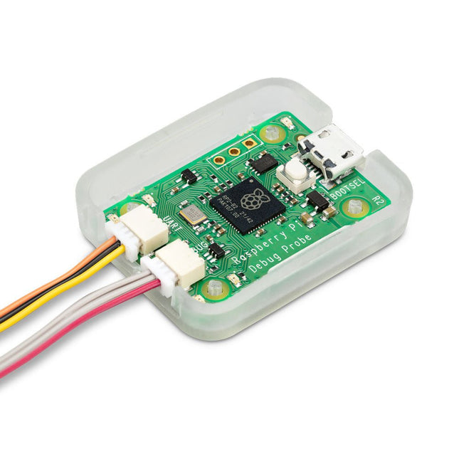
De Raspberry Pi Debug Probe is een alles-in-één USB-naar-debug-kit die alle benodigde hardware en kabels biedt voor eenvoudig, soldeerloos, plug-and-play debuggen.
Het beschikt over zowel een seriële debug-interface voor de processor (standaard de ARM Serial Wire Debug-interface, maar andere interfaces kunnen worden ondersteund) en een industriestandaard UART-interface. Beide interfaces gebruiken de Raspberry Pi 3-pins debug-connector.
Het is ontworpen om het debuggen en programmeren van Raspberry Pi Pico en RP2040 gemakkelijk te maken met een reeks hostplatforms, waaronder Windows, Mac en typische Linux-computers.
Hoewel de Debug Probe ontworpen is voor gebruik met Raspberry Pi-producten, biedt hij standaard UART- en CMSIS-DAP-interfaces via USB, zodat hij ook met andere processors kan worden gebruikt, of zelfs gewoon als USB-naar-UART-kabel. Het werkt met OpenOCD en andere tools die CMSIS-DAP ondersteunen.
De Debug Probe is gebaseerd op Raspberry Pi Pico-hardware en draait op de open source Raspberry Pi Picoprobe-software. De firmware wordt op dezelfde manier bijgewerkt als de Raspberry Pi Pico-firmware, dus het is gemakkelijk om het apparaat up-to-date te houden met de nieuwste firmware of om aangepaste firmware te gebruiken.
Kenmerken
USB naar ARM Serial Wire Debug (SWD)-poort
USB naar UART-brug
Compatibel met de CMSIS-DAP standaard
Werkt met OpenOCD en andere tools die CMSIS-DAP ondersteunen
Open source, eenvoudig te upgraden firmware
Specificaties
Dimensions: 22 x 32 mm
Nominal I/O voltage: 3.3 V
Operating temperature: -20°C to +70°C
Inbegrepen
1x Raspberry Pi Debug Probe
1x Kunststof koffer
1x USB-kabel
3x Debug-kabels
3-pins JST-connector naar 3-pins JST-connectorkabel
3-pins JST-connector naar 0,1-inch header (vrouwelijk)
3-pins JST-connector naar 0,1-inch header (mannelijk)
Downloads
Datasheet
3-pin Debug Connector
Schematics
Diagram
Latest Firmware
I²C is ubiquitous, you can find it in your phone, in embedded electronics, in all microcontrollers, Raspberry Pi and computer motherboards. It's applicable in a wide variety of cases, but the only downside is that it might be difficult to learn using it properly and to avoid painful debugging.This device makes it easier for you to understand what's going on inside, as I²CDriver has a clear logic-analyzer display of the signal lines plus a graphical decoding of the I²C traffic.In addition, it continuously displays an address map of all attached I²C devices, so as you connect a device, it lights up on the map.The current and voltage monitoring let you catch electrical problems early. The included color-coded wires make hookup quite easy; no pinout diagram is required. It includes a separate 3.3 V supply for your devices, a high-side current meter, and programmable pullup resistors for both I²C lines.Thanks to 3 I²C ports you can hook up multiple devices simultaneously without any effort. I²CDriver comes with software to control it from:
a GUI
the command-line
C and C++ using a single source file
Python 2 and 3, using a module
You can control I²C hardware using the PC tools you’re familiar with and reduce the development time needed to get the device doing what you want it to.Calibrating devices like accelerometers, magnetometers, and gyroscopes is much simpler and faster when done directly on the PC through I²CDriver.Moreover, the built in display shows a heatmap of all active network nodes. So in an I²C network with multiple devices, you can see at a glance which ones are the most active.I²CDriver can dump all I²C traffic back to the PC. I²CDriver’s capture mode reliably records every bit to an exhaustive time-stamped log. This is really helpful for debug, analysis, and reverse-engineering. Supported formats include text, CSV, and VCD.Features
Open hardware: the design, firmware and all tools are under BSD license
Live display: shows you exactly what it’s doing all the time
Fast transfer: sustained I²C transfers at 400 and 100 kHz
USB power monitoring: USB line voltage monitor to detect supply problems, to 0.01 V
Target power monitoring: target device high-side current measurement, to 5 mA
I²C pullups: programmable I²C pullup resistors, with automatic tuning
Three I²C ports: three identical I²C ports, each with power and I²C signals
Jumpers: color coded jumpers included in each pledge level
3.3 output: output levels are 3.3 V, all are 5 V tolerant
Supports all I²C features: 7- and 10-bit I²C addressing, clock stretching, bus arbitration
Sturdy componentry: uses an FTDI USB serial adapter, and Silicon Labs automotive-grade EFM8 controller
Usage reporting: reports uptime, temperature, and running CRC of all traffic
Flexible control: GUI, command-line, C/C++, and Python 2/3 host software provided for Windows, Mac, and Linux
Details
Maximum power out current: up to 470 mA
Device current: up to 25 mA
Dimensions: 61 mm x 49 mm x 6 mm
Computer interface: USB 2.0, micro USB connector
Contents (I²CDriver Core)
1x I²CDriver
3x Set of hookup jumpers
SPIDriver shows you what’s happening on the SPI bus in real time, so no more guessing about the bus state. Its purpose is to make understanding the functioning of SPI hardware more intuitive. It's useful if you're into debugging hardware or simply introduce a class to SPI for the first time.You can directly control LEDs and LCD displays just by having SPIDriver and you won't have to deal with microcontrollers. It's also a useful tool for examining, backing up and cloning an SPI flash as well as reading and writing SPI flash in circuit.SPIDriver is also applicable if you want to drive, test and evaluate different displays.With the help of current and voltage monitoring you'll be able to detect electrical problems at early stages. Thanks to the included color coded wires you can hook SPIDriver up without much effort; no pinout diagram required. It includes 3.3 V and 5 V supplies for your device, plus a high-side current meter.SPIDriver comes with software to control it from:
a GUI
the command-line
C and C++ using a single source file
Python 2 and 3, using a module
Technical features
Live display shows you exactly what it’s doing all the time
Sustained SPI transfers at 500 Kbps
USB line voltage monitor to detect supply problems, to 0.01 V
Target device high-side current measurement, to 5 mA
Two auxiliary output signals, A and B
Two dedicated power outlines: of 3.3 V and 5 V
All signals color coded to match jumper colors
All signals are 3.3 V, and are 5 V tolerant
Uses an FTDI USB serial adapter, and Silicon Labs automotive-grade EFM8 controller
Also reports uptime, temperature, and running CRC of all traffic
All sensors and signals controlled using a simple serial protocol
GUI, command-line, C/C++, and Python 2/3 host software provided for Windows, Mac, and Linux
Details
Maximum power out current: up to 470 mA
Signal current: up to 10 mA
Device current: up to 25 mA
Dimensions: 61 mm x 49 mm x 6 mm
Interface: USB 2.0, micro USB connector
Contents (SPIDriver Core)
1x SPIDriver
1x Set of hookup jumpers
De Soldered CONNECT Programmer is ontworpen om programmeerborden gebaseerd op ESP8266 en ESP32 microcontrollers extreem eenvoudig te maken. Hij bevat alle benodigde elektronica en logica, waardoor programmeren eenvoudig is door simpelweg een USB-kabel in de CONNECT Programmer te steken en deze aan te sluiten op de programmeerheader. De ingebouwde schakeling regelt automatisch de timing en signaalsequentie, waardoor de ESP-microcontroller in de bootloadermodus wordt gezet zonder handmatige tussenkomst.
Kenmerken
IC: CH340
Pin-indeling: GPIO0, RESET, RX, TX, 3V3, GND
LED's: RX, TX, voeding
Interface: USB-C
Afmetingen: 38 x 22 mm
Downloads
Datasheet
GitHub
De JLINK V9 Arm USB-JTAG emulator/debugger is een krachtige en betrouwbare tool voor het programmeren en debuggen van ARM Cortex-M, Cortex-A/R en andere ondersteunde microcontrollers via JTAG- en SWD-interfaces.
Kenmerken
Universele compatibiliteit: Ondersteunt een breed scala aan ARM-gebaseerde MCU's en cores, waaronder Cortex-M0, M3, M4, M7, A5, A7, A9 en R4.
Hoge snelheid: Snelle gegevensdoorvoer voor zowel flashprogrammering als realtime debuggen met minimale latentie.
Ondersteuning voor meerdere interfaces: Biedt zowel JTAG- als SWD-modi, wat flexibel gebruik in verschillende ontwikkelomgevingen mogelijk maakt.
Plug & Play via USB: Eenvoudige aansluiting op uw pc met USB 2.0-interface; Geen externe voeding nodig.
Robuuste softwareondersteuning: volledig compatibel met SEGGER J-Link-softwaretools en ondersteund door belangrijke IDE's, waaronder Keil MDK, IAR EWARM, SEGGER Embedded Studio en andere.
Inbegrepen
1x JLINK V9 USB-JTAG Arm emulator/debugger
1x USB-kabel
1x Verbindingskabel