Trade products
-

Weller Weller WT1013 Digitaal Soldeerstation (95 W)
The Weller WT 1013 soldering station set includes the WT 1 supply unit, the WP 80 soldering iron and the WSR 201 safety rest. It is stackable and thus creates more space in the workplace. With an integrated usage sensor, the soldering tool switches off automatically. Specifications Channels 1 Voltage 230 V Power 95 W Display Backlit LCD Temperature range 50 °C - 450 °C Temperature stability ±2 °C Temperature accuracy ±9 °C Fuse 0.5 A Equipotential bonding on WT compatible on ESD-safe on Power cable EMEA Dimensions 149 x 138 x 101 mm Weight (approx.) 1.9 kg
€ 441,65
-
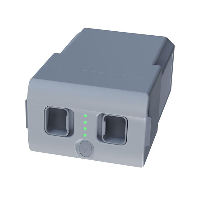
Unitree Unitree Go2 reservebatterij (15.000 mAh)
Met een capaciteit van 15.000 mAh biedt de Unitree Go2-batterij een robuuste stroombron waarmee uw robot taken met gemak kan uitvoeren. Of het nu gaat om complexe verkenningen, onderzoeksprojecten of leuke excursies, deze krachtige batterij levert de energie die uw robot nodig heeft. De looptijd van de Unitree Go2-batterij varieert afhankelijk van de toepassing en het gebruik. Op basis van de gebruikte functies en activiteiten kan de batterij tussen de 2 en 4 uur werken. Dankzij deze flexibiliteit kunt u de robot naar wens aanpassen, waardoor langere verkenningsmissies of uitgebreidere projecten mogelijk zijn. De Unitree Go2-batterij is een betrouwbare metgezel voor uw robotica-avonturen. Met zijn indrukwekkende capaciteit en aanpasbare looptijd zorgt hij ervoor dat uw robot krachtig en uithoudingsvermogen presteert, zonder regelmatig op te laden. Of u de Unitree Go2-batterij nu nodig heeft als vervanging of als upgrade voor uw robot, deze krachtige oplossing voor energieopslag biedt de perfecte balans tussen prestaties en betrouwbaarheid. Specificaties Nominale spanning: DC 28,8 V Beperkte laadspanning: DC 33,6 V Laadstroom: 9 A Nominale capaciteit: 15.000 mAh, 432 Wh Standaard: IS 16046 (deel 2) / IEC 62133-2 Zelf ontwikkeld batterijbeheersysteem (BMS) Afmetingen: 120 x 80 x 182 mm Kenmerken: Aan/uit-indicator Zelfontladingsbeveiliging van batterijopslag Evenwichtsladingsbescherming Bescherming tegen overbelasting Ontladingsbeveiliging Kortsluitbeveiliging Bescherming voor detectie van batterijlading
€ 795,00
Beste prijs
-
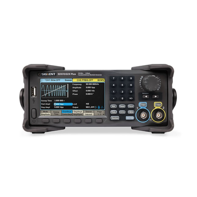
Siglent Siglent SDG1032X Plus 2-kanaals Arbitraire Golfvormgenerator (30 MHz)
De Siglent SDG1032X Plus is een krachtige dual-channel functie/willekeurige golfvormgenerator met een maximale frequentie van 30 MHz, een resolutie van 16 bits en een bemonsteringssnelheid van 1 GSa/s voor uitstekende signaalgetrouwheid. Het beschikt over TrueArb voor golfvormen met lage vervorming, EasyPulse voor jittervrije pulsen en robuuste sequentieweergave. Met een amplitude van ±10 V, een scherm van 4,3-inch en veelzijdige modulatie is dit een betrouwbare keuze voor ingenieurs en onderzoekers. Kenmerken Dual Channels: Onafhankelijke output met maximale frequentie van 30 MHz Hoge bemonsteringssnelheid: 1 GSa/s voor nauwkeurige golfvormgeneratie Hoge verticale resolutie: 16-bits resolutie voor nauwkeurige signaalreproductie TrueArb-technologie: Genereert willekeurige golfvormen met lage vervorming en hoge betrouwbaarheid EasyPulse-technologie: Produceert jittervrije blok- en pulssignalen met nauwkeurige controle over de stijg-/daltijden Willekeurige golfvormlengte: Ondersteunt tot 8 Mpts per kanaal voor complex golfvormontwerp Breed amplitudebereik: ±10 V maximale uitgangsamplitude Ingebouwde modulatiefuncties: AM, FM, PM, PWM, PSK, FSK, ASK en meer Multipulsuitgang: Maakt het meten van schakelparameters van elektrische apparatuur mogelijk PRBS-patroongeneratie: Ondersteunt tot 40 Mbps voor geavanceerde testbehoeften Sweep- en Burst-modi: Flexibele testmogelijkheden met aanpasbare parameters Sequence Playback-functie: Slaat complexe golfvormen efficiënt op en speelt deze af Frequentieteller: Meet frequenties tot 200 MHz met hoge precisie Gebruiksvriendelijk display: 4,3-inch kleuren-LCD met een duidelijke interface Ondersteuning voor afstandsbediening: Ingebouwde webserver voor bediening via een webbrowser Compact ontwerp: Draagbare en ruimtebesparende vormfactor Specificaties Bandbreedte 30 MHz Kanalen 2 Samplingsnelheid 1 GSa/s (4x interpolatie) Verticale resolutie 16 bits (per kanaal) Golfvormlengte 8 Mpts Max. amplitude ±10 V Display 4,3-inch TFT-LCD-kleurenscherm (480 x 272) Interfaces USB-host, USB-apparaat, LAN Afmetingen 260 x 107 x 296 mm Gewicht 4,35 kg Inbegrepen 1x Siglent SDG1032X Plus Arbitraire Golfvormgenerator 1x Netsnoer 1x USB-kabel 1x Garantiekaart 1x Quick Start Guide Downloads Datasheet User Manual Programming Guide Software
€ 446,49
-

Siglent Siglent SPD4306X 4-kanaals Voeding (400 W)
The Siglent SPD4306X is a 4-channel DC Linear Programmable Power Supply equipped with a 4.3-inch TFT-LCD display, friendly human-machine interface, and excellent performance indicators. Real-time waveform display provides engineers with an informative user interface. SPD4306X offers a total output power of 400 W with a resolution of 1 mV/1 mA. The maximum voltage and current for each channel are as follows: CH1: 15 V/1.5 A CH2: 30 V/6 A CH3: 30 V/6 A CH4: 15 V/1 A Kenmerken Rated output power: 400 W Rated voltage: 32 V, 12 V, 30 V Up to four high-precision power supplies with independent controllable outputs, supporting CH2 and CH3 series and parallel connections Clear graphical interface with waveform and timer display modes 5-digit voltage and current display with minimum resolution of 1 mV, 1 mA Fast output response time: <50us The high current channel support remote voltage compensation sense function. The maximum compensation voltage is 0.6 V Overvoltage protection and overcurrent protection or safe and accurate operation Equipped with a 4.3-inch TFT-LCD display (480 x 272 resolution) USB and LAN standard communication USB-GPIB module is optional Excellent channel density with up to 4 channels in a 3U half rack package Internal data storage for setups and parameters Embedded Web Server with instrument communication that doesn’t require software installation Fully SCPI programming command set support as well as a LabView driver for remote control and system automation Specificaties SPD4323X SPD4121X SPD4306X Channel Output CH1: Voltage 0 to 6 V Current 0 to 3.2 ACH2: Voltage 0 to 32 V Current 0 to 3.2 ACH3: Voltage 0 to 32 V Current 0 to 3.2 ACH4: Voltage 0 to 6 V Current 0 to 3.2 A CH1: Voltage 0 to 15 V Current 0 to 1.5 ACH2: Voltage 0 to 12 V Current 0 to 10 ACH3: Voltage 0 to 12 V Current 0 to 10 ACH4: Voltage 0 to 15 V Current 0 to 1.5 A CH1: Voltage 0 to 15 V Current 0 to 1.5 ACH2: Voltage 0 to 30 V Current 0 to 6 ACH3: Voltage 0 to 30 V Current 0 to 6 ACH4: Voltage 0 to 15 V Current 0 to 1 A Resolution 1 mV, 1 mA 1 mV, 1 mA 1 mV, 1 mA Setting Accuracy Voltage: ±(0.03% of reading+10) mV, Current: ±(0.3% of reading+10) mA Voltage: ±(0.03% of reading+10) mV, Current: ±(0.3% of reading+10) mA Voltage: ±(0.03% of reading+10) mV, Current: ±(0.3% of reading+10) mA Readback Accuracy Voltage: ±(0.03% of reading+10) mV, Current: ±(0.3% of reading+10) mA Voltage: ±(0.03% of reading+10) mV, Current: ±(0.3% of reading+10) mA Voltage: ±(0.03% of reading+10) mV, Current: ±(0.3% of reading+10) mA Display 4.3" TFT-LCD 5-digit voltage and current display 4.3" TFT-LCD 5-digit voltage and current display 4.3" TFT-LCD 5-digit voltage and current display Output power 240 W 285 W 400 W Inbegrepen 1x Siglent SPD4306X Power Supply 1x Power cord (EU) 1x Output test cord (3 A) 1x USB cable 1x Quick start guide Downloads Datasheet Manual Quick start
€ 1.101,10
-
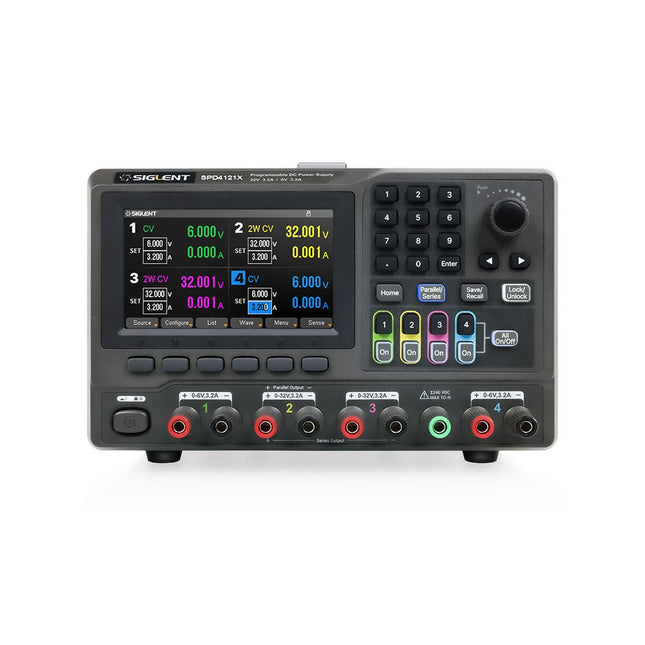
Siglent Siglent SPD4121X 4-kanaals Voeding (285 W)
The Siglent SPD4121X is a 4-channel DC Linear Programmable Power Supply equipped with a 4.3-inch TFT-LCD display, friendly human-machine interface, and excellent performance indicators. Real-time waveform display provides engineers with an informative user interface. SPD4121X offers a total output power of 285 W with a resolution of 1 mV/1 mA. The maximum voltage and current for each channel are as follows: CH1: 15 V/1.5 A CH2: 12 V/10 A CH3: 12 V/10 A CH4: 15 V/1.5 A Kenmerken Rated output power: 285 W Rated voltage: 32 V, 12 V, 30 V Up to four high-precision power supplies with independent controllable outputs, supporting CH2 and CH3 series and parallel connections Clear graphical interface with waveform and timer display modes 5-digit voltage and current display with minimum resolution of 1 mV, 1 mA Fast output response time: <50us The high current channel support remote voltage compensation sense function. The maximum compensation voltage is 0.6 V Overvoltage protection and overcurrent protection or safe and accurate operation Equipped with a 4.3-inch TFT-LCD display (480 x 272 resolution) USB and LAN standard communication USB-GPIB module is optional Excellent channel density with up to 4 channels in a 3U half rack package Internal data storage for setups and parameters Embedded Web Server with instrument communication that doesn’t require software installation Fully SCPI programming command set support as well as a LabView driver for remote control and system automation Specificaties SPD4323X SPD4121X SPD4306X Channel Output CH1: Voltage 0 to 6 V Current 0 to 3.2 ACH2: Voltage 0 to 32 V Current 0 to 3.2 ACH3: Voltage 0 to 32 V Current 0 to 3.2 ACH4: Voltage 0 to 6 V Current 0 to 3.2 A CH1: Voltage 0 to 15 V Current 0 to 1.5 ACH2: Voltage 0 to 12 V Current 0 to 10 ACH3: Voltage 0 to 12 V Current 0 to 10 ACH4: Voltage 0 to 15 V Current 0 to 1.5 A CH1: Voltage 0 to 15 V Current 0 to 1.5 ACH2: Voltage 0 to 30 V Current 0 to 6 ACH3: Voltage 0 to 30 V Current 0 to 6 ACH4: Voltage 0 to 15 V Current 0 to 1 A Resolution 1 mV, 1 mA 1 mV, 1 mA 1 mV, 1 mA Setting Accuracy Voltage: ±(0.03% of reading+10) mV, Current: ±(0.3% of reading+10) mA Voltage: ±(0.03% of reading+10) mV, Current: ±(0.3% of reading+10) mA Voltage: ±(0.03% of reading+10) mV, Current: ±(0.3% of reading+10) mA Readback Accuracy Voltage: ±(0.03% of reading+10) mV, Current: ±(0.3% of reading+10) mA Voltage: ±(0.03% of reading+10) mV, Current: ±(0.3% of reading+10) mA Voltage: ±(0.03% of reading+10) mV, Current: ±(0.3% of reading+10) mA Display 4.3" TFT-LCD 5-digit voltage and current display 4.3" TFT-LCD 5-digit voltage and current display 4.3" TFT-LCD 5-digit voltage and current display Output power 240 W 285 W 400 W Inbegrepen 1x Siglent SPD4121X Power Supply 1x Power cord (EU) 1x Output test cord (3 A) 1x USB cable 1x Quick start guide Downloads Datasheet Manual Quick start
€ 871,20
-

Holybro Holybro QAV 250 ARF Drone Kit
The QAV250 Kit is the perfect way to get started developing on either PX4 or Ardupilot. It pairs a carbon fiber 250 racing frame and essential electronics with Pixhawk 6C mini autopilot. The kit is easy to assemble. No soldering needed. Specifications Micro Power Module (PM06 v2) Motors: 2207 KV1950 Wheelbase: 250 mm Dimensions: 198 x 235 x 70 mm Weight: 347 g Included Carbon fiber 250 airframe with hardware Micro Power Module (PM06 v2) Motors: 2207 KV1950 5" Plastic Props Fully assembled Power Management Board with ESCs (BLHeli S ESC 20A) Battery Straps Note: LiPo battery is not included.
€ 214,95
Beste prijs
-
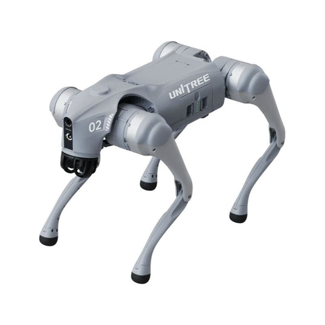
Unitree Unitree Go2 Edu Plus Viervoetige Robot
Tijdelijke vertraging in de levering van Unitree-robots Op dit moment ervaren wij, net als andere leveranciers, vertragingen in de levering van Unitree-robots. Een zending van onze leverancier staat vast bij de douane, waardoor we eerder geplaatste bestellingen later kunnen uitleveren dan gepland. We werken hier actief aan samen met onze leverancier en verwachten op korte termijn meer duidelijkheid, maar kunnen helaas geen garanties geven. Ook een nieuwe zending is onderweg, maar deze zal nog enige tijd op zich laten wachten. Omdat andere leveranciers met dezelfde uitdagingen te maken hebben, is overstappen naar een andere partij momenteel geen snellere oplossing. Onze prioriteit ligt bij het uitleveren van bestaande bestellingen. Mocht je vragen hebben of je bestelling willen aanpassen, neem dan gerust contact op met onze customer service. We houden je op de hoogte van verdere ontwikkelingen. Bedankt voor je geduld en vertrouwen! De Unitree Go2-serie bestaat uit viervoetige robots voor onderzoek en ontwikkeling van autonome systemen op het gebied van mens-robotinteractie (HRI), SLAM en transport. Dankzij de vier poten en de 12DOF kan deze robot op verschillende terreinen uit de voeten. De Go2 is uitgerust met een geperfectioneerd aandrijf- en energiebeheersysteem, dat een snelheid (afhankelijk van de uitvoering) tot 3,7 m/s of 11,88 km/u mogelijk maakt met een gebruiksduur tot 4 uur. Bovendien hebben de motoren een koppel van 45 Nm op het lichaam/dijen en de knieën, wat ook sprongen of backflips mogelijk maakt. Kenmerken Superherkenningssysteem: 4D LIDAR L1 Maximale loopsnelheid: ca. 5 m/s Maximale gewrichtskracht: ca. 45 Nm Draadloze module: WiFi 6/Bluetooth/4G Ultralange batterijduur: ca. 2-4 uur (lange batterijduur gemeten in de praktijk) Intelligent zijvolgsysteem: ISS 2.0 Specificaties Trackingmodule: Op afstand bestuurbaar of automatisch volgen Frontcamera: Beeldoverdrachtsresolutie 1280x720, gezichtsveld 120°, ultragroothoeklens voor rijke helderheid Frontlamp: Verlicht de weg voor u helder 4D LiDAR L1: 360° x 90° omnidirectionele ultragroothoekscanning maakt automatisch vermijden mogelijk met een kleine dode hoek en stabiele werking 12 kniegewrichtmotoren: Sterk en krachtig, mooi en eenvoudig, gloednieuwe visuele ervaring Intercommicrofoon: Effectieve communicatie zonder scenariobeperkingen Zelfoprollende riem: Gemakkelijk te dragen en te laden Stabieler, krachtiger met geavanceerde apparaten: 3D LiDAR, 4G ESIM-kaart, wifi 6 met dualband, Bluetooth 5.2 voor stabiele verbinding en bediening op afstand. Krachtige rekenkern: Bewegingscontroller, krachtige ARM-processor, verbeterde AI-algoritmeprocessor, externe ORIN NX/NANO. Slimme batterij: Standaard 8000 mAh-batterij, duurzame 15000 mAh-batterij, bescherming tegen oververhitting, overladen en kortsluiting. Luidspreker voor het afspelen van muziek: Luister naar muziek wanneer u dat wilt. Unitree Go2 varianten De Go2 overtuigt niet alleen met zijn technische mogelijkheden, maar ook met een modern en slank design dat hem een futuristische uitstraling geeft en een echte blikvanger maakt. De Go2 Air is speciaal ontworpen voor demo's en presentaties. Met zijn basisfuncties biedt hij een solide basis voor het demonstreren van de bewegingsmogelijkheden en functionaliteit van een viervoetige robot. Belangrijk: De Go2 Air wordt geleverd zonder controller. Deze is optioneel verkrijgbaar. Met een krachtige 8-core high-performance CPU bieden de Pro en Edu de indrukwekkende rekenkracht die nodig is voor complexe taken en veeleisende berekeningen. Dit maakt snellere en efficiëntere gegevensverwerking mogelijk en maakt de Pro en Edu een betrouwbare partner voor uw projecten. Vanaf de Edu-versie is de Go2 programmeerbaar en biedt hij eindeloze mogelijkheden voor het ontwikkelen en onderzoeken van uw eigen roboticatoepassingen. De Go2 kan ook een staphoogte tot 14 cm aan. Dit maakt het een ideaal hulpmiddel voor onderzoek, onderwijs en de instap in de wereld van robotica. De Go2 Edu wordt geleverd met een afstandsbediening die eenvoudige en intuïtieve bediening biedt. Je krijgt er ook een dockingstation bij met een indrukwekkende rekenkracht van 100 TOPS, dat is uitgerust met krachtige AI-algoritmen en technische ondersteuning biedt. De Go2 Edu is uitgerust met een krachtige accu van 15.000 mAh, goed voor een indrukwekkende gebruiksduur tot wel 4 uur. Deze lange gebruiksduur stelt de robot in staat om langere verkenningsmissies uit te voeren en veeleisende taken te voltooien. Modelvergelijking Air Pro Edu/Edu Plus Afmetingen (staand) 70 x 31 x 40 cm 70 x 31 x 40 cm 70 x 31 x 40 cm Afmetingen (hurkend) 76 x 31 x 20 cm 76 x 31 x 20 cm Materiaal Aluminiumlegering + zeer sterke technische kunststof Aluminiumlegering + zeer sterke technische kunststof Aluminiumlegering + zeer sterke technische kunststof kunststof Gewicht (met accu) ongeveer 15 kg ongeveer 15 kg ongeveer 15 kg Spanning 28~33,6 V 28~33,6 V Piekvermogen ongeveer 3000 W ongeveer 3000 W ongeveer 3000 W Laadvermogen ≈7 kg (MAX ~ 10 kg) ≈8 kg (MAX ~ 10 kg) ≈8 kg (MAX ~ 12 kg) Snelheid 0~2,5 m/s 0~3,5 m/s 0~3,7 m/s (MAX ~ 5 m/s) Maximale klim- en valhoogte ongeveer 15 cm ongeveer 16 cm ongeveer 16 cm Maximale klimhoek 30° 40° 40° Basisrekenkracht N.v.t. 8-core High-performance CPU 8-core high-performance CPU Aluminium kniegewrichtsmotor 12 stuks 12 stuks 12 stuks Intra-gewrichtscircuit (knie) ✓ ✓ ✓ Heatpipe-koeler ✓ ✓ ✓ Bewegingsbereik Behuizing: -48~48° Lichaam: -48~48° Lichaam: -48~48° Dij: -200°~90° Dij: -200°~90° Dij: -200°~90° Schacht: -156°~-48° Schacht: -156°~-48° Schacht: -156°~-48° Maximaal koppel N.v.t. ongeveer 45 N.m ongeveer 45 N.m Supergroothoek 3D LiDAR ✓ ✓ Draadloze vectorpositionering Module N.v.t. ✓ ✓ HD-groothoekcamera ✓ ✓ Voeteinde-krachtsensor N.v.t. N.v.t. ✓ Basisactie ✓ ✓ ✓ Automatisch schalen band N.v.t. ✓ N.v.t. Verbeterde Intelligent OTA ✓ ✓ ✓ RTT 2.0 Beeldoverdracht ✓ ✓ ✓ App Basis Afstandsbediening ✓ ✓ ✓ App Gegevensweergave ✓ ✓ ✓ App Grafisch Programma ✓ ✓ ✓ Koplamp (3 W) ✓ ✓ ✓ Wifi 6 met dualband ✓ ✓ ✓ Bluetooth 5.2/4.2/2.1 ✓ ✓ ✓ 4G-module N.v.t. CN/GB CN/GB Spraakfunctie N.v.t. ✓ ✓ Muziek afspelen N.v.t. ✓ ✓ ISS 2.0 Intelligent zijvolgsysteem N.v.t. ✓ ✓ Intelligente detectie en vermijding ✓ ✓ ✓ Secundaire ontwikkeling N/A N/A ✓ Handmatige controller Optioneel Optioneel ✓ Module met hoge rekenkracht N.v.t. N.v.t. Edu: TOP 40 rekenkracht Edu Plus: TOP 100 rekenkracht NVIDIA Jetson Orin (optioneel) Slimme batterij Standaard (8000 mAh) Standaard (8000 mAh) Lange batterijduur (15000 mAh) Batterijduur 1-2 uur 1-2 uur 2-4 uur Oplader Standaard (33,6 V, 3,5 A) Standaard (33,6 V, 3,5 A) Snelladen (33,6 V, 9 A) Inbegrepen 1x Unitree Go2 Edu Plus 1x Unitree Go2 afstandsbediening 1x Unitree Go2 batterij (15000 mAh) 1x Unitree Dockingstation met 100 TOPS rekenkracht Downloads Documentation iOS/Android apps GitHub
€ 14.999,00
Beste prijs
-
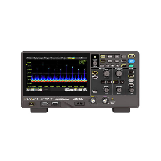
Siglent Siglent SDS822X HD 2-kanaals Oscilloscoop (200 MHz)
The Siglent SDS822X HD digital storage oscilloscope is based on 2 GSa/s, 12-bit Analog-Digital Converters and front ends with excellent noise floor performance. With a 200 MHz bandwidth, and a maximum record length of 100 Mpts, and the capability to analyze 2 analog channels alongside 16 digital channels, the SDS822X HD is perfectly suited for mixed signal analysis. Kenmerken 12-bit High Resolution 12-bit Analog-Digital Convertors with sample rate up to 2 GSa/s Front ends with 70 μVrms noise floor @ 200 MHz bandwidth 2/4 analog channels, up to 700 MHz bandwidth SPO technology Waveform capture rate up to 120,000 wfm/s (normal mode), and 500,000 wfm/s (sequence mode) Supports 256-level intensity grading and color temperature display modes. Up to 50 Mpts record length Digital trigger system Intelligent trigger: Edge, Slope, Pulse width, Window, Runt, Interval, Dropout, Pattern, Video (HDTV supported), Qualified, Nth edge, Delay, Setup/Hold time. Serial bus triggering and decoder, supports protocols I²C, SPI, UART, CAN, LIN. Segmented acquisition (Sequence) mode, dividing the maximum record length into multiple segments (up to 80,000), according to trigger conditions set by the user, with a very small dead time between segments to capture the qualifying event. History waveform record (History) function, the maximum recorded waveform length is 80,000 frames. Automatic measurements on 50+ parameters, supports statistics with histogram, track, trend, Gating measurement, and measurements on Math, History and Ref. 4 Math traces (2 Mpts FFT, addition, subtraction, multiplication, division, integration, differential, square root, etc.), supports formula editor. Abundant data analysis functions such as Search, Navigate, Counter, Bode plot and Power Analysis High Speed hardware-based Mask Test function, with Mask Editor tool for creating user-defined masks 16 digital channels (optional) 25 MHz waveform generator (optional) 7" TFT-LCD display with 1024 x 600 resolution; Capacitive touch screen supports multi-touch gestures. Interfaces include: USB Hosts, USB Device (USBTMC), LAN (VXI-11/Telnet/Socket), Pass/Fail, Trigger Out Built-in web server supports remote control over the LAN port using a web browser. Supports SCPI remote control commands. Supports external mouse and keyboard. Supports NTP. Specificaties Analog Channels 2 Bandwidth 200 MHz Vertical resolution 12-bit Sample rate (Max.) One channel mode: 100 Mpts/chTwo channel mode: Mpts/chFour channel mode: 25 Mpts/ch Memory depth (Max.) One channel mode: 50 Mpts/chTwo channel mode: 25 Mpts/ch Waveform capture rate (Max.) Normal mode: 120,000 wfm/sSequence mode: 500,000 wfm/s Trigger type Edge, Slope, Pulse width, Window, Runt, Interval, Dropout, Pattern, Video, Qualified, Nth edge, Delay, Setup/Hold time, Serial Serial trigger and decode (Standard) I²C, SPI, UART, CAN, LIN Measurement 50+ parameters, statistics, histogram, trend, and track supported Math 4 traces 2 Mpts FFT, Filter, +, -, x, ÷, ∫dt, d/dt, √, Identity, Negation, Absolute, Sign, ex, 10x, ln, lg, Interpolation, MaxHold, MinHold, ERES, Average. Supports formula editor Data analysis Search, Navigate, History, Mask Test, Counter, Bode plot, and Power Analysis Digital channel (optional) 16-channel; maximum sample rate up to 1 GSa/s; record length up to 10 Mpts USB AWG module (option) One channel, 25 MHz, sample rate of 125 MHz, wave length of 16 kpts, isolated output I/O 2x USB 2.0 Host, USB 2.0 Device, 10/100 M LAN, Auxiliary output (TRIG OUT, PASS/FAIL), SBUS (Siglent MSO) Probe (Standard) Passive probe PB470 for each channel Display 7 TFT-LCD with capacitive touch screen (1024x600) Inbegrepen 1x Siglent SDS822X Oscilloscope 2x Passive probe (200 MHz) PP520 1x Power cord (EU) 1x USB cable 1x Certificate of calibration 1x Quick start Downloads Datasheet Manual Programming guide
€ 635,25
-

Siglent Siglent SSA3032X Plus Spectrum Analyzer (9 kHz - 3,2 GHz)
De Siglent SSA3032X Plus spectrum analyzer is een krachtig en flexibel hulpmiddel voor RF signaal- en netwerkanalyse. Met een frequentiebereik van 3,2 GHz levert de analyzer betrouwbare automatische metingen en meerdere werkingsmodi: spectrum analyzer als basisfunctie, en optionele functies als RF-vermogensmeting, vectorsignaal-modulatieanalyse, reflectiemeting en EMI-test.Toepassingen zijn onder meer monitoring/evaluatie van zendsignalen, metingen op locatie, S-parameter meting, analoge/digitale modulatie analyse, EMI pre-compliance test, onderzoek en ontwikkeling, onderwijs, productie en onderhoud.Kenmerken Spectrum analyzer frequentiebereik van 9 kHz tot 3,2 GHz –161 dBm/Hz Displayed Average Noise Level (typ.) –98 dBc/Hz. @ 10 kHz Offset Phase Noise (1 GHz, typ.) Level Measurement Uncertainty< 0,7 dB (typ.) 1 Hz minimale Resolution Bandwidth (RBW) Voorversterker (standaard) Tracking generator (inbegrepen, gratis) Analoge en digitale signaalmodulatie-analyse modus (optioneel) Reflectie meetkit (optioneel) EMI filter en quasi-peak detector kit (optioneel) Advanced Measurement Kit (optioneel) 10,1-inch multi-touch scherm, muis en toetsenbord ondersteund Webbrowser afstandsbediening op pc en mobiele terminals, en bediening via files Specificaties SSA3015X Plus SSA3021X Plus SSA3032X Plus SSA3075X Plus Frequentiebereik 9 kHz ~ 1,5 GHz 9 kHz ~ 2,1 GHz 9 kHz ~ 3,2 GHz 9 kHz ~ 7,5 GHz Resolutie bandbreedte 1 Hz ~ 1 MHz 1 Hz ~ 1 MHz 1 Hz ~ 1 MHz 1 Hz ~ 3 MHz Phase Noise <–99 dBc/Hz <–98 dBc/Hz <–98 dBc/Hz <–98 dBc/Hz Total Amplitude Accuracy < 1,2 dB < 0,7 dB < 0,7 dB < 0,7 dB Display Average Noise Level –156 dBm/Hz –161 dBm/Hz –161 dBm/Hz –165 dBm/Hz Inbegrepen Siglent SSA3032X Plus spectrum analyzer USB kabel Netsnoer Quick Start gids Downloads Datasheet Manual Documentation Firmware
€ 2.951,19
-

Siglent Siglent SSA3015X Plus Spectrum Analyzer (9 kHz 1,5 gHz)
De Siglent SSA3015X Plus spectrum analyzer is een krachtig en flexibel hulpmiddel voor RF signaal- en netwerkanalyse. Met een frequentiebereik van 1,5 GHz levert de analyzer betrouwbare automatische metingen en meerdere werkingsmodi: spectrum analyzer als basisfunctie, en optionele functies als RF-vermogensmeting, vectorsignaal-modulatieanalyse, reflectiemeting en EMI-test.Toepassingen zijn onder meer monitoring/evaluatie van zendsignalen, metingen op locatie, S-parameter meting, analoge/digitale modulatie analyse, EMI pre-compliance test, onderzoek en ontwikkeling, onderwijs, productie en onderhoud.Kenmerken Spectrum analyzer frequentiebereik van 9 kHz tot 1,5 GHz –156 dBm/Hz Displayed Average Noise Level (typ.) –99 dBc/Hz. @ 10 kHz Offset Phase Noise (1 GHz, typ.) Level Measurement Uncertainty< 1,2 dB (typ.) 1 Hz minimale Resolution Bandwidth (RBW) Voorversterker (standaard) Tracking generator (inbegrepen, gratis) Analoge en digitale signaalmodulatie-analyse modus (optioneel) Reflectie meetkit (optioneel) EMI filter en quasi-peak detector kit (optioneel) Advanced Measurement Kit (optioneel) 10,1-inch multi-touch scherm, muis en toetsenbord ondersteund Webbrowser afstandsbediening op pc en mobiele terminals, en bediening via files Specificaties SSA3015X Plus SSA3021X Plus SSA3032X Plus SSA3075X Plus Frequentiebereik 9 kHz ~ 1,5 GHz 9 kHz ~ 2,1 GHz 9 kHz ~ 3,2 GHz 9 kHz ~ 7,5 GHz Resolutie bandbreedte 1 Hz ~ 1 MHz 1 Hz ~ 1 MHz 1 Hz ~ 1 MHz 1 Hz ~ 3 MHz Phase Noise <–99 dBc/Hz <–98 dBc/Hz <–98 dBc/Hz <–98 dBc/Hz Total Amplitude Accuracy < 1,2 dB < 0,7 dB < 0,7 dB < 0,7 dB Display Average Noise Level –156 dBm/Hz –161 dBm/Hz –161 dBm/Hz –165 dBm/Hz Inbegrepen Siglent SSA3015X Plus spectrum analyzer USB kabel Netsnoer Quick Start gids Downloads Datasheet Manual Documentation Firmware
€ 1.402,39
-
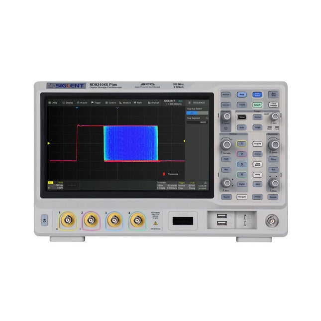
Siglent Siglent SDS2104X Plus 4-ch Oscilloscope (100 MHz)
Siglent's SDS2000X Plus series Digital Storage Oscilloscopes are available in bandwidths of 100 MHz, 200 MHz, and 350 MHz, have a maximum sample rate of 2 GSa/s, a maximum record length of 200 Mpts/ch, and up to 4 analog channels + 16 digital channels mixed-signal analysis ability. The SDS2000X Plus series employs Siglent’s SPO technology with a maximum waveform capture rate of up to 120,000 wfm/s (normal mode, up to 500,000 wfm/s in Sequence mode), 256-level intensity grading display function plus a color temperature display mode. It also employs an innovative digital trigger system with high sensitivity and low jitter. The trigger system supports multiple powerful triggering modes including serial bus triggering. History waveform recording, Sequence acquisition, Search and Navigate functions allow for extended waveform records to be captured, stored, and analyzed. An impressive array of measurement and math capabilities, options for a 50 MHz waveform generator, as well as serial decoding, mask test, bode plot, and power analysis are also features of the SDS2000X Plus. A 10-bit acquisition mode helps to satisfy applications that require more than 8-bit resolution. The large 10.1’’ capacitive touch screen supports multi-touch gestures, while the remote web control, mouse and external keyboard support greatly improve the operating efficiency of the SDS2000X Plus. Features 100 MHz, 200 MHz, 350 MHz (upgradable to 500 MHz) models Real-time sampling rate up to 2 GSa/s Record length up to 200 Mpts Serial bus triggering and decoder, supports I²C, SPI, UART, CAN, LIN, CAN FD, FlexRay, I²S and MIL-STD-1553B Provide 10 bit mode, Vertical and Horizontal Zoom Capacitive touch screen supports multi-touch gestures Siglent SDS2000X Plus Oscilloscopes SDS2102X Plus SDS2104X Plus SDS2204X Plus SDS2354X Plus Bandwidth 100 MHz 100 MHz 200 MHz 350 MHz Channels 2 4 4 4 Real-time sampling rate 2 GSa/s 2 GSa/s 2 GSa/s 2 GSa/s Capture rate 120,000 wfm/s 120,000 wfm/s 120,000 wfm/s 120,000 wfm/s Memory depth 200 Mpts/ch 200 Mpts/ch 200 Mpts/ch 200 Mpts/ch Included Siglent SDS2104X Plus Oscilloscope Passive probes Power cord USB cable Manual Downloads Datasheet Manual Quick guide User manual Firmware
€ 1.160,63
-

Siglent Siglent SDS2102X Plus 2-kanaals oscilloscoop (100 MHz)
De Siglent SDS2000X Plus serie oscilloscopen met digitale opslag zijn verkrijgbaar met bandbreedtes van 100 MHz, 200 MHz en 350 MHz, en hebben een maximale sample rate van 2 GSa/s, een maximale record length van 200 Mpts/ch, tot 4 analoge kanalen, en mixed-signal analysemogelijkheden tot 16 digitale kanalen. De SDS2000X Plus-serie maakt gebruik van de SPO technologie van Siglent met een maximale golfvorm capture snelheid van 120.000 wfm/s (bij normale modus, tot 500.000 wfm/s in Sequence modus), een 256-laags intensity grading weergavefunctie, plus een weergavemodus voor color temperature. Hij maakt ook gebruik van een innovatief digitaal triggersysteem met hoge gevoeligheid en lage jitter. Het triggersysteem ondersteunt meerdere krachtige triggermodi, waaronder seriële bustriggering. Functies als History Waveform Recording, Sequence Acquisition, Search en Navigate maken het mogelijk om uitgebreide golfvorm gegevens vast te leggen, op te slaan en te analyseren. Andere kenmerken van de SDS2000X Plus zijn de indrukwekkende reeks aan meet- en rekenmogelijkheden, de opties voor een 50 MHz golfvorm generator, en ook seriële decodering, mask test, bode plot en power analyse. De 10-bits acquisition modus is van nut bij toepassingen die een resolutie van meer dan 8 bits vereisen. Het grote capacitieve touchscreen van 10,1 inch ondersteunt multi-touch bewegingen, en ook is er ondersteuning voor webbediening op afstand, een muis en een extern toetsenbord, wat de bedieningsefficiëntie van de SDS2000X Plus aanzienlijk verbetert. Kenmerken 100 MHz, 200 MHz, 350 MHz (uitbreidbaar tot 500 MHz) modellen Real-time sample rate tot 2 GSa/s Record length tot 200 Mpts Seriële bustriggering en decoder, ondersteunt I²C, SPI, UART, CAN, LIN, CAN FD, FlexRay, I²S en MIL-STD-1553B Bied een 10-bits modus, verticale en horizontale zoom Capacitief touchscreen ondersteunt multi-touch bewegingen Siglent SDS2000X Plus oscilloscopen SDS2102X Plus SDS2104X Plus SDS2204X Plus SDS2354X Plus Bandbreedte 100 MHz 100 MHz 200 MHz 350 MHz Kanalen 2 4 4 4 Real-time sample rate 2 GSa/s 2 GSa/s 2 GSa/s 2 GSa/s Capture snelheid 120.000 wfm/s 120.000 wfm/s 120.000 wfm/s 120.000 wfm/s Memory depth 200 mf/ch 200 mf/ch 200 mf/ch 200 mf/ch Inbegrepen Siglent SDS2102X Plus oscilloscoop Passieve sondes Netsnoer USB kabel Handleiding Downloads Datasheet Service manual Quick guide Handleiding Firmware
€ 855,20
-

Elecrow Elecrow ThinkNode M5 – Meshtastic LoRa-transceiver (868 MHz)
Hoogwaardig LoRa-communicatieapparaat De Elecrow ThinkNode M5 is een compact, draagbaar LoRa-communicatieapparaat dat is ontworpen voor berichtenverkeer en het delen van locaties buiten het bereik van mobiele netwerken (off-grid) en voor gebruik in de buitenlucht. Het apparaat wordt aangestuurd door een ESP32-S3-processor en een SX1262 LoRa-chip, is voorzien van vooraf geïnstalleerde Meshtastic-firmware en kan eenvoudig via Bluetooth worden geconfigureerd met de officiële Meshtastic-app. De geïntegreerde multi-GNSS-module ondersteunt GPS, GLONASS, BeiDou en QZSS voor betrouwbare positionering en het delen van locaties. Berichten en apparaatgegevens worden weergegeven op het energiezuinige 1,54-inch e-paper-scherm, terwijl de ingebouwde oplaadbare accu van 1.200 mAh zorgt voor langdurig mobiel gebruik. Dankzij de geïntegreerde LoRa-antenne, de compacte behuizing, de RTC en de ondersteuning voor zowel Meshtastic- als MeshCore-firmware is de ThinkNode M5 een praktische communicatieoplossing voor wandelen, kamperen, afgelegen locaties en noodsituaties waarin conventionele mobiele netwerken niet beschikbaar zijn. Kenmerken LoRa-communicatie Multi-GNSS-positionering Oplaadbare accu van 1200 mAh 1,54-inch e-paper-display Ingebouwde RTC Compatibel met MeshCore Compatibel met Meshtastic Specificaties Hoofdprocessor (ESP32-S3) CPU/SoC Xtensa 32-bit LX7 dual-core processor, geklokt op maximaal 240 MHz Systeemgeheugen 512 KB SRAM, 8 MB PSRAM Opslag 4 MB Flash, 384 KB ROM Firmware Volledig compatibel met Meshtastic-firmware; signaaloverdracht via LoRa-modus EPD (Electronic Paper Display) Displaygrootte 1,54-inch EPD (monochroom E-Ink-scherm) Displaymateriaal E-Ink (Electronic Ink) Resolutie 200 x 200 Driver-chip SSD1681 (via SPI- of I²C-interface) Volledige verversingstijd 2 s Draadloze communicatie Bluetooth Bluetooth Low Energy en Bluetooth 5.0 (configuratie via telefoon) LoRa SX1262 LoRa-module, EU 868 MHz (externe antenne) Hardware Interfaces USB-C, RP-SMA Functies GPS-locatie (GPS, GLONASS, BeiDou, QZSS), EPD-scherm, RTC, USB 2.0, PMU-energiebeheer (ingebouwde 1200 mAh-lithiumaccu), zoemer, enz. Knoppen Draaischakelaar, functieknop, paginaknop, GPS-schakelaar, resetknop LED-indicator Voeding, GPS/LoRa-indicatie Overige Voeding 5 V/1 A, ondersteunt voeding via USB of lithiumbatterij Stroomverbruik De maximale bedrijfsstroom bedraagt ongeveer 340 mA (CPU + LoRa-module); het verbruik in de energiezuinige modus bedraagt ongeveer 34 uA Bedrijfstemperatuur -10~50°C Opslagtemperatuur -20~60°C Relatieve luchtvochtigheid 10-95% bij 40°C (niet-condenserend) Behuizing ABS-kunststof Afmetingen 82 x 51,6 x 26,3 mm Gewicht 81 g Inbegrepen 1x Elecrow ThinkNode M5 1x LoRa-antenne 1x USB-C kabel 1x Manual Downloads Manual
€ 74,95
Leden: € 67,46
-
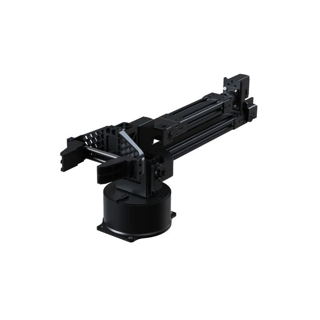
Unitree Unitree Go2 D1 Servo Robotarm
De Unitree Go2 D1 Servo Robotarm is een hoogwaardige robotarm met 6-DOF, speciaal ontworpen voor naadloze integratie met de Unitree Go2 Quadruped Robot. Ontworpen voor flexibiliteit en precisie, is het een ideaal hulpmiddel voor onderwijs, onderzoek, automatisering en geavanceerde robotica-ontwikkeling. Met zes volledig scharnierende gewrichten en een geïntegreerde grijper biedt de D1 echte zesassige beweging en uitzonderlijke bewegingsvrijheid. Met ondersteuning voor positie-, snelheids- en krachtregeling maakt hij nauwkeurige bediening mogelijk bij een breed scala aan taken – van implementatie in de praktijk tot experimentele leeromgevingen. De arm is gemaakt van lichtgewicht aluminiumlegering en weegt slechts 2,37 kg, terwijl een bereik van 670 mm behouden blijft. Deze balans tussen kracht en wendbaarheid maakt hem uitermate geschikt voor mobiele toepassingen, zonder dat dit ten koste gaat van de stabiliteit of het bereik. Dankzij de dual-level interface-architectuur ondersteunt de D1 zowel low-level motorische commando's als high-level gedragsprogrammering. Dit geeft ontwikkelaars, docenten en onderzoekers volledige controle, of ze nu bewegingssequenties verfijnen of complexe robotworkflows bouwen. Compatibel met externe componenten zoals camera's of mobiele robotchassis, opent de Unitree D1 de deur naar een breed scala aan toepassingen. Of het nu gaat om autonome objectmanipulatie, AI-training of praktische robotica-educatie, de D1 transformeert elke omgeving in een dynamisch en interactief innovatieplatform. Specificaties DoF 6 assen + 1 grijper Laadvermogen 500 g Armbereik 550 mm (grijper niet inbegrepen)670 mm (grijper inbegrepen) Interfaces DC5.5-2.1 (voeding)RJ45 (communicatie)USB-C (debuggen seriële poort) Motortype Busservo Vermogen 60 W Gewicht 2,37 kg Rotatiebereik van de gewrichten J1: ±135°J2: ±90°J3: ±90°J4: ±135°J5: ±90°J6: ±135°
€ 4.599,00
Beste prijs
-
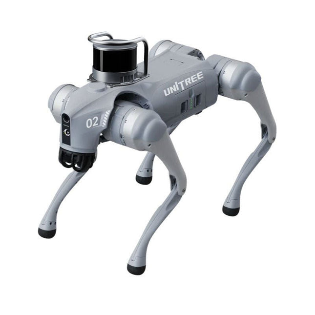
Unitree Unitree Go2 Edu Plus 3D LiDAR Viervoetige Robot
Tijdelijke vertraging in de levering van Unitree-robots Op dit moment ervaren wij, net als andere leveranciers, vertragingen in de levering van Unitree-robots. Een zending van onze leverancier staat vast bij de douane, waardoor we eerder geplaatste bestellingen later kunnen uitleveren dan gepland. We werken hier actief aan samen met onze leverancier en verwachten op korte termijn meer duidelijkheid, maar kunnen helaas geen garanties geven. Ook een nieuwe zending is onderweg, maar deze zal nog enige tijd op zich laten wachten. Omdat andere leveranciers met dezelfde uitdagingen te maken hebben, is overstappen naar een andere partij momenteel geen snellere oplossing. Onze prioriteit ligt bij het uitleveren van bestaande bestellingen. Mocht je vragen hebben of je bestelling willen aanpassen, neem dan gerust contact op met onze customer service. We houden je op de hoogte van verdere ontwikkelingen. Bedankt voor je geduld en vertrouwen! De Unitree Go2-serie bestaat uit viervoetige robots voor onderzoek en ontwikkeling van autonome systemen op het gebied van mens-robotinteractie (HRI), SLAM en transport. Dankzij de vier poten en de 12DOF kan deze robot op verschillende terreinen uit de voeten. De Go2 is uitgerust met een geperfectioneerd aandrijf- en energiebeheersysteem, dat een snelheid (afhankelijk van de uitvoering) tot 3,7 m/s of 11,88 km/u mogelijk maakt met een gebruiksduur tot 4 uur. Bovendien hebben de motoren een koppel van 45 Nm op het lichaam/dijen en de knieën, wat ook sprongen of backflips mogelijk maakt. Kenmerken Superherkenningssysteem: 4D LIDAR L1 Maximale loopsnelheid: ca. 5 m/s Maximale gewrichtskracht: ca. 45 Nm Draadloze module: WiFi 6/Bluetooth/4G Ultralange batterijduur: ca. 2-4 uur (lange batterijduur gemeten in de praktijk) Intelligent zijvolgsysteem: ISS 2.0 Specificaties Trackingmodule: Op afstand bestuurbaar of automatisch volgen Frontcamera: Beeldoverdrachtsresolutie 1280x720, gezichtsveld 120°, ultragroothoeklens voor rijke helderheid Frontlamp: Verlicht de weg voor u helder 4D LiDAR L1: 360° x 90° omnidirectionele ultragroothoekscanning maakt automatisch vermijden mogelijk met een kleine dode hoek en stabiele werking 12 kniegewrichtmotoren: Sterk en krachtig, mooi en eenvoudig, gloednieuwe visuele ervaring Intercommicrofoon: Effectieve communicatie zonder scenariobeperkingen Zelfoprollende riem: Gemakkelijk te dragen en te laden Stabieler, krachtiger met geavanceerde apparaten: 3D LiDAR, 4G ESIM-kaart, wifi 6 met dualband, Bluetooth 5.2 voor stabiele verbinding en bediening op afstand. Krachtige rekenkern: Bewegingscontroller, krachtige ARM-processor, verbeterde AI-algoritmeprocessor, externe ORIN NX/NANO. Slimme batterij: Standaard 8000 mAh-batterij, duurzame 15000 mAh-batterij, bescherming tegen oververhitting, overladen en kortsluiting. Luidspreker voor het afspelen van muziek: Luister naar muziek wanneer u dat wilt. Unitree Go2 varianten De Go2 overtuigt niet alleen met zijn technische mogelijkheden, maar ook met een modern en slank design dat hem een futuristische uitstraling geeft en een echte blikvanger maakt. De Go2 Air is speciaal ontworpen voor demo's en presentaties. Met zijn basisfuncties biedt hij een solide basis voor het demonstreren van de bewegingsmogelijkheden en functionaliteit van een viervoetige robot. Belangrijk: De Go2 Air wordt geleverd zonder controller. Deze is optioneel verkrijgbaar. Met een krachtige 8-core high-performance CPU bieden de Pro en Edu de indrukwekkende rekenkracht die nodig is voor complexe taken en veeleisende berekeningen. Dit maakt snellere en efficiëntere gegevensverwerking mogelijk en maakt de Pro en Edu een betrouwbare partner voor uw projecten. Vanaf de Edu-versie is de Go2 programmeerbaar en biedt hij eindeloze mogelijkheden voor het ontwikkelen en onderzoeken van uw eigen roboticatoepassingen. De Go2 kan ook een staphoogte tot 14 cm aan. Dit maakt het een ideaal hulpmiddel voor onderzoek, onderwijs en de instap in de wereld van robotica. De Go2 Edu wordt geleverd met een afstandsbediening die eenvoudige en intuïtieve bediening biedt. Je krijgt er ook een dockingstation bij met een indrukwekkende rekenkracht van 100 TOPS, dat is uitgerust met krachtige AI-algoritmen en technische ondersteuning biedt. De Go2 Edu is uitgerust met een krachtige accu van 15.000 mAh, goed voor een indrukwekkende gebruiksduur tot wel 4 uur. Deze lange gebruiksduur stelt de robot in staat om langere verkenningsmissies uit te voeren en veeleisende taken te voltooien. De Go2 Edu Plus 3D LiDAR wordt geleverd met een krachtige Hesai XT16 3D LiDAR. Deze LiDAR-sensor geeft de robot een nauwkeurige driedimensionale perceptie van zijn omgeving, wat zorgt voor soepele navigatie en intelligente obstakelontwijking. Modelvergelijking Air Pro Edu/Edu Plus Afmetingen (staand) 70 x 31 x 40 cm 70 x 31 x 40 cm 70 x 31 x 40 cm Afmetingen (hurkend) 76 x 31 x 20 cm 76 x 31 x 20 cm Materiaal Aluminiumlegering + zeer sterke technische kunststof Aluminiumlegering + zeer sterke technische kunststof Aluminiumlegering + zeer sterke technische kunststof kunststof Gewicht (met accu) ongeveer 15 kg ongeveer 15 kg ongeveer 15 kg Spanning 28~33,6 V 28~33,6 V Piekvermogen ongeveer 3000 W ongeveer 3000 W ongeveer 3000 W Laadvermogen ≈7 kg (MAX ~ 10 kg) ≈8 kg (MAX ~ 10 kg) ≈8 kg (MAX ~ 12 kg) Snelheid 0~2,5 m/s 0~3,5 m/s 0~3,7 m/s (MAX ~ 5 m/s) Maximale klim- en valhoogte ongeveer 15 cm ongeveer 16 cm ongeveer 16 cm Maximale klimhoek 30° 40° 40° Basisrekenkracht N.v.t. 8-core High-performance CPU 8-core high-performance CPU Aluminium kniegewrichtsmotor 12 stuks 12 stuks 12 stuks Intra-gewrichtscircuit (knie) ✓ ✓ ✓ Heatpipe-koeler ✓ ✓ ✓ Bewegingsbereik Behuizing: -48~48° Lichaam: -48~48° Lichaam: -48~48° Dij: -200°~90° Dij: -200°~90° Dij: -200°~90° Schacht: -156°~-48° Schacht: -156°~-48° Schacht: -156°~-48° Maximaal koppel N.v.t. ongeveer 45 N.m ongeveer 45 N.m Supergroothoek 3D LiDAR ✓ ✓ Draadloze vectorpositionering Module N.v.t. ✓ ✓ HD-groothoekcamera ✓ ✓ Voeteinde-krachtsensor N.v.t. N.v.t. ✓ Basisactie ✓ ✓ ✓ Automatisch schalen band N.v.t. ✓ N.v.t. Verbeterde Intelligent OTA ✓ ✓ ✓ RTT 2.0 Beeldoverdracht ✓ ✓ ✓ App Basis Afstandsbediening ✓ ✓ ✓ App Gegevensweergave ✓ ✓ ✓ App Grafisch Programma ✓ ✓ ✓ Koplamp (3 W) ✓ ✓ ✓ Wifi 6 met dualband ✓ ✓ ✓ Bluetooth 5.2/4.2/2.1 ✓ ✓ ✓ 4G-module N.v.t. CN/GB CN/GB Spraakfunctie N.v.t. ✓ ✓ Muziek afspelen N.v.t. ✓ ✓ ISS 2.0 Intelligent zijvolgsysteem N.v.t. ✓ ✓ Intelligente detectie en vermijding ✓ ✓ ✓ Secundaire ontwikkeling N/A N/A ✓ Handmatige controller Optioneel Optioneel ✓ Module met hoge rekenkracht N.v.t. N.v.t. Edu: TOP 40 rekenkracht Edu Plus: TOP 100 rekenkracht NVIDIA Jetson Orin (optioneel) Slimme batterij Standaard (8000 mAh) Standaard (8000 mAh) Lange batterijduur (15000 mAh) Batterijduur 1-2 uur 1-2 uur 2-4 uur Oplader Standaard (33,6 V, 3,5 A) Standaard (33,6 V, 3,5 A) Snelladen (33,6 V, 9 A) Inbegrepen 1x Unitree Go2 Edu Plus 3D LiDAR 1x Hesai XT16 3D LiDAR 1x Unitree Go2 afstandsbediening 1x Unitree Go2 batterij (15000 mAh) 1x Unitree Dockingstation met 100 TOPS rekenkracht Downloads Documentation iOS/Android apps GitHub
€ 20.599,00
Beste prijs
-

OWON OWON ADS924A 4-kanaals Oscilloscoop (250 MHz)
De OWON ADS900A-serie is een compacte 12-bits digitale oscilloscoop met een snelheid tot 2 GSa/s, een geheugen van 100 Mpts en een bandbreedte van 125/250 MHz. Met zijn 7-inch multi-touch display, FFT, protocoldecodering en geïntegreerde logic analyzer levert hij nauwkeurige signaalanalyse voor toepassingen in het laboratorium, de werkplaats en in het veld. Specificaties ADS914A ADS924A Bandwidth (-3 dB) 125 MHz 250 MHz Channels 4 Max. sample rate 2 GSa/s (single-channel) 1 GSa/s (dual-channel) 500 MSa/s (full-channel) DC Gain Accuracy 3% (≤1 mV) 2% (≥2 mV) Max memory depth 100M Vertical resolution 12 bits Relay time accuracy ±25 ppm (typical) Input Impedance 1 MΩ±2%, parallel with20 pF±5 pF Probe Attenuation Coefficient 1.00μX-1M.00X,step by 1-2-5, support custom Trigger type Edge, Video, Pulse, Slope, Runt, Windows, Timeout, Nth, Logic, RS232/UART, I²C, SPI CAN, LIN Bus decoding RS232/UART, I²C, SPI, CAN, LIN Auto measurement Period, Frequency, +Width, -Width, Rise Time, Fall Time, Scr Duty, +Duty,-Duty, Vavg, Vpp, VRMS, Overshoot, Vmax, Vmin, Vtop, CycRms, Vbase, Vamp, Preshoot, Std Dev, +Pulse Cnt, -Pulse Cnt, Rise Cnt, Fall Cnt, Area, Cyc Area, Delay(A↑-B↑), Delay(A↑-B↓), Delay(A↓-B↑), Delay(A↓-B↓), Phase(A↑-B↑) Phase(A↑-B↓), Phase(A↓-B↑), Phase(A↓-B↓), FRR(A↑-B↑), FRF(A↑-B↓) FFR(A↓-B↑), FFF(A↓-B↓), LRR(A↑-B↑), LRF(A↑-B↓), LFR(A↓-B↑), LFF(A↓-B↓) Waveform Math +, -, *, /, &&, ||, ^, !, Intg, Diff, Sqrt, Function operation (Lg / Ln / Exp / Abs / Sine / Cosine / Tan), FFT, FFT rms, User Defined, digital filter (low pass, high pass, band pass, band reject) Frequency counter 6-digit frequency counter Maximum frequency: maximum analog bandwidth of oscilloscope Voltmeter Support DC, AC+DCrms, ACrms, Resolution: 4 digits (ACV/DCV) Logical Analyzer Specifications Number of channels 16 input channels (D0-D15) (D0 to D7, D8 to D15) Max. input voltage ±40V peak CAT I, transient overvoltage 800Vpk Input Impedance 100kΩ, 8 pF Vertical resolution 1 bit Other Communication Interface HDMI, USB device, USB Host, Trig Out (P/F), LAN Display 7 inch (1024x600), capacitive multi-touch screen Power supply interface USB-C Dimensions 260 x 160 x 78 mm Weight 1.5 kg Inbegrepen 1x OWON ADS924A Oscilloscoop 1x Voedingsadapter 1x Netsnoer 1x USB-kabel 1x Probe 1x Quick Guide Downloads Manual Quick Guide PC Software
€ 688,49
-

OWON OWON ADS914A 4-kanaals Oscilloscoop (125 MHz)
De OWON ADS900A-serie is een compacte 12-bits digitale oscilloscoop met een snelheid tot 2 GSa/s, een geheugen van 100 Mpts en een bandbreedte van 125/250 MHz. Met zijn 7-inch multi-touch display, FFT, protocoldecodering en geïntegreerde logic analyzer levert hij nauwkeurige signaalanalyse voor toepassingen in het laboratorium, de werkplaats en in het veld. Specificaties ADS914A ADS924A Bandwidth (-3 dB) 125 MHz 250 MHz Channels 4 Max. sample rate 2 GSa/s (single-channel) 1 GSa/s (dual-channel) 500 MSa/s (full-channel) DC Gain Accuracy 3% (≤1 mV) 2% (≥2 mV) Max memory depth 100M Vertical resolution 12 bits Relay time accuracy ±25 ppm (typical) Input Impedance 1 MΩ±2%, parallel with20 pF±5 pF Probe Attenuation Coefficient 1.00μX-1M.00X,step by 1-2-5, support custom Trigger type Edge, Video, Pulse, Slope, Runt, Windows, Timeout, Nth, Logic, RS232/UART, I²C, SPI CAN, LIN Bus decoding RS232/UART, I²C, SPI, CAN, LIN Auto measurement Period, Frequency, +Width, -Width, Rise Time, Fall Time, Scr Duty, +Duty,-Duty, Vavg, Vpp, VRMS, Overshoot, Vmax, Vmin, Vtop, CycRms, Vbase, Vamp, Preshoot, Std Dev, +Pulse Cnt, -Pulse Cnt, Rise Cnt, Fall Cnt, Area, Cyc Area, Delay(A↑-B↑), Delay(A↑-B↓), Delay(A↓-B↑), Delay(A↓-B↓), Phase(A↑-B↑) Phase(A↑-B↓), Phase(A↓-B↑), Phase(A↓-B↓), FRR(A↑-B↑), FRF(A↑-B↓) FFR(A↓-B↑), FFF(A↓-B↓), LRR(A↑-B↑), LRF(A↑-B↓), LFR(A↓-B↑), LFF(A↓-B↓) Waveform Math +, -, *, /, &&, ||, ^, !, Intg, Diff, Sqrt, Function operation (Lg / Ln / Exp / Abs / Sine / Cosine / Tan), FFT, FFT rms, User Defined, digital filter (low pass, high pass, band pass, band reject) Frequency counter 6-digit frequency counter Maximum frequency: maximum analog bandwidth of oscilloscope Voltmeter Support DC, AC+DCrms, ACrms, Resolution: 4 digits (ACV/DCV) Logical Analyzer Specifications Number of channels 16 input channels (D0-D15) (D0 to D7, D8 to D15) Max. input voltage ±40V peak CAT I, transient overvoltage 800Vpk Input Impedance 100kΩ, 8 pF Vertical resolution 1 bit Other Communication Interface HDMI, USB device, USB Host, Trig Out (P/F), LAN Display 7 inch (1024x600), capacitive multi-touch screen Power supply interface USB-C Dimensions 260 x 160 x 78 mm Weight 1.5 kg Inbegrepen 1x OWON ADS914A Oscilloscoop 1x Voedingsadapter 1x Netsnoer 1x USB-kabel 1x Probe 1x Quick Guide Downloads Manual Quick Guide PC Software
€ 579,59
-
Unitree Unitree Go2 Remote Controller
De Unitree Go2 Controller is een speciaal afstandsbedieningsapparaat dat is ontworpen voor een naadloze en nauwkeurige bediening van de Unitree Go2 Quadruped Robot. Deze bimanuele afstandsbediening beschikt over ingebouwde gegevensoverdracht en Bluetooth-modules, wat betrouwbare draadloze communicatie met de robot mogelijk maakt. Het biedt een ultralange besturingsafstand van meer dan 100 meter in open omgevingen, wat flexibiliteit in verschillende operationele scenario's garandeert. Specificaties Laadspanning 5 V Laadstroom 2 A Frequentie 2,4 GHz Communicatiemodi Datatransmissiemodule en Bluetooth Batterijcapaciteit 2500 mAh Bedrijfstijd ca. 4,5 uur Bedieningsafstand Meer dan 100 meter in open omgevingen
€ 299,00
Beste prijs
-
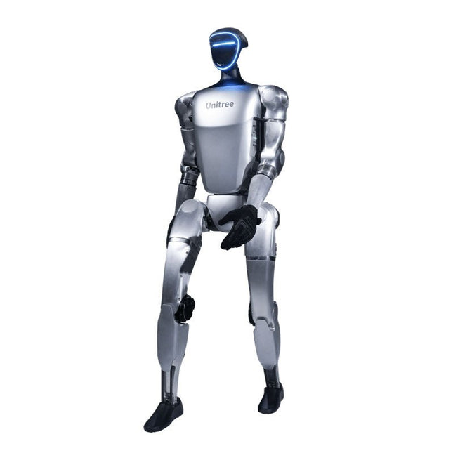
Unitree Unitree G1 Humanoid Robot
De Unitree G1 is een moderne humanoïde robot die indruk maakt met zijn opmerkelijke flexibiliteit en geavanceerde technologie. Met een uitzonderlijk groot bereik aan gewrichtsbewegingen en tot 43 gewrichtsmotoren overtreft hij de beweeglijkheid van een doorsnee mens. Aangedreven door imitatie- en versterkingsleren worden zijn robotsystemen voortdurend ontwikkeld en geoptimaliseerd met behulp van kunstmatige intelligentie. Een van de meest indrukwekkende eigenschappen van de G1 is zijn vermogen om autonoom in een wandelpositie te komen zodra hij de grond raakt – hulp van buitenaf is niet nodig! Hij kan onmiddellijk in beweging komen, wat getuigt van een hoge mate van onafhankelijkheid en aanpassingsvermogen. De G1 is ook uitgerust met een krachtgestuurde, zeer behendige hand die zowel gevoelig als nauwkeurig werkt, dankzij de combinatie van kracht- en positiecontrole. Deze hand bootst menselijke bewegingen nauwkeurig na, waardoor objecten nauwkeurig kunnen worden gemanipuleerd. Kenmerken Intel RealSense D435 dieptecamera Livox MID-360 3D LiDAR Microfoonarray (ruis- en echo-onderdrukking) 5 W stereoluidspreker Extra grote batterij met snelsluiting Vrijheidsgraden met één arm (schouder 2 + elleboog 2) Interne bekabeling van de gewrichten in de hele machine (geen externe kabels) Maximaal koppel op verbindingen 120 N.m Vrijheidsgraden met één been (heup 3, knie 1, enkel 2) Bewegingssnelheid van 2 m/s Specifications Hoogte, breedte en dikte (staand) 1320 x 450 x 200 mm Hoogte, breedte en dikte (gevouwen) 690 x 450 x 300 mm Gewicht (met batterij) ca. 35 kg Totale vrijheidsgraden(Gezamenlijke vrijheid 23 Vrijheidsgraden met één been 6 Vrijheidsgraden in de taille 1 Vrijheidsgraden met één arm 5 Gezamenlijke uitgangslager Gekruiste rollagers van industriële kwaliteit (hoge precisie, hoog draagvermogen) Gewrichtsmotor PMSM met interne rotor met lage traagheid en hoge snelheid (synchrone motor met permanente magneet – betere responssnelheid en warmteafvoer) Maximale koppel van het kniegewricht 90 Nm Maximale armbelasting ca. 2 kg Kuit- en dijlengte 0,6 m Armspanwijdte ca. 0,45 m Extra grote gewrichtsbewegingsruimte • Taillegewricht: Z ±155°• Kniegewricht: 0~165°• Heupgewricht: P ±154°, R -30~+170°, Y ±158° Volledige holle elektrische routering Ja Gezamenlijke encoder Dubbele encoder Koelsysteem Lokale luchtkoeling Voeding 13-snarige lithiumbatterij Basiscomputerkracht Hoogwaardige CPU met 8 kernen Detectiesensor Dieptecamera + 3D LiDAR Microfoons 4 microfoonarray Luidspreker 5 W stereoluidspreker Draadloos WiFi 6, Bluetooth 5.2 Slimme batterij (snelle ontgrendeling) 9000 mAh Oplader 54 V/5 A Handmatige bediening Ja Batterijduur ca. 2 uur Geüpgradede intelligente OTA Ja
€ 24.999,00
Beste prijs
-
UFactory UFactory 850 Robotic Arm
UFactory 850 is the most powerful robot with industrial grade performance. Features 6DoF Payload: 5 kg Reach: 850 mm Repeatability: 0.02 mm Weight: 20 kg Applications Glambot Welding Screwdriving Robot Vision Industrial Production Designed for both mobile platforms and your workbench The AC control box contains an AC-DC adapter inside, 100-240 V AC is all ready to go. The DC control box supports 48-72 V wide inputs, it perfectly fits the battery system on your mobile platform. Flexible Deployment With Safe Feature Hand teaching, space-saving and easy to re-deploy to multiple applications without changing your production layout. Perfectly for recurrent tasks. Collision detection is available for all of our cobots. Your safety is always the top priority. Graphical Interface For Beginner-Friendly Programming Compatible with various operation systems, including macOS and Windows. Web-based technology compatible with all major browsers. Drag and drop to create your code in minutes. Powerful And Open Source SDK At Your Fingertips Fully functional open-source Python/C++ SDK provides more flexible programming. ROS/ROS2 packages are ready-to-go. Example codes help you to deploy the robotic arm smoothly. Specifications UFactory 850 xArm 5 xArm 6 xArm 7 Payload 5 kg 3 kg 5 kg 3.5 kg Reach 850 mm 700 mm 700 mm 700 mm Degrees of freedom 6 5 6 7 Repeatability ±0.02 mm ±0.1 mm ±0.1 mm ±0.1 mm Maximum Speed 1 m/s 1 m/s 1 m/s 1 m/s Weight (robot arm only) 20 kg 11.2 kg 12.2 kg 13.7 kg Maximum Speed 180°/s 180°/s 180°/s 180°/s Joint 1 ±360° ±360° ±360° ±360° Joint 2 -132°?132° -118°?120° -118°?120° -118°?120° Joint 3 -242°~3.5° -225°~11° -225°~11° ±360° Joint 4 ±360° -97°~180° ±360° -11°?225° Joint 5 -124°~124° ±360° -97°~180° ±360° Joint 6 ±360° ±360° -97°~180° Joint 7 ±360° Hardware Ambient Temperature Range 0-50°C Power Consumption Typical 240 W, max 1000 W Input Power Supply 48 V DC, 20.8 A Footprint Ø 190 mm Materials Aluminum, Carbon Fiber Base Connector Type M8x4 ISO Class Cleanroom 5 Robot Mounting Any End Effector Communication Protocol Modbus RTU End Effector I/O 2x DI / 2x DO / 2x AI / 1x RS485 Communication Mode Ethernet Included 1x UFactory 850 robotic arm 1x AC control box 1x Control box power cable
€ 11.779,00
Beste prijs
-
UFactory UFactory xArm 7
This multi-axis robot perfectly balances power and size. Features 6 Axis Payload: 3.5 kg Reach: 700 mm Repeatability: 0.1 mm Max Speed 1000 mm/s Applications Machine Tending Bin Picking Mobile platform Lab Automation Robotic Research Durable Collaborative robots for your automation Industrial-grade harmonic drive and servomotors guarantee 24/7 working without stop. Crafted from Carbon fiber, 15 kg weight makes it possible for easier deployment. Flexible deployment with safe feature Hand teaching, lightweight, space-saving and easy to re-deploy to multiple applications without changing your production layout. Perfectly for recurrent tasks. Collision detection is available for all of our cobots. Your safety is always the top priority. Graphical interface for beginner-friendly programming Compatible with various of operation systems, including macOS and Windows. Web-based technology compatible with all major browsers. Drag and drop to create your code in minutes. Powerful and open source SDK at your fingertips Fully functional open-source Python/C++ SDK provides more flexible programming. ROS/ROS2 packages are ready-to-go. Example codes help you to deploy the robotic arm smoothly. Specifications UFactory 850 xArm 5 xArm 6 xArm 7 Payload 5 kg 3 kg 5 kg 3.5 kg Reach 850 mm 700 mm 700 mm 700 mm Degrees of freedom 6 5 6 7 Repeatability ±0.02 mm ±0.1 mm ±0.1 mm ±0.1 mm Maximum Speed 1 m/s 1 m/s 1 m/s 1 m/s Weight (robot arm only) 20 kg 11.2 kg 12.2 kg 13.7 kg Maximum Speed 180°/s 180°/s 180°/s 180°/s Joint 1 ±360° ±360° ±360° ±360° Joint 2 -132°?132° -118°?120° -118°?120° -118°?120° Joint 3 -242°~3.5° -225°~11° -225°~11° ±360° Joint 4 ±360° -97°~180° ±360° -11°?225° Joint 5 -124°~124° ±360° -97°~180° ±360° Joint 6 ±360° ±360° -97°~180° Joint 7 ±360° Hardware Ambient Temperature Range 0-50°C Power Consumption Min 8.4 W, Typical 200 W, max 400 W Input Power Supply 24 V DC, 16.5 A Footprint Ø 126 mm Materials Aluminum, Carbon Fiber Base Connector Type M5x5 ISO Class Cleanroom 5 Robot Mounting Any End Effector Communication Protocol Modbus RTU(rs485) End Effector I/O 2x DI/2x DO/2x AI/1x RS485 Communication Mode Ethernet Included 1x xArm 5 robotic arm 1x AC control box 1x Robotic arm power cable 1x Robotic arm end effector adapter cable 1x Robotic arm signal cable 1x Control box power cable 1x Network cable 1x Mounting tool 1x Quick start guide
€ 14.569,00
Beste prijs
-

UFactory UFactory xArm 6
This multi-axis robot perfectly balances power and size. Features Payload: 5 kg Reach: 700 mm Repeatability: 0.1 mm Max Speed 1000 mm/s Applications Machine Tending Bin Picking Mobile platform Lab Automation Robotic Research Durable Collaborative robots for your automation Industrial-grade harmonic drive and servomotors guarantee 24/7 working without stop. Crafted from Carbon fiber, 15 kg weight makes it possible for easier deployment. Flexible deployment with safe feature Hand teaching, lightweight, space-saving and easy to re-deploy to multiple applications without changing your production layout. Perfectly for recurrent tasks. Collision detection is available for all of our cobots. Your safety is always the top priority. Graphical interface for beginner-friendly programming Compatible with various of operation systems, including macOS and Windows. Web-based technology compatible with all major browsers. Drag and drop to create your code in minutes. Powerful and open source SDK at your fingertips Fully functional open-source Python/C++ SDK provides more flexible programming. ROS/ROS2 packages are ready-to-go. Example codes help you to deploy the robotic arm smoothly. Specifications UFactory 850 xArm 5 xArm 6 xArm 7 Payload 5 kg 3 kg 5 kg 3.5 kg Reach 850 mm 700 mm 700 mm 700 mm Degrees of freedom 6 5 6 7 Repeatability ±0.02 mm ±0.1 mm ±0.1 mm ±0.1 mm Maximum Speed 1 m/s 1 m/s 1 m/s 1 m/s Weight (robot arm only) 20 kg 11.2 kg 12.2 kg 13.7 kg Maximum Speed 180°/s 180°/s 180°/s 180°/s Joint 1 ±360° ±360° ±360° ±360° Joint 2 -132°?132° -118°?120° -118°?120° -118°?120° Joint 3 -242°~3.5° -225°~11° -225°~11° ±360° Joint 4 ±360° -97°~180° ±360° -11°?225° Joint 5 -124°~124° ±360° -97°~180° ±360° Joint 6 ±360° ±360° -97°~180° Joint 7 ±360° Hardware xArm Robot specs Ambient Temperature Range 0-50°C Power Consumption Min 8.4 W, Typical 200 W, max 400 W Input Power Supply 24 V DC, 16.5 A Footprint Ø 126 mm Materials Aluminum, Carbon Fiber Base Connector Type M5x5 ISO Class Cleanroom 5 Robot Mounting Any End Effector Communication Protocol Modbus RTU(rs485) End Effector I/O 2x DI/2x DO/2x AI/1x RS485 Communication Mode Ethernet Included 1x xArm 5 robotic arm 1x AC control box 1x Robotic arm power cable 1x Robotic arm end effector adapter cable 1x Robotic arm signal cable 1x Control box power cable 1x Network cable 1x Mounting tool 1x Quick start guide
€ 11.259,00
Beste prijs
-

UFactory UFactory xArm 5 Lite
This multi-axis robot perfectly balances power and size. Features 5 Axis Payload: 3 kg Reach: 700 mm Repeatability: 0.1 mm Max Speed 1000 mm/s Applications Machine Tending Bin Picking Mobile platform Lab Automation Robotic Research Durable Collaborative robots for your automation Industrial-grade harmonic drive and servomotors guarantee 24/7 working without stop. Crafted from Carbon fiber, 15 kg weight makes it possible for easier deployment. Flexible deployment with safe feature Hand teaching, lightweight, space-saving and easy to re-deploy to multiple applications without changing your production layout. Perfectly for recurrent tasks. Collision detection is available for all of our cobots. Your safety is always the top priority. Graphical interface for beginner-friendly programming Compatible with various of operation systems, including macOS and Windows. Web-based technology compatible with all major browsers. Drag and drop to create your code in minutes. Powerful and open source SDK at your fingertips Fully functional open-source Python/C++ SDK provides more flexible programming. ROS/ROS2 packages are ready-to-go. Example codes help you to deploy the robotic arm smoothly. Specifications UFactory 850 xArm 5 xArm 6 xArm 7 Payload 5 kg 3 kg 5 kg 3.5 kg Reach 850 mm 700 mm 700 mm 700 mm Degrees of freedom 6 5 6 7 Repeatability ±0.02 mm ±0.1 mm ±0.1 mm ±0.1 mm Maximum Speed 1 m/s 1 m/s 1 m/s 1 m/s Weight (robot arm only) 20 kg 11.2 kg 12.2 kg 13.7 kg Maximum Speed 180°/s 180°/s 180°/s 180°/s Joint 1 ±360° ±360° ±360° ±360° Joint 2 -132°?132° -118°?120° -118°?120° -118°?120° Joint 3 -242°~3.5° -225°~11° -225°~11° ±360° Joint 4 ±360° -97°~180° ±360° -11°?225° Joint 5 -124°~124° ±360° -97°~180° ±360° Joint 6 ±360° ±360° -97°~180° Joint 7 ±360° Hardware Ambient Temperature Range 0-50°C Power Consumption Min 8.4 W, Typical 200 W, max 400 W Input Power Supply 24 V DC, 16.5 A Footprint Ø 126 mm Materials Aluminum, Carbon Fiber Base Connector Type M5x5 ISO Class Cleanroom 5 Robot Mounting Any End Effector Communication Protocol Modbus RTU(rs485) End Effector I/O 2x DI/2x DO/2x AI/1x RS485 Communication Mode Ethernet Included 1x xArm 5 robotic arm 1x AC control box 1x Robotic arm power cable 1x Robotic arm end effector adapter cable 1x Robotic arm signal cable 1x Control box power cable 1x Network cable 1x Mounting tool 1x Quick start guide
€ 7.285,00
Beste prijs
-
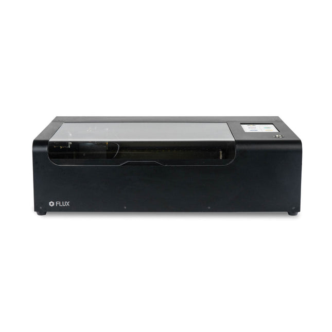
FLUX FLUX Beamo Laser Cutter
FLUX Beamo is a powerful and compact 30 W CO2 desktop laser cutter that can cut and engrave a range of materials including metals. With its easy-to-use design, intuitive controls and features, you can effortlessly create amazing things. Built-in HD camera Cutting and engraving is hassle-free with our preview mode. Place your material, preview the work area in the Beam Studio software and engrave. Your design comes out exactly as shown in the preview. Integrated safety features If left opened, auto pause ensures the laser stops. The internal water cooling system provides a stable cutting process. Plus, you can stop production with a single switch at any time. Powerful high resolution laser The Beamo ultra thin laser can engrave exceptional detail down to 0.05 mm wide with a clear resolution of 1,000 dpi. Fitting for any craft or small business project. The most precise compact CO2 laser engraver Beamo's sleek, modern and compact design fits beautifully in any home, school or workshop space. It comes pre-assembled with a metal body and acrylic lid, measuring 615 x 445 x 177 mm. Bring your designs to life with its 30 W CO2 laser operating on a 30 x 21 cm work area. Safe for home and school Beamo prioritises safety with its thoughtful design features. The machine is fully enclosed, and it automatically pauses if the lid is opened during a task. Additionally, there is a single switch for immediate machine shutdown in case of emergencies. Beamo is equipped with a Class 1 laser, which is completely safe under normal use. Specifications Dimensions 615 x 445 x 177 mm Weight 22 kg Work Area 300 x 210 x 45 mm (11.81 x 8,27 x 1.77") Camera Preview Area 300 x 195 mm Voltage AC 110 V / 220 V Touch Panel 1024 x 600 LCD Camera HD CMOS I/O Wi-Fi / Ethernet Laser Spec 30 W CO? Laser Laser Moving Speed 0~300 mm/s Laser Cutting Thickness 0-5 mm (varies by material) Software Mode Vector / Graphic (monochrome, gray scale) Operating System Windows / macOS / Linux Software File Type JPG / PNG / SVG / DXF Included FLUX Beamo (distilled water included) Vent hose Duct Clamp Double sided tape to align the mirror's Ethernet cable Vent Hose Double head wrench Wood piece Torx screwdriver and 2.5 mm hexagonal wrench Funnel 1x Laser Cutter Lubricant Power cord Wifi Dongle USB Beamo Manual Honey Comb Platform (30 W) Downloads Firmware
€ 2.660,00
Beste prijs


