Raspberry Pi Pico Breadboard Kit helps the user to configure GPIO of Raspberry Pi Pico for use with external devices.Raspberry Pi Pico Breadboard Kit is a multi-purpose Kit that consists of a “400 points half-size breadboard” on top, a Programmable Buzzer, 4 programmable LEDs, 4 push buttons, and dedicated 5 V, 3V3, and GND pins at a single place. SB Components developed Raspberry Pi Pico Breadboard Kit with advanced features like independently controllable LEDs, Switches, a 400 points half-size breadboard that helps the user to prototype their projects with Raspberry Pi Pico in an efficient way.Raspberry Pi Pico Breadboard Kit can be interfaced with Raspberry Pi Pico from which a user can run electronics experiments, prototypes, mini robots, games, interact with Linux-ready Raspberry Pi, Exploration of circuits, etc. One can also connect external components with the breadboard provided on the top of the Raspberry Pi Pico Breadboard Kit.Features
Four independent controlled LEDs
Four independent controlled push buttons
Compatible with Pico
A 400 points half size breadboard
Programmable buzzer
Dedicated 5 V, 3V3 and Gnd pins for easy use
Specifications
Operating voltage
3.3 VDC
Communication interface
GPIO
Dimensions
85 x 133 mm
Applications
Electrical experiments
Prototypes
Mini robots
Games
Exploration of circuits
Downloads
Manual
Example codes
Circuit diagram
GitHub
Included
1x Pico Breadboard Kit
5x Male to Male Jumper Wires
5x Female to Female Jumper Wires
5x Male to female Jumper Wires
Note: Raspberry Pi Pico is not included.
De Pico Cube is een 4x4x4 led kubus HAT voor Raspberry Pi Pico met 5 VDC bedrijfsspanning. De Pico Cube, een monochromatisch Groen met 64 leds, leert u op een leuke manier programmeren. Hij is ontworpen om lichtgevende bewerkingen te tonen met een laag energieverbruik, heeft een robuust ontwerp en is eenvoudig te installeren, waardoor mensen / kinderen / gebruikers de effecten op leds met een verschillend kleurenpatroon leren kennen door software en hardware, zoals de Raspberry Pi Pico, te combineren. Kenmerken Standaard 40-pins Raspberry Pi Pico header GPIO-gebaseerde communicatie 64 high-intensity monochromatische leds Toegang tot individuele leds Toegang tot elke laag Specificaties Bedrijfsspanning: 5 V Kleur: groen Communicatie: GPIO Leds: 64 Inbegrepen 1x Pico Cube basis PCB 4x PCB lagen 8x PCB pilaren 2x berg strips (1 x 20), male 2x berg strips (1 x 20), female 70 leds Opmerking: Raspberry Pi Pico is niet inbegrepen. Downloads GitHub Wiki
De Pico Cube is een 4x4x4 led kubus HAT voor Raspberry Pi Pico met 5 VDC bedrijfsspanning. De Pico Cube, een monochromatisch Rood met 64 leds, leert u op een leuke manier programmeren. Hij is ontworpen om lichtgevende bewerkingen te tonen met een laag energieverbruik, heeft een robuust ontwerp en is eenvoudig te installeren, waardoor mensen / kinderen / gebruikers de effecten op leds met een verschillend kleurenpatroon leren kennen door software en hardware, zoals de Raspberry Pi Pico, te combineren. Kenmerken Standaard 40-pins Raspberry Pi Pico header GPIO-gebaseerde communicatie 64 high-intensity monochromatische leds Toegang tot individuele leds Toegang tot elke laag Specificaties Bedrijfsspanning: 5 V Kleur: rood Communicatie: GPIO Leds: 64 Inbegrepen 1x Pico Cube basis PCB 4x PCB lagen 8x PCB pilaren 2x berg strips (1 x 20), male 2x berg strips (1 x 20), female 70 leds Opmerking: Raspberry Pi Pico is niet inbegrepen. Downloads GitHub Wiki
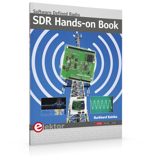
The short-wave technique has a very particular appeal: It can easily bridge long distances. By reflecting short-wave signals off the conductive layers of the ionosphere, they can be received in places beyond the horizon and therefore can reach anywhere on earth. Although technology is striving for ever higher frequencies, and radio is usually listened to on FM, DAB+, satellite or the Internet, modern means of transmission require extensive infrastructure and are extremely vulnerable. In the event of a global power outage, there is nothing more important than the short-wave. Amateur radio is not only a hobby, it’s also an emergency radio system!
Elektor’s SDR-Shield is a versatile shortwave receiver up to 30 MHz. Using an Arduino and the appropriate software, radio stations, morse signals, SSB stations, and digital signals can be received.
In this book, successful author and enthusiastic radio amateur, Burkhard Kainka describes the modern practice of software defined radio using the Elektor SDR Shield. He not only imparts a theoretical background but also explains numerous open source software tools.
De kortegolftechniek heeft een bijzondere aantrekkingskracht: Hij kan gemakkelijk grote afstanden overbruggen. Door kortegolfsignalen te weerkaatsen tegen de geleidende lagen van de ionosfeer, kunnen ze worden ontvangen op plaatsen voorbij de horizon en kunnen ze dus overal op aarde komen. Hoewel de technologie naar steeds hogere frequenties streeft en radio meestal op FM, DAB+, satelliet of internet wordt beluisterd, vereisen moderne transmissiewijzen een uitgebreide infrastructuur en zijn zij uiterst kwetsbaar. In geval van een wereldwijde stroomstoring is er niets belangrijker dan de kortegolf. Amateur radio is niet alleen een hobby, het is ook een noodradiosysteem! Elektor's SDR-Shield (SKU 18515) is een veelzijdige kortegolf ontvanger tot 30 MHz. Met behulp van een Arduino en de juiste software kunnen radiostations, morse signalen, SSB stations, en digitale signalen worden ontvangen.In dit boek beschrijft de succesvolle auteur en enthousiaste radioamateur Burkhard Kainka de moderne praktijk van software defined radio met behulp van het Elektor SDR Shield. Hij geeft niet alleen een theoretische achtergrond, maar legt ook tal van open source software tools uit.
De nRSP-ST is een op een netwerk aangesloten radio-ontvanger met algemene dekking voor frequenties van 1 kHz tot 2 GHz met een spectrumzichtbaarheid tot 10 MHz. De nRSP-ST is uw eigen persoonlijke, op afstand toegankelijke SDR die u ook kunt delen met een klein aantal vertrouwde vrienden of collega's.
De nRSP-ST komt tegemoet aan de behoeften van radioliefhebbers die een 'plug-and-play'-oplossing willen voor ontvangst op afstand. Naast dat we dit hebben bereikt, hebben we typische internetbandbreedtebeperkingen aangepakt door een nieuwe IQ Lite-modus te creëren, die op efficiënte wijze kanalen met IQ-gegevens levert. We introduceren ook de mogelijkheid om IQ-opnames op een externe locatie te beheren en op te slaan. De nRSP-ST is ideaal voor iedereen die een breedbandontvanger op afstand wil zonder computervaardigheden en urenlange insteltijd en doorlopend onderhoud op de externe locatie.
Kenmerken
"Plug and play" geïntegreerde, op een netwerk aangesloten ontvanger met algemene dekking:
Combineert een ontvanger, een hostcomputer en nog veel meer – alles in één doos!
Sluit de stroom aan en maak verbinding met internet (Ethernet of Wi-Fi) en de nRSP-ST is automatisch overal toegankelijk
Multi-platform SDRconnect-software ondersteunt lokale bediening of externe toegang op Windows-, MacOS- of Linux-platforms
De nRSP-ST & SDRconnect kan worden geconfigureerd voor de beschikbare netwerkbandbreedte:
In de Full IQ-modus biedt de nRSP-ST IQ-gegevensoverdracht van de zichtbare spectrumbandbreedte (bijvoorbeeld voor hogesnelheids-LAN of supersnelle internetverbinding)
In de IQ Lite-modus levert de nRSP-ST IQ-gegevens van kanalen tot 192 kHz breed (bijvoorbeeld voor digitale decodering door de klant)
In de Compact modus levert de nRSP-ST gecomprimeerde audio (ideaal voor langzamere internetverbindingen)
Ondersteunt meerdere clientverbindingen met een gelijktijdige combinatie van verbindingsmodi. Met een beheerderstool kunt u gebruikersnamen en time-outs toewijzen aan vertrouwde vrienden of collega's.
Alle modi ondersteunen visualisatie van een spectrumbandbreedte tot 10 MHz
Twee opties voor externe verbinding:
Gebruik een externe SDRconnect-client of
Gebruik de ingebouwde webserver voor externe toegang vanaf elk apparaat dat geschikt is voor internetten, inclusief Android-/iOS-tablets en -telefoons
De nRSP-ST biedt de mogelijkheid om IQ- en audiobestanden op te nemen op een NAS-apparaat (Network Attached Storage), indien beschikbaar op het LAN.
De 14-bits ADC volledig uitgeruste breedband SDR-ontvanger bestrijkt alle frequenties van 1 kHz via VLF, LF, MW, HF, VHF, UHF en L-band tot 2 GHz, zonder onderbrekingen
Bewaak op afstand tot 10 MHz spectrum per keer via een keuze uit 3 antennes
Flash kan worden geüpgraded voor toekomstige functieverbeteringen
Inbegrepen
1x nRSP-ST ontvanger
1x WLAN-antenne
1x Voeding
1x Manual
Downloads
Release notes
Software
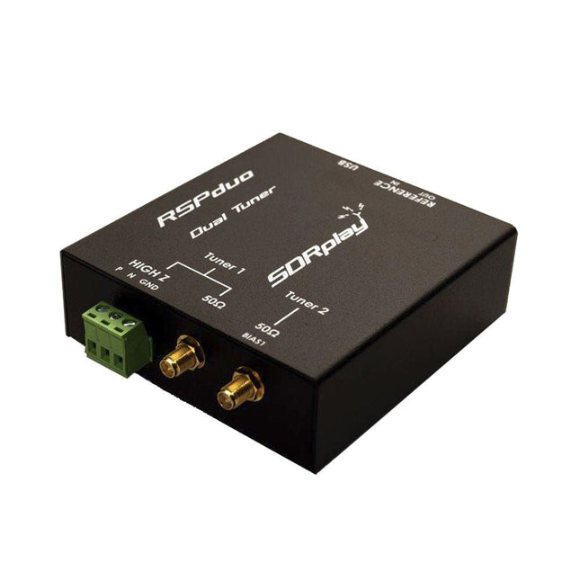
De SDRplay RSPduo is een hoogwaardige 14-bit SDR-ontvanger met dubbele tuner. De tuner is ondergebracht in een hoogwaardige stalen behuizing en kan afzonderlijk werken tussen 1 kHz en 2 GHz met een bandbreedte tot 10 MHz. Beide tuners kunnen tegelijkertijd werken tussen 1 kHz en 2 GHz met een bandbreedte tot 2 MHz per tuner.
Een zeer stabiele referentie en externe klokfuncties maken dit apparaat ideaal voor industriële, wetenschappelijke en educatieve toepassingen.
Kenmerken
Dubbele tuner biedt onafhankelijke dekking van 1 kHz tot 2 GHz met behulp van 2 antennepoorten tegelijk
14-bits ADC-siliciumtechnologie
Tot 10 MHz zichtbare bandbreedte (enkele tunermodus) of 2 slices van 2 MHz spectrum (dubbele tunermodus)
3 softwarematig selecteerbare antennepoorten (2x 50Ω en 1x 1kΩ hoge impedantie gebalanceerde/ongebalanceerde ingang)
Antennepoort met hoge impedantie (1 kHz tot 30 MHz) met selecteerbaar MW-notchfilter en keuze uit 2 voorselectiefilters
Softwarematig selecteerbare AM/FM- en DAB-uitzendband-notchfilters voor de 2 SMA-antennepoorten (1 kHz tot 2 GHz)
Externe klokinvoer en -uitvoer maken eenvoudige synchronisatie met meerdere RSP's of een externe referentieklok mogelijk
Wordt gevoed via de USB-kabel met een eenvoudige type B-aansluiting
11 hoogselectieve, ingebouwde front-end preselectiefilters op beide 2 SMA-antennepoorten
Softwarematig selecteerbare multi-level Low Noise voorversterker
Bias-T voeding voor het voeden van een op de antenne gemonteerde LNA
In een robuuste, zwart gelakte stalen behuizing.
SDRuno – SDR-software van wereldklasse voor Windows
Gedocumenteerde API voor de ontwikkeling van nieuwe apps
Specificaties
Frequentiebereik
1 kHz – 2 GHz
Antenne-aansluiting
SMA
Antenne-impedantie
50 ohm
Stroomverbruik (typisch)
Enkele tunermodus: 180 mA (excl. Bias-T)Dubbele tunermodus: 280 mA (excl. Bias-T)
USB-aansluiting
USB type B
Maximaal ingangsvermogen
+0 dBm Continu+10 dBm korte duur
ADC-samplefrequenties
2-10,66 MSPS
ADC-aantal bits
14 bit 2-6,048 MSPS12 bit 6,048-8,064 MSPS10 bit 8,064-9,216 MSPS8 bit >9,216 MSPS
Bias-T
4,7 V100 mA gegarandeerd
Referentie
Hoge temperatuurstabiliteit (0,5 ppm) 24 MHz TCXOFrequentiefout instelbaar tot 0,01 ppm in het veld
Bedrijfstemperatuurbereik
−10°C tot +60°C
Afmetingen
98 x 94 x 33 mm
Gewicht
315 g
Downloads
Datasheet
Detailed Technical Information
Software
RSPdx-R2 vs RSPduo
RSPdx-R2
RSPduo
Continue dekking van 1 kHz tot 2 GHz
✓
✓
Tot 10 MHz zichtbare bandbreedte
✓
✓
14-bits ADC siliciumtechnologie plus meerdere krachtige ingangsfilters
✓
✓
Softwarematig selecteerbare AM/FM & DAB broadcast band notch filters
✓
✓
4,7 V Bias-T voor voeding van externe antenneversterker
✓
✓
Voedt de USB-kabel met een eenvoudige aansluiting type B
✓
✓
50Ω SMA-antenne-ingang(en) voor werking van 1 kHz tot 2 GHz (softwarematig instelbaar)
2
2
Extra softwarematig selecteerbare Hi-Z ingang voor werking tot 30 MHz
✓
Extra softwarematig selecteerbare 50Ω BNC-ingang voor werking tot 200 MHz
✓
Extra LF/VLF-filter voor onder 500 kHz
✓
24 MHz referentieklokingang (+ uitgang op RSPduo)
✓
✓
Dubbele tuners voor ontvangst op 2 totaal onafhankelijke 2 MHz-bereiken
✓
Dubbele tuners voor diversiteitsontvangst met SDRuno
✓
Robuuste zwartgelakte stalen behuizing
✓
✓
Algemene prestaties onder 2 MHz voor MW en LF
++
+
Meerdere gelijktijdige toepassingen
+
++
Prestaties in uitdagende fading-omstandigheden (*met gebruik van diversiteitsafstemming)
+
*++
De SDRplay RSPdx-R2 is een breedbandige, volledig uitgeruste 14-bit SDR-ontvanger met één tuner die het volledige RF-spectrum van 1 kHz tot 2 GHz bestrijkt, met een spectrumbereik tot 10 MHz. Hij bevat drie antennepoorten, waarvan er twee SMA-connectoren gebruiken en werken over het volledige bereik van 1 kHz tot 2 GHz, en de derde een BNC-connector heeft die werkt tot 200 MHz.
De RSPdx-R2 is een verbeterde versie van de RSPdx met verdere ontwerpverbeteringen voor gebruik bij frequenties lager dan 2 MHz. De RSPdx-R2 is gehuisvest in een stevige stalen behuizing en biedt, naast de functionaliteit van de RSP1B, drie softwarematig selecteerbare antenne-ingangen en een externe klokingang. Hij biedt uitstekende prestaties op HF- en VHF-frequenties tot wel 2 GHz. De RSPdx-R2 ondersteunt ook een "HDR-modus" die geoptimaliseerd is voor de veeleisende radio-ontvangstomstandigheden onder de 2 MHz.
De RSPdx-R2 introduceert, in combinatie met de eigen software van SDRplay, een speciale HDR-modus (High Dynamic Range) voor ontvangst binnen geselecteerde banden onder de 2 MHz. De HDR-modus levert verbeterde intermodulatieprestaties en minder storende signalen voor die uitdagende banden.
Kenmerken
Bestrijkt alle frequenties van 1 kHz via VLF, LF, MW, HF, VHF, UHF en L-band tot 2 GHz, zonder onderbrekingen
Ontvang, bewaak en neem tot 10 MHz spectrum tegelijk op
Aanzienlijk verbeterde ruisprestaties onder 1 MHz (d.w.z. voor sommige MF, LF en lager)
Verbeterd dynamisch bereik onder 2 MHz, zowel in tunermodus als HDR-modus
HDR-modus onder 2 MHz biedt voordelen op het gebied van algemeen dynamisch bereik en selectiviteit
Softwarematig selecteerbare keuze uit 3 antennepoorten
Externe klokingang voor synchronisatiedoeleinden, of aansluiting op GPS-referentieklok voor extra frequentienauwkeurigheid
Uitstekend dynamisch bereik voor uitdagende ontvangstomstandigheden
Gratis gebruik van Windows-gebaseerde SDRuno-software (raadpleeg de website voor ondersteunde versies)
Gratis gebruik van SDRconnect SDR- en serversoftware voor Windows, MacOS en Linux (raadpleeg de website voor ondersteunde versies)
Ondersteuning voor multiplatform drivers en API's, waaronder Windows, Linux, Mac en Raspberry Pi 4/5
Sterk en groeiend softwareondersteuningsnetwerk
Gekalibreerde S-meter/RF-vermogens- en signaal-ruisverhoudingsmeting met SDRuno (inclusief datalogging naar .CSV-bestanden)
Gedocumenteerde API beschikbaar voor demodulator- of applicatieontwikkeling op meerdere platforms
Toepassingen (Amateur)
Luisteren naar kortegolfradio
Uitzending DX (AM/FM/TV)
Panadaptor
Vliegtuigen (ADS-B en ATC)
Slow Scan TV
Monitoring van multi-amateurbanden
WSPR & digitale modi
Weerfax (HF en satelliet)
Satellietmonitoring
Geostationaire omgevingssatellieten
Trunked radio
Monitoring van nutsbedrijven en hulpdiensten
Snelle en effectieve antennevergelijking
Toepassingen (Industrieel)
Spectrum Analyser
Bewaking
Draadloze microfoonbewaking
RF-meting
IoT-ontvangerketen
Signaalregistratie
RFI/EMC-detectie
Bewaking van de uitzendintegriteit
Spectrumbewaking
Vermogensmeting
Toepassingen (Educatief/Wetenschappelijk)
Onderwijs
Ontwerp van ontvangers
Radioastronomie
Passieve radar
Ionosonde
Spectrumanalysator
Ontvanger voor IoT-sensorprojecten
Antenneonderzoek
Specificaties
Frequentiebereik
1 kHz – 2 GHz
Antenne-aansluiting
SMA
Antenne-impedantie
50 ohm
Stroomverbruik (typisch)
190 mA bij >60 MHz (excl. Bias-T)120 mA bij <60 MHz (excl. Bias-T)
USB-aansluiting
USB-B
Maximaal ingangsvermogen
+0 dBm Continu+10 dBm korte duur
ADC-samplefrequenties
2-10,66 MSPS
ADC-aantal bits
14 bit 2-6,048 MSPS12 bit 6,048-8,064 MSPS10 bit 8,064-9,216 MSPS8 bit >9,216 MSPS
Bias-T
4,7 V100 mA gegarandeerd
Referentie
0,5 ppm 24 MHz TCXOFrequentiefout trimbaar tot 0,01 ppm in het veld
Bedrijfstemperatuur
−10˚C tot +60˚C
Afmetingen
113 x 94 x 35 mm
Gewicht
315 g
Downloads
Datasheet
Software
RSPdx-R2 vs RSPduo
RSPdx-R2
RSPduo
Continue dekking van 1 kHz tot 2 GHz
✓
✓
Tot 10 MHz zichtbare bandbreedte
✓
✓
14-bits ADC siliciumtechnologie plus meerdere krachtige ingangsfilters
✓
✓
Softwarematig selecteerbare AM/FM & DAB broadcast band notch filters
✓
✓
4,7 V Bias-T voor voeding van externe antenneversterker
✓
✓
Voedt de USB-kabel met een eenvoudige aansluiting type B
✓
✓
50Ω SMA-antenne-ingang(en) voor werking van 1 kHz tot 2 GHz (softwarematig instelbaar)
2
2
Extra softwarematig selecteerbare Hi-Z ingang voor werking tot 30 MHz
✓
Extra softwarematig selecteerbare 50Ω BNC-ingang voor werking tot 200 MHz
✓
Extra LF/VLF-filter voor onder 500 kHz
✓
24 MHz referentieklokingang (+ uitgang op RSPduo)
✓
✓
Dubbele tuners voor ontvangst op 2 totaal onafhankelijke 2 MHz-bereiken
✓
Dubbele tuners voor diversiteitsontvangst met SDRuno
✓
Robuuste zwartgelakte stalen behuizing
✓
✓
Algemene prestaties onder 2 MHz voor MW en LF
++
+
Meerdere gelijktijdige toepassingen
+
++
Prestaties in uitdagende fading-omstandigheden (*met gebruik van diversiteitsafstemming)
+
*++
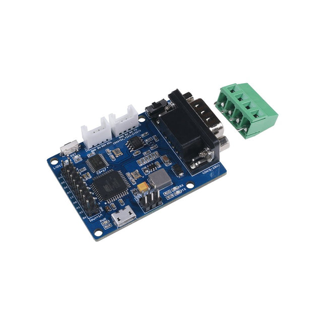
Features Volgt CAN V2.0B tot 1 Mb/s Industriële standaard 9 pins sub-D connector OBD-II en CAN standaard pinout selecteerbaar. Verwisselbare chip select pin Verwisselbare CS pin voor TF-kaartslot Verwisselbare INT pin Schroef terminal die gemakkelijk aan te sluiten CAN_H en CAN_L Arduino Uno pin headers Micro SD kaarthouder 2 Grove connectoren (I2C en UART) SPI-interface tot 10 MHz Standaard (11 bit) en uitgebreide (29 bit) data en remote frames Twee ontvangstbuffers met geprioriteerde berichtopslag
De Seeed Studio CANBed – Arduino CAN-BUS Development Kit integreert een ATmega32U4-microcontroller, waardoor een extern Arduino-bord overbodig is. Het combineert een MCP2515 CAN-buscontroller en een MCP2551 CAN-bustransceiver op één bord en biedt zo een compacte en betrouwbare CAN-communicatieoplossing.
Kenmerken
ATmega32U4 met Arduino Leonardo bootloader op het bord
MCP2515 CAN Bus controller en MCP2551 CAN Bus transceiver
OBD-II en CAN standaard pinout selecteerbaar op de sub-D connector
Compatibel met Arduino IDE
Parameter
Waarde
MCU
ATmega32U4 (met Arduino Leonardo bootloader)
Kloksnelheid
16 MHz
Flashgeheugen
32 KB
SRAM
2,5 KB
EEPROM
1 KB
Bedrijfsspanning (CAN-BUS)
9 V - 28 V
Bedrijfsspanning (MicroUSB)
5 V
Invoer Interface
sub-D
Inbegrepen
CANBed PCBA
sub-D connector
4PIN aansluiting
2x 4PIN 2.0 Aansluiting
1x 9x2 2.54-kopje
1x 3x2 2.54-kopje
De starterkit voor Jetson Nano is een van de beste kits voor beginners om aan de slag te gaan met Jetson Nano. Deze kit bevat een MicroSD-kaart van 32 GB, een adapter van 20 W, een 2-pins jumper, een camera en een micro-USB-kabel.
Kenmerken
32 GB krachtige MicroSD-kaart
5 V/4 A voeding met 2,1 mm DC-cilinderconnector
2-pins jumper
Raspberry Pi-cameramodule V2
Micro-B naar Type-A USB-kabel met DATA ingeschakeld
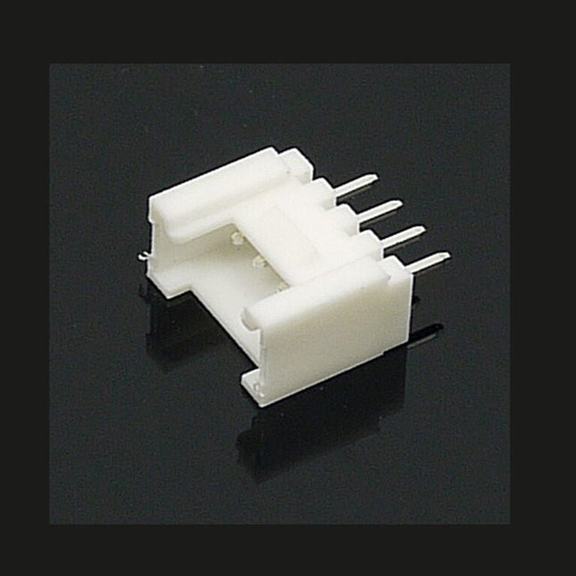
The universal 4 Pin connector is a white 4-pin buckled connector used on Stem, Twigs and Grove cables. The pin spacing is 2 mm. There are 10 connectors per bag. They can be used in DIY projects.
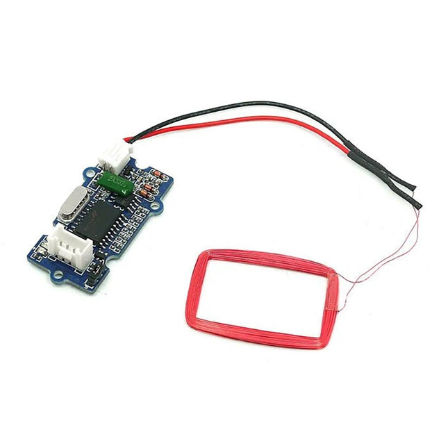
Features Selectable output format: Uart or Wiegand. 4Pins Electronic Brick Interface High Sensitivity Specifications Dimensions: 44 mm x 24 mm x9.6 mm Weight: 15 g Battery: Exclude Voltage: 4.75 V - 5.25 V Working Frequency: 125 kHz Sensing Distance(Max): 70 mm TTL Output: 9600 baud rate, 8 data bits, 1 stop bit, and no verify bit Wiegand Output: 26 bits Wiegand format, 1 even verify bit, 24 data bits, and 1 odd verify bit
Grove 3-Axis Digitale Versnellingsmeter (LIS3DHTR) is een goedkope 3-Axis versnellingsmeter in een bundel van Grove producten. Het is gebaseerd op de LIS3DHTR chip die meerdere bereiken en interfaces selectie biedt. Het is niet te geloven dat zo'n kleine 3 assige versnellingsopnemer I²C, SPI en ADC GPIO interfaces kan ondersteunen, wat betekent dat u elke manier kunt kiezen om verbinding te maken met uw ontwikkelbord. Bovendien kan deze versnellingsmeter ook de omringende temperatuur monitoren om de daardoor veroorzaakte fout af te stellen. Features Metingsbereik: ±2g, ±4g, ±8g, ±16g, selectie van meerdere bereiken. Meervoudige interfaces optie: Grove I²C interface, SPI interface, ADC interface. Temperatuur instelbaar: in staat om aan te passen en af te stemmen de fout veroorzaakt door temperatuur. 3/5V voeding Specificaties Voeding 3/5V Interfaces IC/SPI/GPIO ADC I²C adres Standaard 0x19, kan worden gewijzigd in 0x18 wanneer SDO Pin wordt verbonden met GND ADC GPIO stroomingang 0-3.3V Onderbreking Een onderbrekingsspeld gereserveerd SPI-Modus instellen Sluit de CS-Pin aan op GND Inclusief 1x Grove 3-Axis Digitale Versnellingsmeter (LIS3DHTR) 1x Grove kabel Downloads LIS3DHTR Datasheet Hardwareschema Arduino-bibliotheek
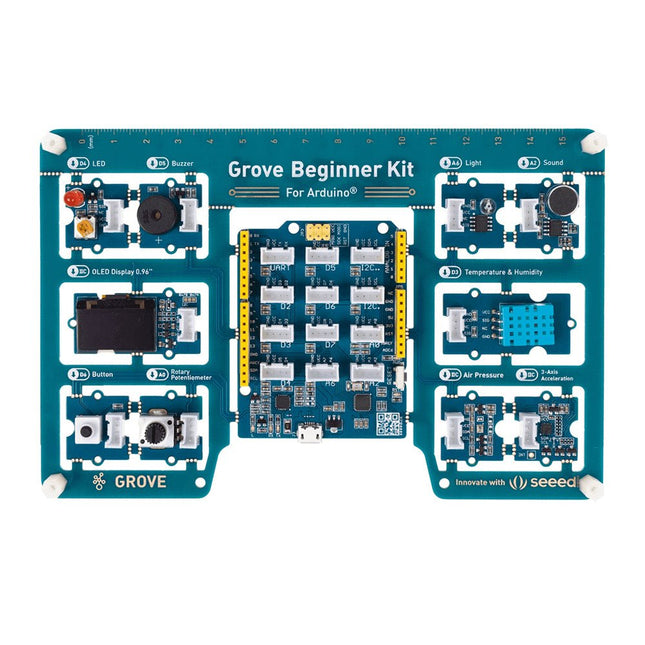
Unlike most kits, the Grove Beginner Kit for Arduino is an all-in-one kit, no breadboard, no soldering, even no wiring is needed. The kit is powered by one Arduino compatible Board (Seeeduino Lotus) together with 10 additional Grove Arduino sensors all in one piece of the board. All the modules have been connected to the Seeeduino(Microcontroller) through the PCB stamp holes so no Grove cables are needed to connect. This is perfect for educational fields where frustrating wiring and soldering are no longer needed. Of course, you can also take the modules out and use Grove cables to connect the modules. You can build any Arduino project you like with this Grove Beginner Kit For Arduino. Included in Kit: 1 x Grove Beginner Kit For Arduino Board 1 x Micro USB Cable 6 x Grove Cables Included onboard: 1 x Grove - LED 1 x Grove - Buzzer 1 x Grove - OLED Display 0.96' 1 x Grove - Button 1 x Grove - Rotary Potentiometer 1 x Grove - Light 1 x Grove - Sound 1 x Grove - Temperature & Humidity Sensor 1 x Grove - Air Pressure Sensor 1 x Grove - 3-Axis Accelerator 1 x Seeeduino Lotus
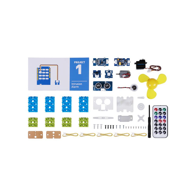
Toepassingen
Geschikt voor Arduino beginners
Geschikt voor infraroodsturing en bewegingsdetectie
Geschikt om aan de slag te gaan met open-source hardware en Arduino codering
Deel Lijst
1x Grove - Waterverstuiving
1x Grove - Mini Ventilator
1x Grove - Servo
1x Grove - Ultrasone Afstandssensor
1x Grove - Infrarood Ontvanger
1x Grove - Mini PIR Bewegingssensor
1x Grove - Groene Wikkel
1x Grove - Blauwe Wikkel
5x Grove kabel
1x Infrarood Remote Control Key
1x Ultrasone sensor beugelset
1x motorbeugelset
1x Servo Basis
Let op: Dit is een uitbreidingsset voor de Seeed Studio Grove Beginner Kit voor Arduino.
This Grove CAN-BUS Module based on GD32E103 adopts a brand-new design, uses the cost-effective and high-performance GD32E103 microcontroller as the main control and cooperates with a firmware we wrote to complete the function of the serial port to CAN FD. Features
Support CAN communication: Implements CAN FD at up to 5 Mb/s
Easy to program: Support AT command which enables simple serial port programming
Grove ecosystem: 20 x 40 x 10 mm small size, 4-pin Grove connector to plug and play, Arduino compatible This Grove CAN-BUS Module supports CAN FD(CAN with Flexible Data-Rate) communication, which is an extension to the original CAN protocol as specified in ISO 11898-1 that responds to increased bandwidth requirements in automotive networks. In CAN FD, the data rate (i.e. number of bits transmitted per second) is increased to be 5 times faster than the classic CAN (5 Mbit/s for the data payload only, the arbitration bit rate is still limited to 1Mbit/s for compatibility). It supports AT command which enables simple serial port programming. This Grove CAN-BUS Module is based on GD32E103 with a frequency up to 120 MHz. It has a flash size from 64 KB to 128 KB and an SRAM size from 20 KB to 32 KB. Applications Car hacking: allows different parts of the vehicle to talk to each other, including the engine, the transmission, and the brakes. Windows, doors, and mirror adjustment. 3D Printers Building automation Lighting control systems Medical instruments and equipment Specifications MCU GD32E103 UART baud rate Up to 115200 (default 9600) CAN FD baud rate Up to 5 Mb/s Indicator TX and RX led Working voltage 3.3 V Grove connector 4-pin Grove connector to plug and play Size 20 x 40 x 10 mm Downloads Datasheet GitHub
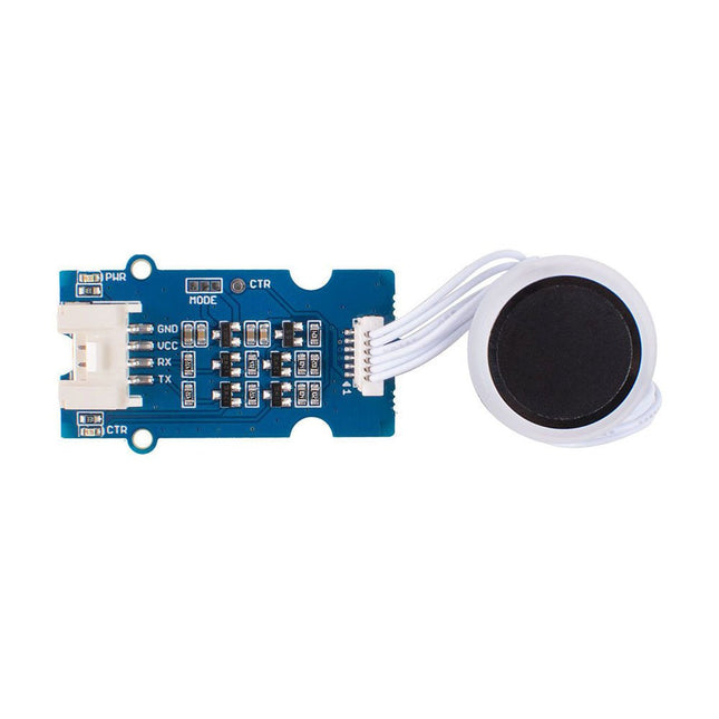
De Grove Capacitieve Vingerafdrukscanner/Sensor is gebaseerd op de KCT203 Halfgeleider vingerafdrukherkenning module, met inbegrip van een krachtige MCU, een verticale RF push-type vingerafdruksensor, en een touch sensing device.Deze module biedt vele voordelen, zoals kleine afmetingen, kleine vingerafdruksjabloon, laag stroomverbruik, hoge betrouwbaarheid, snelle vingerafdrukherkenning, enz. Bovendien is het vermeldenswaard dat er een mooi RGB-lampje rond deze module zit om aan te geven of de vingerafdrukherkenning geslaagd is.Het systeem is uitgerust met een krachtig vingerafdrukalgoritme, en de zelflerende functie is opmerkelijk. Na elke succesvolle vingerafdruk herkenning, kan de nieuwste uitdaging kenmerk waarden worden geïntegreerd in de vingerafdruk database om voortdurend verbeteren van de vingerafdruk kenmerken, waardoor de ervaring beter.Toepassingen
Vingerafdruk slot apparaten: deursloten, kluizen, stuurwiel sloten, hangsloten, pistool sloten, etc.
Vingerafdruk sign-in, toegangscontrole systeem
Specificaties
CPU
GD32
Opslag vingerafdruksjablonen
Max. 100
Connector
Grove UART
Sensor Resolutie
508 DPI
Sensor Pixel
160x160
Het percentage foute weigeringen
<1%
Het percentage onterechte aanvaardingen
<0.005%
Reactietijd overeenkomst (1:N-modus)
<350ms
Reactietijd wedstrijd (1:1-modus)
<7ms
Sensor grootte
?14.9mm
Kadergrootte
? 19mm
Power Consumption
Volledige snelheid: ?40 mA; Slaap: ?12 uA
Bedrijfsspanning
3,3 V / 5 V
Bedrijfstemperatuur
-20 ~ 70 ?
ESD-bescherming
Niet-contact 15 KV, contact 8 KV
Inbegrepen
1x KCT203 halfgeleider vingerafdrukherkenningsmodule
1x Sensor kabel
1x Grove kabel
1x Grove driver bord
Documentatie
Grove Capacitieve Vingerafdrukscanner/Sensor eagle bestand
Grove Capacitieve Vingerafdrukscanner/Sensor code
Wiki
De Grove DHT11 Temperatuur & Vochtigheid Sensor is een hoogwaardige, betaalbare digitale temperatuur & vochtigheid sensor gebaseerd op de DHT11 module.Het is de meest voorkomende temperatuur en vochtigheid module voor Arduino en Raspberry Pi. Het wordt op grote schaal verkozen door hardware enthousiastelingen vanwege de vele voordelen, zoals een laag stroomverbruik en een uitstekende stabiliteit op lange termijn. Relatief hoge meetnauwkeurigheid kan worden verkregen tegen een zeer lage kostprijs.Het single-bus digitale signaal wordt uitgevoerd via de ingebouwde ADC, waardoor de I/O-bronnen van de besturingskaart worden gespaard.Features
Afmetingen: 40 x 20 x 8 mm
Gewicht: 10 g
Batterij: Exclusief
Ingangsspanning: 3,3 V & 5 V
Stroomsterkte: 1.3 mA- 2.1 mA
Vochtigheidsbereik: 5% - 95% RH
Bepaling Temperatuurbereik: -20 ? - 60 ?
Features Grove Compatibel 3.5mm aansluiting 6 wegwerp oppervlakte elektroden Voedingsspanning: 3,3V-5V 1000mm kabelkabels Geen extra stroomvoorziening Specificaties Afmetingen: 140 mm x 100 mm x 30 mm Gewicht: 45 g Batterij: Exclusief Onderdelenlijst 1 x Grove - EMG Detector 1 x Grove kabel 6 x eenmalige elektrode 1 x DC jack naar knop connector kabel 1000mm
Features Ondersteunt NMEA en U-Blox 6 protocollen. Laag stroomverbruik Baudrates configureerbaar Grove UART-interface Specificaties Afmetingen 40 mm x 20 mm x 13 mm Update snelheid 1 Hz, max 10 Hz Baud Rate 9.600 - 115.200 Invoer Voltage 3,3 V / 5 V Navigatiegevoeligheid -160dBm Voedingsvereisten 3.3/5V Aantal Kanalen 22 tracking, 66 kanalen Tijd tot eerste start Koude start: 13sWarme start: 1-2swarme start: < 1s Antennels Antenne inbegrepen Nauwkeurigheid 2,5m GPS Horizontale Positie Nauwkeurigheid
Features Integrated Cold-Junction Compensation Supported Types (designated by NIST ITS-90): Type K, J, T, N, S, E, B and R Four Programmable Temperature Alert Outputs: Monitor Hot- or Cold-Junction Temperatures Detect rising or falling temperatures Up to 255°C of Programmable Hysteresis Programmable Digital Filter for Temperature Low Power Dimensions: 20 mm x 40 mm x 18 mm Weight: 18 g Application Petrochemical Thermal Management Hand-Held Measurement Equipment Industrial Equipment Thermal Management Ovens Industrial Engine Thermal Monitor Temperature Detection Racks Downloads Eagle Files Github library Datasheet
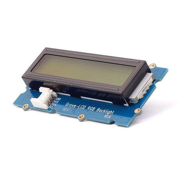
De traditionele 16x2 LCD heeft tot 10 I/O pinnen nodig voor de weergave, en de 16x2 LCD met RGB achtergrondverlichting heeft nog eens 3 extra pinnen nodig om de kleur van de achtergrondverlichting te regelen. Dit neemt veel I/O-pinnen in beslag op de hoofdbesturingskaart, vooral voor ontwikkelingskaarten met minder I/O-bronnen, zoals Arduino en Raspberry Pi. Met behulp van de Grove I2C connector zijn slechts 2 signaalpennen en 2 voedingspennen nodig. Je hoeft niet eens zorgen te maken over hoe deze pinnen aan te sluiten. Gewoon aansluiten op de I2C interface op Seeeduino of Arduino/Raspberry Pi+baseshield via de Grove kabel. Geen ingewikkelde bedrading, geen solderen, geen zorgen te maken over het verbranden van de LCD veroorzaakt door de verkeerde stroombegrenzende weerstand. Easy peasy. Specificaties Afmetingen: 83 mm x 44 mm x 13 mm Gewicht: 42 g Batterij: Exclusief Ingangsspanning: 5 V
Grove LED Bar is comprised of a 10 segment LED gauge bar and an MY9221 LED controlling chip. It can be used as a indicator for remaining battery life, voltage, water level, music volume or other values that require a gradient display.There are 10 LED bars in the LED bar graph: one red, one yellow, one light green, and the rest green. Demo code is available to get you up and running quickly. It lights up the LEDs sequentially from red to green, so the entire bar graph is lit up in the end. Want to go further? Go ahead and code your own effect!Features
Each LED segment can be controlled individually via code
Grove module
Plug-and-play
Can be cascaded for a larger display
Flexible power option, supports 3-5.5 DC
Available demo code
Dimensions: 40 x 20 x 18 mm
Included
1x Grove LED Bar v2.0
1x Grove Cable
Downloads
Grove LED Bar Eagle File
Grove LED Bar Library
MY9221 Datasheet
Suli-compatible Library
GitHub repository for LED Bar
10 Segment LED Gauge Bar