This is a high-performance cooling solution designed to effectively dissipate heat and ensure optimal operating temperatures for the Raspberry Pi. It is an essential accessory for users who want to enhance the performance and longevity of their Raspberry Pi device.
The compact design of the Water cooling kit for Raspberry Pi 5 allows it to be seamlessly installed on the top and bottom of the Raspberry Pi 5, ensuring efficient heat transfer and perfectly protecting the bottom of the Raspberry Pi. Its simple installation process eliminates the need for complex wiring or additional tools, making it friendly to both beginners and experienced Raspberry Pi enthusiasts.
With its powerful cooling performance, the water cooling kit for Raspberry Pi 5 for effectively dissipates heat generated by the Raspberry Pi during intensive tasks or prolonged usage. This helps prevent overheating and ensures stable performance. Efficient water-cooled cooling will allow you to connect multiple Raspberry Pi boards to a set of cooling devices. When using Raspberry Pi in a cluster, you can use a set of water-cooled devices to effectively cool multiple Raspberry Pi boards.
Features
Made for Raspberry Pi: Specially designed for Raspberry Pi 5, 1:1 mold opening, covering all heat sources, including CPU, Wi-Fi, power chip, and eMMC.
Cooling Performance: Effectively dissipates the heat generated by the Raspberry Pi, ensuring optimal operating temperatures and preventing overheating.
Easy to Use: The integrated design of the water pump and cooling fan is convenient for users to install.
RGB Color Lighting: RGB-colored lights are installed at the fan and water pump locations.
Included
1x Water cooling kit
1x Water cooling radiator
1x Black heatsink
2x Silicone hose
1x 12 V/2 A power adapter (US)
4x Hexagonal screw M2.5x10
1x L-key hex wrench
Features
Internal LNA amplifier and selectable attenuator
Low frequency support from 50KHz covering LF, MF, HF, VHF and UHF up to 960Mhz
New HELP and SET buttons to improve user interface and configuration selection with 2-clicks
Wide band coverage to all popular sub-1Ghz bands, including FM, TV and DTV, ISM, RFID, GSM, etc.
Ideal choice for HAM bands from 160meters to 33cm
Pocket size and light weight
Solid metal case
Spectrum Analyzer mode with Peak Max and Hold, Normal, Overwrite and Averaging modes
High capacity internal Lithium battery for 20hs+ of continuous run, rechargeable by USB
Multi-platform Windows/Linux/MacOS Open Source software and API libraries
Can be extended with internal Expansion Modules for additional band and functionality
Specifications
Frequency band: 0.05 MHz - 960 MHz
Frequency span: 0.1 MHz - 960 MHz
Internal selectable LNA 25 dB gain
Internal selectable Attenuator 30 dB
Graphics LCD 128 x 64 pixels, great visibility outdoors
Support included for Windows, Linux and MacOS X
Backlight for great visibility indoor
Internal Lithium Ion 1800mA/h rechargeable battery
Standard SMA 50 Ω connector
Wideband 144/433MHz dual band telescopic antenna included
UHF 400-900 MHz rubber duck articulated antenna included
Amplitude resolution: 0.5dBm
Dynamic range: -125 dBm to 10 dBm
Absolute Max input power: +30dBm
Average noise level (typical LNA): -125 dBm
Frequency stability and accuracy (typical): +-10 ppm
Amplitude stability and accuracy (typical): +-2d Bm
Frequency resolution: 1kHz
Resolution bandwidth (RBW): automatic 2.6 kHz to 600 kHz
Included
1x RF Explorer WSUB1G+ Spectrum Analyzer
1x Mini USB cable
1x Dual band 144/430MHz Telescopic antenna
1x UHF 400-900Mhz antenna
1x EVA case
You can use RF Explorer 3G Combo equally well outdoor and indoor, and you can also connect it to a PC for extra functionality using standard mini-USB 2.0 connector.
This model includes a WSUB1G baseline unit plus an RFEMWSUB3G Expansion Module conveniently assembled and tested. It comes with two SMA connectors and two antennas,a dual band telescopic 144 / 430 MHz antenna for all Sub-GHz frequencies and a whip helical antenna for 2.4 GHz band. Additional, specific band antennas may be needed to cover efficiently some of the frequencies supported.
The combination of these two models offer the wide band coverage of the WSUB3G module, together with the highest sensitivity and quick response of the WSUB1G model for the popular sub-1GHz frequencies.
Features
Pocket size and light weight
Solid aluminum metal case
Includes a transport EVA carry case for RF Explorer
Spectrum Analyzer mode with Peak Max and Hold, Normal, Overwrite and Averaging modes
Lifetime free firmware upgrades available, open to community requested features
High capacity Lipo for 16 hours+ of continuous run, rechargeable by USB
Windows PC client Open Source
Can be extended with internal Expansion Modules for additional band and functionality
Wide band coverage to all popular RF frequencies, starting at 15 MHz and going up to 2.7 GHz. This includes very interesting frequency areas such as 2 m HAM radio, all VHF and UHF, FM radio, GPS, WiFi and WiMax, Bluetooth, etc.
Firmware: RF Explorer 3G Combo is delivered with upgraded firmware v1.09. Note some of the features and operation accuracy will be improved in upcoming free firmware revisions.
Specifications
Battery
Lithium Cells / Batteries contained in equipment UN3481 - PI967
Frequency band
15-2700 MHz
Frequency span
112 KHz - 600 MHz
Graphics LCD
128 x 64 pixels, great visibility outdoors
PC Windows client
supports Windows XP/Vista/Win7 both 32 and 64bits
Backlight
for great indoor visibility
2 standard SMA 50 ohms connector,
one for Sub-GHz wideband Nagoya NA-773 telescopic antenna included and another 2.4 GHz one for 15-2700 MHz band with helical antenna included.
Amplitude resolution
0.5 dBm
Dynamic range
Left SMA port (WSUB1G)
-115 dBm to 0 dBm
Right SMA port (WSUB3G)
-110 dBm to -10 dBm
Absolute Max input power
Left SMA port (WSUB1G)
+5 dBm
Right SMA port (WSUB3G)
+30 dBm
Average noise level (typical)
-110 dBm
Frequency stability and accuracy (typical)
+-10 ppm
Amplitude stability and accuracy (typical)
+-6 dBm
Frequency resolution
1 KHz
Resolution bandwidth (RBW)
automatic 3 KHz to 600 KHz
Weight
185 g
Size
113 x 70 x 25 mm
Included
RF Explorer 3G Combo
Nagoya NA-773 wideband telescopic antenna
2.4 GHz band antenna
EVA Case
Documentation
For more info and to get started with your RF Explorer, visit the start page.
For questions and support, please visit https://support.rf-explorer.com
Het Elektor Arduino Nano MCCAB Training Board bevat alle componenten (incl. Arduino Nano) die nodig zijn voor de oefeningen, zoals LED’s, schakelaars, drukknoppen, buzzer enz. Ook externe sensoren, motoren of modules kunnen worden gecheckt of bestuurd met dit microcontroller-trainingssysteem.
Specificaties (Arduino Nano Training Board MCCAB)
Voeding
Via de USB-aansluiting van de aangesloten pc of een externe voeding (niet inbegrepen)
Spanning
+5 Vcc
Ingangsspanning
Alle ingangen
0 V tot +5 V
VX1 en VX2
+8 V tot +12 V (alleen bij gebruik van een externe voeding)
Hardware
LCD
2x16 karakters
Potentiometer P1 & P2
JP3: Selectie van de werkspanning van P1 & P2
Verdelers
SV4: Verdeler voor de werkspanningenSV5, SV6: Verdelers voor de in-/uitgangen van de microcontroller
Schakelaars en knoppen
RESET knop op de Arduino Nano module; 6x drukknop schakelaars K1 ... K6; 6x Schuifschakelaars S1 ... S6; JP2: Jumper van de schakelaars met de ingangen van de microcontroller
Buzzer
Piezo buzzer ‘Buzzer1’ met jumper op JP6
Indicator LED’s
11 x LED: Status indicator voor de ingangen/uitgangen LED L op de Arduino Nano module, aangesloten op GPIO D13 JP6; Aansluiting van LED's LD10 ... LD20 met GPIO's D2 ... D12
Seriële interfacesSPI & I²C
JP4: Selectie van het signaal op pin X van de SPI-connector SV12 SV9 naar SV12: SPI-interface (3,3 V/5 V) of I²C-interface
Uitgangen voor externe apparaten
SV1, SV7: Geschakelde uitgang (maximaal +24 V/160 mA, extern aangesloten) SV2: 2x13 pinnen voor aansluiting van externe modules
3x3 LED matrix(9 rode LED's)
SV3: Kolommen van de 3x3 LED matrix (uitgangen D6 ... D8) JP1: Verbinding van de rijen met de GPIO's D3 ... D5
Software
MCCABLib library
Controle van hardware componenten (schakelaars, knoppen, LED's, 3x3 LED matrix, buzzer) op het MCCAB Training Board
Werktemperatuur
Tot +40 °C
Afmetingen
100 x 100 x 20 mm
Specificaties (Arduino Nano)
Microcontroller
ATmega328P
Architectuur
AVR
Spanning
5 V
Flash memory
32 KB, waarvan 2 KB gebruikt door de bootloader
SRAM
2 KB
Kloksnelheid
16 MHz
Analoge IN Pinnen
8
EEPROM
1 KB
DC stroom per I/O-pin
40 mA op één I/O-pin, totaal maximaal 200 mA op alle pinnen samen
Ingangsspanning
7-12 V
Digitale I/O-pinnen
22 (waarvan 6 PWM)
PWM Uitgangen
6
Stroomverbruik
19 mA
Afmetingen
18 x 45 mm
Gewicht
7 g
Inbegrepen
1x Elektor Arduino Nano Training Board MCCAB
1x Arduino Nano
Beheers digitale elektronica – op een praktische manier!
Deze bundel bevat het boek Learning Digital Electronics met meer dan 20 praktische projecten in logica- en schakelingontwerp, evenals een 100-delige starterkit – zodat u meteen aan de slag kunt met het bouwen van logische schakelingen, tellers, displays en meer.
Learning Digital Electronics (Boek)
Dit boek is een praktische gids voor digitale elektronica en behandelt de essentiële componenten van moderne digitale systemen: getallensystemen, logische poorten, Booleaanse algebra, combinatorische en sequentiële logica, en meer.
Via meer dan 20 gestructureerde projecten ontwerp en bouw je digitale systemen met behulp van echte componenten zoals logische poorten, multiplexers, decoders, flipflops, tellers en schuifregisters. De projecten variëren van eenvoudige LED-logicacircuits tot digitale sloten, displaysystemen, verkeerslichtcontrollers en timinggebaseerde ontwerpen.
Geselecteerde projecten introduceren het gebruik van tools zoals CircuitVerse voor circuitsimulatie, terwijl verschillende ontwerpen gebruikmaken van logische componenten uit de 74HC-serie, die veel worden gebruikt bij het maken van digitale hardwareprototyping.
Binnenin vindt u:
Duidelijke uitleg over getallensystemen en binaire rekenkunde
Fundamentele principes van logische poorten en universele poortimplementaties
Stapsgewijze projecten met flipflops, tellers en registers
Real-world ontwerp met 74HC-serie logische chips
Technieken voor het ontwerpen van combinatorische en sequentiële systemen
Dit boek hanteert een ontwerpgerichte, toepassingsgerichte benadering van digitale elektronica – opgebouwd rond werkende circuits, geteste logica en praktische experimenten.
Learning Digital Electronics (Kit)
Deze kit is speciaal ontwikkeld als aanvulling op het boek "Learning Digital Electronics". Omdat alle benodigde componenten zijn inbegrepen, kunt u elk praktisch project in het boek direct uitvoeren.
Inhoud van de kit
2x 74HC08 EN-poortchip
2x 74HC00 NAND-poortchip
1x 74HC86 XOR-poortchip
1x 555 timerchip
1x 74HC161 tellerchip
1x 74HC164 schuifregister
1x CD4511 7-segments decoder
1x CD4027 JK flipflop
1x BC337 NPN-transistor
1x KPS-5161 7-segments gemeenschappelijke-kathodedisplay
1x lichtgevoelige weerstand (LDR)
4x 10 KΩ-weerstanden
8x 1 KΩ weerstand
2x 47 KΩ-weerstanden
1x 100 KΩ weerstand
4x 2,7 KΩ-weerstanden
1x 5,6 KΩ weerstand
1x 150 KΩ weerstand
1x 10 μF condensator
2x 0,01 μF condensator
2x 100 nF condensator
8x Kleine rode LED
1x Kleine groene LED
1x Kleine oranje LED
4x Drukknopschakelaars
1x Actieve zoemer
1x Batterijhouder voor 3x AA-batterijen (batterijen niet inbegrepen)
1x Breadboard
40x Male-to-male jumperdraden (lengte: 200 mm)
With 20+ Practical Projects in Logic and Circuit Design
This book is a practical guide to digital electronics, covering the essential components of modern digital systems: number systems, logic gates, Boolean algebra, combinational and sequential logic, and more.
Through more than 20 structured projects, you’ll design and build digital systems using real-world components such as logic gates, multiplexers, decoders, flip-flops, counters, and shift registers. The projects range from basic LED logic circuits to digital locks, display systems, traffic light controllers, and timing-based designs.
Selected projects introduce the use of tools such as CircuitVerse for circuit simulation, while several designs make use of 74HC-series logic devices, commonly used in digital hardware prototyping.
Inside, you’ll find:
Clear coverage of number systems and binary arithmetic
Logic gate fundamentals and universal gate implementations
Step-by-step projects using flip-flops, counters, and registers
Real-world design with 74HC-series logic chips
Techniques for designing combinational and sequential systems
This book takes a design-first, application-driven approach to digital electronics—built around working circuits, tested logic, and hands-on experimentation.
Get Cracking with the Arduino Nano V3, Nano Every, and Nano 33 IoT
The seven chapters in this book serve as the first step for novices and microcontroller enthusiasts wishing to make a head start in Arduino programming. The first chapter introduces the Arduino platform, ecosystem, and existing varieties of Arduino Nano boards. It also teaches how to install various tools needed to get started with Arduino Programming. The second chapter kicks off with electronic circuit building and programming around your Arduino. The third chapter explores various buses and analog inputs. In the fourth chapter, you get acquainted with the concept of pulse width modulation (PWM) and working with unipolar stepper motors.
In the fifth chapter, you are sure to learn about creating beautiful graphics and basic but useful animation with the aid of an external display. The sixth chapter introduces the readers to the concept of I/O devices such as sensors and the piezo buzzer, exploring their methods of interfacing and programming with the Arduino Nano. The last chapter explores another member of Arduino Nano family, Arduino Nano 33 IoT with its highly interesting capabilities. This chapter employs and deepens many concepts learned from previous chapters to create interesting applications for the vast world of the Internet of Things.
The entire book follows a step-by-step approach to explain concepts and the operation of things. Each concept is invariably followed by a to-the-point circuit diagram and code examples. Next come detailed explanations of the syntax and the logic used. By closely following the concepts, you will become comfortable with circuit building, Arduino programming, the workings of the code examples, and the circuit diagrams presented. The book also has plenty of references to external resources wherever needed.
An archive file (.zip) comprising the software examples and Fritzing-style circuit diagrams discussed in the book may be downloaded free of charge below.
This book is about teaching the Python programming language using the Raspberry Pi 4 computer. The book makes an introduction to Raspberry Pi 4 and then teaches Python with the topics: variables, strings, arrays, matrices, tuples, lists, dictionaries, user functions, flow of control, printing, keyboard input, graphics, GUI, object oriented programming and many more topics.
The book is aimed for beginners, students, practising engineers, hobbyists, and for anyone else who may want to learn to program in Python.
The book includes many example programs and case studies. All the example programs and case studies have been tested fully by the author and are all working. The example programs aim to teach the various programming concepts of Python. The case studies cover the use of Python in the analysis and design of electronic circuits. Some of the case study topics are:
Resistor colour code identification
Resistive potential divider circuits
Resistive attenuator design
Zener diode voltage regulator design
RC and RLC transient circuits
Circuit frequency response
Saving data on external memory stick
Mesh and node circuit analysis using matrices
Resonance in RLC circuits
Transistor Biasing analysis
Transistor amplifier design
Design of active filters
Interfacing hardware with GPIO, I²C and SPI
Using Wi-Fi with Python and TCP/IP and UDP programs
Using Bluetooth from Python
Full program listings of all the programs used in the book are available at the Elektor website of the book. Readers should be able just to copy and use these programs in their Raspberry Pi projects without any modifications.
With 20+ Practical Projects in Logic and Circuit Design
This book is a practical guide to digital electronics, covering the essential components of modern digital systems: number systems, logic gates, Boolean algebra, combinational and sequential logic, and more.
Through more than 20 structured projects, you’ll design and build digital systems using real-world components such as logic gates, multiplexers, decoders, flip-flops, counters, and shift registers. The projects range from basic LED logic circuits to digital locks, display systems, traffic light controllers, and timing-based designs.
Selected projects introduce the use of tools such as CircuitVerse for circuit simulation, while several designs make use of 74HC-series logic devices, commonly used in digital hardware prototyping.
Inside, you’ll find:
Clear coverage of number systems and binary arithmetic
Logic gate fundamentals and universal gate implementations
Step-by-step projects using flip-flops, counters, and registers
Real-world design with 74HC-series logic chips
Techniques for designing combinational and sequential systems
This book takes a design-first, application-driven approach to digital electronics—built around working circuits, tested logic, and hands-on experimentation.
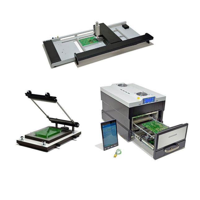
De SMD Starter I prototype-productielijn bestaat uit de TSD240 stencilprinter, de PlaceMAN SMD-plaatsingsmachine en de 3LHR10 reflow-oven. Stencilprinter SD240 (+ metalen rakel 155 mm) Stencilformaat: max. 175 x 255 mm Boardformaat: max. 180 x 240 mm Afmetingen basiseenheid: 410 x 270 x 110 mm Gewicht: 6,7 kg incl. metalen rakel 155 mm incl. 8 magneten om de printplaat vast te houden, waarvan 6 met M3-instelschroef incl. transparante plaatsingshulp en viltstift Handmatige SMD-plaatsingsmachine PlaceMAN voor standaardcomponenten incl. vacuümpomp (zonder feeders, camera, monitor en dispenser) Uitgerust met soepel lopende plaatsingsarm, plaatsingskop met eenhandsbediening, rotatie van de Z-as en automatische vacuümafsluiting, incl. printplaathouder, vacuümunit en 2 plaatsingsmondstukken met rubberen zuignappen. Capaciteit feeders (niet inbegrepen) 2x invoercassette voor 10 x 8 mm rollen links 4x invoercassette voor toevoereenheden van elk 5 magazijnen Verdere toevoersystemen zijn mogelijk binnen het plaatsingsgebied, bijvoorbeeld een insteeksysteem voor strooktoevoer. Afmetingen Basiseenheid (LxBxH): 765 x 390 x 210 mm Met invoercassette voor 10 x 8 mm rollen (LxBxH): 765 x 390 x 210 mm Met voedingscassette voor 10 x 8 mm rollen en voedingscassette voor magazijninvoer (LxBxH): 765 x 430 x 210 mm (hoogte kan variëren afhankelijk van de lengte van het magazijn) Met voedingscassette voor 10 x 8 mm rollen incl. houder voor 10 rollen en voedingscassette voor magazijninvoer (LxBxH): 765 x 430 x 210 mm (hoogte kan variëren afhankelijk van de lengte van het magazijn) Specificaties Gewicht basiseenheid: ca. 6 kg As verplaatsing (x,y,z): 470 x 230 x 15 mm Max. Werkgebied: 380 x 240 mm Max. PCB-formaat: 230 x 360 mm Voeding Netadapter: 230/12 V, 800 mA Voeding vacuümpomp: 230 V, 6 W 3LHR10 Reflow Oven (programmeerbaar voor loodvrij solderen met handmatige lade en met tabletbediening) Reflow-oven met IR- en convectieverwarming. Geforceerde hete lucht convectie zorgt voor een gelijkmatig temperatuurprofiel in de hele oven. Na het handmatige openen van de afsluiting worden de ventilatoren ingeschakeld en wordt de gesoldeerde printplaat snel afgekoeld. Kleine reflow-oven met handmatige opening Klaar voor Industrie 4.0, Bluetooth-communicatie + tablet IR + convectieverwarming. Android-app voor verbinding met tablet of smartphone 100 verschillende gebruikersprogramma's Leveringsomvang: 3LHR10, tablet met app, beschermhoes voor tablet, 4 printplaathouders, extern thermokoppel, handleiding in tablet Toepassing Sluit de oven aan op het elektriciteitsnet en sluit de optioneel verkrijgbare afzuigunit (3LFE10S) aan op de luchtafvoeraansluiting. Na de eerste keer inschakelen zoekt de oven naar een tablet of smartphone. Wanneer beide verbonden zijn in de Android-app, selecteer je de programmering van de oven. Hier kunnen de temperatuur en voorverwarmingstijd worden ingesteld, evenals andere dingen. Registreer je met de tablet om de software in zijn geheel te kunnen gebruiken. Als de oven al geprogrammeerd is, kan de gebruiker het proces bedienen met de knoppen en het display aan de voorkant. Er klinkt een toon wanneer het reflow proces is voltooid. Er wordt ook een signaal weergegeven op de tablet/smartphone. De lade moet nu handmatig worden geopend. De Android-app geeft de processtatus, tijd en temperatuur of andere informatie weer. Specificaties Netaansluiting: 230 V, 50 Hz Maximaal vermogen: 3100 W Temperaturen: 50-260°C Afmetingen: 510 x 370 x 340 mm Maximaal gewicht: 16 kg Afmetingen rooster: 350 x 220 mm Maximale afmetingen van de printplaat: 300 x 200 mm Maximale componenthoogte op de PCB: 50 mm boven, 30 mm onder Leveringsomvang Stencilprinter TSD240 SMD-plaatsingsmachine PlaceMAN Reflow-oven 3LHR10
Most people are increasingly confronted with the applications of Artificial Intelligence (AI). Music or video ratings, navigation systems, shopping advice, etc. are based on methods that can be attributed to this field.
The term Artificial Intelligence was coined in 1956 at an international conference known as the Dartmouth Summer Research Project. One basic approach was to model the functioning of the human brain and to construct advanced computer systems based on this. Soon it should be clear how the human mind works. Transferring it to a machine was considered only a small step. This notion proved to be a bit too optimistic. Nevertheless, the progress of modern AI, or rather its subspecialty called Machine Learning (ML), can no longer be denied.
In this book, several different systems will be used to get to know the methods of machine learning in more detail. In addition to the PC, both the Raspberry Pi and the Maixduino will demonstrate their capabilities in the individual projects. In addition to applications such as object and facial recognition, practical systems such as bottle detectors, person counters, or a “talking eye” will also be created.
The latter is capable of acoustically describing objects or faces that are detected automatically. For example, if a vehicle is in the field of view of the connected camera, the information 'I see a car!' is output via electronically generated speech. Such devices are highly interesting examples of how, for example, blind or severely visually impaired people can also benefit from AI systems.
,
van Lobna Belarbi
Kickstart Your Electronics Journey with Elektor’s Learning Collection
Whether you're new to electronics or aiming to level up your embedded skills, Elektor’s Learning Collection delivers expert-curated kits, courses, and hands-on bundles. The first...