Trade products
-
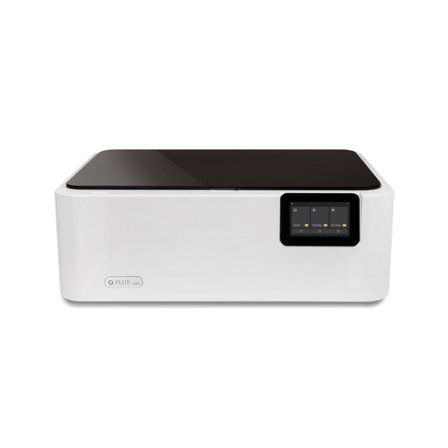
FLUX FLUX Ador Laser Cutter (20 W)
FLUX Ador is the world's first color printing laser cutter. Powered by three high-quality, interchangeable modules, Ador enables you to engrave and cut though a wide range of materials while enhancing your projects with a pop of color. New creative potential with Ador Whether you’re an educator, small business, crafter or designer, with Ador, the application boundary is for you to define. Easy to use Place material then autofocus Drag and drop your design Engrave, cut or print Project Completed! Big workspace, big ideas Ador offers a big working space of 430 x 300 mm, with a depth of 30 mm, expanding the horizons of your creativity. Specifications Dimensions 637 x 488 x 226 mm Weight 19 kg Work Area X&Y: 20 W Diode laser: 430 x 300 mm (X & Y varies with different modules)Z: 30 mm (for all modules) & 20 mm (with prism) Camera Preview Area Whole work area Voltage AC 110-240 V Touch Panel Yes, 8 inches (diagonal) Camera 8 MP I/O USB / WiFi Laser Spec W Diode laser Module Laser Moving Speed 0~400 mm/s Laser Cutting Thickness Varies for different materials Software Mode Vector / Graphic (monochrome, gray scale) Operating System Windows / macOS / Linux Software File Type JPG / PNG / SVG / DXF Included FLUX Ador 20 W diode laser module 6x prism lift Power adapter Power cord Hex key Vent Hose Vent hose Duct Clamp Wooden test piece Laser Cutter Lubricant Downloads Firmware
€ 1.935,00
Leden identiek
-

Rigol Rigol DSA815-TG Spectrumanalyzer (9 kHz – 1.5 GHz)
Highlights Frequency: 1.5 GHz DANL: -155 dBm Phase Noise: -80 dBc/Hz RBW: 10 Hz Tracking Generator Specificaties All-Digital IF Technology Frequency Range from 9 kHz up to 1.5 GHz Min. -161 dBm Displayed Average Noise Level (Typ.) Min. < -98 dBc/Hz @ 10 kHz Offset Phase Noise Level Measurement Uncertainty < 0.8 dB 10 Hz Minimum Resolution Bandwidth Up to 1.5 GHz Tracking Generator Advanced Measurement Functions (Opt.) EMI Filter & Quasi-Peak Detector Kit (Opt.) VSWR Measurement Kit (Opt.) PC Software (Opt.) Optional RF TX/RX Training Kit Optional RF Accessories (Cable, Adaptor, Attenuator, Bridge ...) Complete Connectivity: LAN (LXI), USB Host & Device, GPIB (Opt.) 8 Inch WVGA (800x480) Display Compact Size, Light Weight Design Inbegrepen 1x Rigol DSA815-TG Spectrumanalyzer 1x Power cord 1x USB cable
€ 974,66
-

Rigol Rigol RSA3015E-TG Real-time Spectrumanalyzer (9 kHz – 1.5 GHz)
Highlights Frequency: 1.5 GHz DANL: -161 dBm Phase Noise: -102 dBc/Hz RBW: 1 Hz Specificaties Ultra-Real technology Frequency: up to 1.5 GHz Displayed average noise level (DANL): <-161 dBm (typical) Phase noise: <-102 dBc/Hz (typical) Level measurement uncertainty: <1.0 dB 1.5 GHz tracking generator Min. RBW 1 Hz Up to 10 MHz real-time analysis bandwidth Multiple measurement modes Various advanced measurement functions EMI measurement application (option) Multiple trigger modes and trigger masks Density, spectrogram, and other display modes PC software options 10.1'' capacitive multi-touch screen; supporting touch gestures USB, LAN, HDMI and other communication and display interfaces Inbegrepen 1x Rigol RSA3015E-TG Spectrum Analyzer 1x Power cord 1x USB cable
€ 2.176,79
-

Rigol Rigol DG2102 Function/Arbitrary Waveform Generator (100 MHz)
Highlights Output Frequency (Sine): 100 MHz Output Frequency (Square): 25 MHz Channels: 2 Arbitrary Waveform Length: 16 Mpts Kenmerken Unique SiFi II (Signal Fidelity II) technology: generate the arbitrary waveforms point by point; recover the signal without distortion; sample rate accurate and adjustable; jitter of all the output waveforms (including Sine, Pulse, etc.) as low as 200 ps 16 Mpts memory depth per channel for arbitrary waveforms Standard dual-channel with the same performance, equivalent to two independent signal sources High frequency stability: ±1 ppm; low phase noise: -105 dBc/Hz Built-in high-order harmonic generator (at most 8-order harmonics) Built-in 7 digits/s, 240 MHz bandwidth full featured frequency counter Up to 160 built-in arbitrary waveforms, covering the common signals in engineering application, medical electronics, auto electronics, math processing, and other various fields Sample rate up to 250 MSa/s, vertical resolution 16 bits Arbitrary waveform sequence editing function available; arbitrary waveforms also can be generated through the PC software Various analog and digital modulation functions: AM, FM, PM, ASK, FSK, PSK, and PWM. Standard waveform combine function, capable of outputting specified waveforms combined with the basic waveforms Standard channel tracking function, when enabled, all the parameters of both channels are updated based on users' configurations Standard interface: USB Host&Device and LAN (LXI Core 2011 Device); USB-GPIB function supported 4.3'' TFT Inbegrepen 1x Rigol DG2102 Function/Arbitrary Waveform Generator 1x Power cord 1x USB cable
€ 1.087,79
-

Rigol Rigol DG2072 Function/Arbitrary Waveform Generator (70 MHz)
Highlights Output Frequency (Sine): 70 MHz Output Frequency (Square): 20 MHz Channels: 2 Arbitrary Waveform Length: 16 Mpts Kenmerken Unique SiFi II (Signal Fidelity II) technology: generate the arbitrary waveforms point by point; recover the signal without distortion; sample rate accurate and adjustable; jitter of all the output waveforms (including Sine, Pulse, etc.) as low as 200 ps 16 Mpts memory depth per channel for arbitrary waveforms Standard dual-channel with the same performance, equivalent to two independent signal sources High frequency stability: ±1 ppm; low phase noise: -105 dBc/Hz Built-in high-order harmonic generator (at most 8-order harmonics) Built-in 7 digits/s, 240 MHz bandwidth full featured frequency counter Up to 160 built-in arbitrary waveforms, covering the common signals in engineering application, medical electronics, auto electronics, math processing, and other various fields Sample rate up to 250 MSa/s, vertical resolution 16 bits Arbitrary waveform sequence editing function available; arbitrary waveforms also can be generated through the PC software Various analog and digital modulation functions: AM, FM, PM, ASK, FSK, PSK, and PWM. Standard waveform combine function, capable of outputting specified waveforms combined with the basic waveforms Standard channel tracking function, when enabled, all the parameters of both channels are updated based on users' configurations Standard interface: USB Host&Device and LAN (LXI Core 2011 Device); USB-GPIB function supported 4.3'' TFT Inbegrepen 1x Rigol DG2072 Function/Arbitrary Waveform Generator 1x Power cord 1x USB cable
€ 882,09
-

Rigol Rigol DG2052 Function/Arbitrary Waveform Generator (50 MHz)
Highlights Output Frequency (Sine): 50 MHz Output Frequency (Square): 15 MHz Channels: 2 Arbitrary Waveform Length: 16 Mpts Kenmerken Unique SiFi II (Signal Fidelity II) technology: generate the arbitrary waveforms point by point; recover the signal without distortion; sample rate accurate and adjustable; jitter of all the output waveforms (including Sine, Pulse, etc.) as low as 200 ps 16 Mpts memory depth per channel for arbitrary waveforms Standard dual-channel with the same performance, equivalent to two independent signal sources High frequency stability: ±1 ppm; low phase noise: -105 dBc/Hz Built-in high-order harmonic generator (at most 8-order harmonics) Built-in 7 digits/s, 240 MHz bandwidth full featured frequency counter Up to 160 built-in arbitrary waveforms, covering the common signals in engineering application, medical electronics, auto electronics, math processing, and other various fields Sample rate up to 250 MSa/s, vertical resolution 16 bits Arbitrary waveform sequence editing function available; arbitrary waveforms also can be generated through the PC software Various analog and digital modulation functions: AM, FM, PM, ASK, FSK, PSK, and PWM. Standard waveform combine function, capable of outputting specified waveforms combined with the basic waveforms Standard channel tracking function, when enabled, all the parameters of both channels are updated based on users' configurations Standard interface: USB Host&Device and LAN (LXI Core 2011 Device); USB-GPIB function supported 4.3'' TFT Inbegrepen 1x Rigol DG2052 Function/Arbitrary Waveform Generator 1x Power cord 1x USB cable
€ 652,19
-

Rigol Rigol DS1202Z-E 2-kanaals Oscilloscoop (200 MHz)
Specificaties Bandwidth: 200 MHz Analog Channels: 2 Real-time sample rate up to 1 GS/s Memory depth up to 24 Mpts Up to 30,000 wfms/s waveform capture rate Up to 60,000 frames hardware real-time waveform recording and playback functions Innovative 'UltraVision' technology Various trigger and bus decoding functions Low noise floor, vertical scale range: 1 mV/div to 10 V/div Various interfaces: USB Host&Device, LAN (LXI), AUX Compact size, light weight, easy to use 7 inch WVGA (800x480) TFT LCD, intensity graded color display Inbegrepen 1x Rigol DS1202Z-E Oscilloscope 1x Power cord 1x USB cable 2x PVP2350 passive oscilloscope probe (350 MHz)
€ 262,27
-

Rigol Rigol DP832 3-kanaals DC-Voeding (0-30 V, 0-3 A, 195 W)
Specificaties Channels: 3 Total Power: 195 Watts Max. Voltage: 30 Volts Max. Current: 3 Amps Low ripple and noise: <350 ?Vrms/2 mVpp Excellent linear regulation rate and load regulation rate Fast transient response time: <50 ?s Some channels are isolated Standard OVP/OCP/OTP protection functions Standard timing output Built-in V,A,W measurements and waveform display Independent control for each channel 3.5 inch TFT display Inbegrepen 1x Rigol DP832 DC Power Supply 1x Power cord 1x USB cable
€ 427,21
-

Rigol Rigol DS1054Z 4-kanaals Oscilloscoop (50 MHz)
Specificaties Bandwidth: 50 MHz Analog Channels: 4 Real-time sample rate up to 1 GS/s Memory depth up to 24 Mpts Up to 30,000 wfms/s waveform capture rate Up to 60,000 frames hardware real-time waveform recording and playback functions Innovative 'UltraVision' technology Various trigger and bus decoding functions Low noise floor, vertical scale range: 1 mV/div to 10 V/div Various interfaces: USB Host&Device, LAN (LXI), AUX Compact size, light weight, easy to use 7 inch WVGA (800x480) TFT LCD, intensity graded color display Inbegrepen 1x Rigol DS1054Z Oscilloscope 1x Power cord 1x USB cable 4x PVP2150 passive oscilloscope probe (150 MHz)
€ 409,00
-
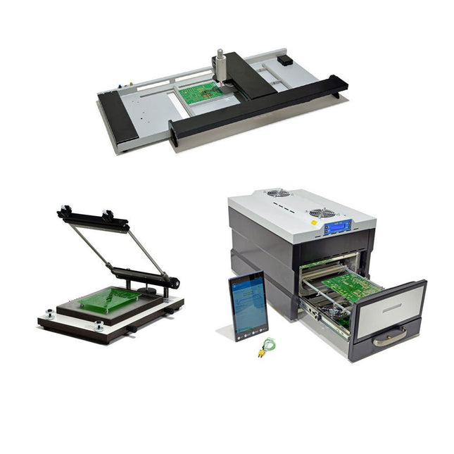
Paggen Werkzeugtechnik SMD Starter I – Productielijn voor prototypes
De SMD Starter I prototype-productielijn bestaat uit de TSD240 stencilprinter, de PlaceMAN SMD-plaatsingsmachine en de 3LHR10 reflow-oven. Stencilprinter SD240 (+ metalen rakel 155 mm) Stencilformaat: max. 175 x 255 mm Boardformaat: max. 180 x 240 mm Afmetingen basiseenheid: 410 x 270 x 110 mm Gewicht: 6,7 kg incl. metalen rakel 155 mm incl. 8 magneten om de printplaat vast te houden, waarvan 6 met M3-instelschroef incl. transparante plaatsingshulp en viltstift Handmatige SMD-plaatsingsmachine PlaceMAN voor standaardcomponenten incl. vacuümpomp (zonder feeders, camera, monitor en dispenser) Uitgerust met soepel lopende plaatsingsarm, plaatsingskop met eenhandsbediening, rotatie van de Z-as en automatische vacuümafsluiting, incl. printplaathouder, vacuümunit en 2 plaatsingsmondstukken met rubberen zuignappen. Capaciteit feeders (niet inbegrepen) 2x invoercassette voor 10 x 8 mm rollen links 4x invoercassette voor toevoereenheden van elk 5 magazijnen Verdere toevoersystemen zijn mogelijk binnen het plaatsingsgebied, bijvoorbeeld een insteeksysteem voor strooktoevoer. Afmetingen Basiseenheid (LxBxH): 765 x 390 x 210 mm Met invoercassette voor 10 x 8 mm rollen (LxBxH): 765 x 390 x 210 mm Met voedingscassette voor 10 x 8 mm rollen en voedingscassette voor magazijninvoer (LxBxH): 765 x 430 x 210 mm (hoogte kan variëren afhankelijk van de lengte van het magazijn) Met voedingscassette voor 10 x 8 mm rollen incl. houder voor 10 rollen en voedingscassette voor magazijninvoer (LxBxH): 765 x 430 x 210 mm (hoogte kan variëren afhankelijk van de lengte van het magazijn) Specificaties Gewicht basiseenheid: ca. 6 kg As verplaatsing (x,y,z): 470 x 230 x 15 mm Max. Werkgebied: 380 x 240 mm Max. PCB-formaat: 230 x 360 mm Voeding Netadapter: 230/12 V, 800 mA Voeding vacuümpomp: 230 V, 6 W 3LHR10 Reflow Oven (programmeerbaar voor loodvrij solderen met handmatige lade en met tabletbediening) Reflow-oven met IR- en convectieverwarming. Geforceerde hete lucht convectie zorgt voor een gelijkmatig temperatuurprofiel in de hele oven. Na het handmatige openen van de afsluiting worden de ventilatoren ingeschakeld en wordt de gesoldeerde printplaat snel afgekoeld. Kleine reflow-oven met handmatige opening Klaar voor Industrie 4.0, Bluetooth-communicatie + tablet IR + convectieverwarming. Android-app voor verbinding met tablet of smartphone 100 verschillende gebruikersprogramma's Leveringsomvang: 3LHR10, tablet met app, beschermhoes voor tablet, 4 printplaathouders, extern thermokoppel, handleiding in tablet Toepassing Sluit de oven aan op het elektriciteitsnet en sluit de optioneel verkrijgbare afzuigunit (3LFE10S) aan op de luchtafvoeraansluiting. Na de eerste keer inschakelen zoekt de oven naar een tablet of smartphone. Wanneer beide verbonden zijn in de Android-app, selecteer je de programmering van de oven. Hier kunnen de temperatuur en voorverwarmingstijd worden ingesteld, evenals andere dingen. Registreer je met de tablet om de software in zijn geheel te kunnen gebruiken. Als de oven al geprogrammeerd is, kan de gebruiker het proces bedienen met de knoppen en het display aan de voorkant. Er klinkt een toon wanneer het reflow proces is voltooid. Er wordt ook een signaal weergegeven op de tablet/smartphone. De lade moet nu handmatig worden geopend. De Android-app geeft de processtatus, tijd en temperatuur of andere informatie weer. Specificaties Netaansluiting: 230 V, 50 Hz Maximaal vermogen: 3100 W Temperaturen: 50-260°C Afmetingen: 510 x 370 x 340 mm Maximaal gewicht: 16 kg Afmetingen rooster: 350 x 220 mm Maximale afmetingen van de printplaat: 300 x 200 mm Maximale componenthoogte op de PCB: 50 mm boven, 30 mm onder Leveringsomvang Stencilprinter TSD240 SMD-plaatsingsmachine PlaceMAN Reflow-oven 3LHR10
€ 6.549,00
Leden identiek
-
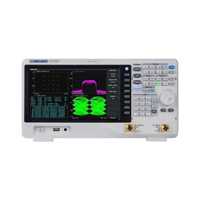
Siglent Siglent SSA3075X Plus Spectrum Analyzer (9 kHz - 7,5 GHz)
De Siglent SSA3015X Plus spectrum analyzer is een krachtig en flexibel hulpmiddel voor RF signaal- en netwerkanalyse. Met een frequentiebereik van 7,5 GHz levert de analyzer betrouwbare automatische metingen en meerdere werkingsmodi: spectrum analyzer als basisfunctie, en optionele functies als RF-vermogensmeting, vectorsignaal-modulatieanalyse, reflectiemeting en EMI-test.Toepassingen zijn onder meer monitoring/evaluatie van zendsignalen, metingen op locatie, S-parameter meting, analoge/digitale modulatie analyse, EMI pre-compliance test, onderzoek en ontwikkeling, onderwijs, productie en onderhoud.Kenmerken Spectrum analyzer frequentiebereik van 9 kHz tot 7,5 GHz –165 dBm/Hz Displayed Average Noise Level (typ.) –98 dBc/Hz. @ 10 kHz Offset Phase Noise (1 GHz, typ.) Level Measurement Uncertainty< 0,7 dB (typ.) 1 Hz minimale Resolution Bandwidth (RBW) Voorversterker (standaard) Tracking generator (inbegrepen, gratis) Analoge en digitale signaalmodulatie-analyse modus (optioneel) Reflectie meetkit (optioneel) EMI filter en quasi-peak detector kit (optioneel) Advanced Measurement Kit (optioneel) 10,1-inch multi-touch scherm, muis en toetsenbord ondersteund Webbrowser afstandsbediening op pc en mobiele terminals, en bediening via files Specificaties SSA3015X Plus SSA3021X Plus SSA3032X Plus SSA3075X Plus Frequentiebereik 9 kHz ~ 1,5 GHz 9 kHz ~ 2,1 GHz 9 kHz ~ 3,2 GHz 9 kHz ~ 7,5 GHz Resolutie bandbreedte 1 Hz ~ 1 MHz 1 Hz ~ 1 MHz 1 Hz ~ 1 MHz 1 Hz ~ 3 MHz Phase Noise <–99 dBc/Hz <–98 dBc/Hz <–98 dBc/Hz <–98 dBc/Hz Total Amplitude Accuracy < 1,2 dB < 0,7 dB < 0,7 dB < 0,7 dB Display Average Noise Level –156 dBm/Hz –161 dBm/Hz –161 dBm/Hz –165 dBm/Hz Inbegrepen Siglent SSA3075X Plus spectrum analyzer USB kabel Netsnoer Quick Start gids Downloads Datasheet Manual Documentation Firmware
€ 7.875,89
-

Siglent Siglent SSA3021X Plus Spectrum Analyzer (9 kHz - 2,1 GHz)
De Siglent SSA3021X Plus spectrum analyzer is een krachtig en flexibel hulpmiddel voor RF signaal- en netwerkanalyse. Met een frequentiebereik van 2,1 GHz levert de analyzer betrouwbare automatische metingen en meerdere werkingsmodi: spectrum analyzer als basisfunctie, en optionele functies als RF-vermogensmeting, vectorsignaal-modulatieanalyse, reflectiemeting en EMI-test. Toepassingen zijn onder meer monitoring/evaluatie van zendsignalen, metingen op locatie, S-parameter meting, analoge/digitale modulatie analyse, EMI pre-compliance test, onderzoek en ontwikkeling, onderwijs, productie en onderhoud. Kenmerken Spectrum analyzer frequentiebereik van 9 kHz tot 2,1 GHz –161 dBm/Hz Displayed Average Noise Level (typ.) –98 dBc/Hz. @ 10 kHz Offset Phase Noise (1 GHz, typ.) Level Measurement Uncertainty< 0,7 dB (typ.) 1 Hz minimale Resolution Bandwidth (RBW) Voorversterker (standaard) Tracking generator (inbegrepen, gratis) Analoge en digitale signaalmodulatie-analyse modus (optioneel) Reflectie meetkit (optioneel) EMI filter en quasi-peak detector kit (optioneel) Advanced Measurement Kit (optioneel) 10,1-inch multi-touch scherm, muis en toetsenbord ondersteund Webbrowser afstandsbediening op pc en mobiele terminals, en bediening via files Specificaties SSA3015X Plus SSA3021X Plus SSA3032X Plus SSA3075X Plus Frequentiebereik 9 kHz ~ 1,5 GHz 9 kHz ~ 2,1 GHz 9 kHz ~ 3,2 GHz 9 kHz ~ 7,5 GHz Resolutie bandbreedte 1 Hz ~ 1 MHz 1 Hz ~ 1 MHz 1 Hz ~ 1 MHz 1 Hz ~ 3 MHz Phase Noise <–99 dBc/Hz <–98 dBc/Hz <–98 dBc/Hz <–98 dBc/Hz Total Amplitude Accuracy < 1,2 dB < 0,7 dB < 0,7 dB < 0,7 dB Display Average Noise Level –156 dBm/Hz –161 dBm/Hz –161 dBm/Hz –165 dBm/Hz Inbegrepen Siglent SSA3021X Plus spectrum analyzer USB kabel Netsnoer Quick Start gids Downloads Datasheet Manual Documentation Firmware
€ 1.777,49
-

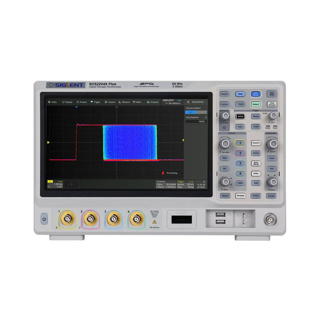
Siglent Siglent SDS2354X Plus 4-ch Oscilloscope (350 MHz)
Siglent's SDS2000X Plus series Digital Storage Oscilloscopes are available in bandwidths of 100 MHz, 200 MHz, and 350 MHz, have a maximum sample rate of 2 GSa/s, a maximum record length of 200 Mpts/ch, and up to 4 analog channels + 16 digital channels mixed-signal analysis ability. The SDS2000X Plus series employs Siglent’s SPO technology with a maximum waveform capture rate of up to 120,000 wfm/s (normal mode, up to 500,000 wfm/s in Sequence mode), 256-level intensity grading display function plus a color temperature display mode. It also employs an innovative digital trigger system with high sensitivity and low jitter. The trigger system supports multiple powerful triggering modes including serial bus triggering. History waveform recording, Sequence acquisition, Search and Navigate functions allow for extended waveform records to be captured, stored, and analyzed. An impressive array of measurement and math capabilities, options for a 50 MHz waveform generator, as well as serial decoding, mask test, bode plot, and power analysis are also features of the SDS2000X Plus. A 10-bit acquisition mode helps to satisfy applications that require more than 8-bit resolution. The large 10.1’’ capacitive touch screen supports multi-touch gestures, while the remote web control, mouse and external keyboard support greatly improve the operating efficiency of the SDS2000X Plus. Features 100 MHz, 200 MHz, 350 MHz (upgradable to 500 MHz) models Real-time sampling rate up to 2 GSa/s Record length up to 200 Mpts Serial bus triggering and decoder, supports I²C, SPI, UART, CAN, LIN, CAN FD, FlexRay, I²S and MIL-STD-1553B Provide 10 bit mode, Vertical and Horizontal Zoom Capacitive touch screen supports multi-touch gestures Siglent SDS2000X Plus Oscilloscopes SDS2102X Plus SDS2104X Plus SDS2204X Plus SDS2354X Plus Bandwidth 100 MHz 100 MHz 200 MHz 350 MHz Channels 2 4 4 4 Real-time sampling rate 2 GSa/s 2 GSa/s 2 GSa/s 2 GSa/s Capture rate 120,000 wfm/s 120,000 wfm/s 120,000 wfm/s 120,000 wfm/s Memory depth 200 Mpts/ch 200 Mpts/ch 200 Mpts/ch 200 Mpts/ch Included Siglent SDS2354X Plus Oscilloscope Passive probes Power cord USB cable Manual Downloads Datasheet Manual Quick guide User manual Firmware
€ 2.515,83
-
Siglent Siglent SDS2204X Plus 4-ch Oscilloscope (200 Mhz)
Siglent's SDS2000X Plus series Digital Storage Oscilloscopes are available in bandwidths of 100 MHz, 200 MHz, and 350 MHz, have a maximum sample rate of 2 GSa/s, a maximum record length of 200 Mpts/ch, and up to 4 analog channels + 16 digital channels mixed-signal analysis ability. The SDS2000X Plus series employs Siglent’s SPO technology with a maximum waveform capture rate of up to 120,000 wfm/s (normal mode, up to 500,000 wfm/s in Sequence mode), 256-level intensity grading display function plus a color temperature display mode. It also employs an innovative digital trigger system with high sensitivity and low jitter. The trigger system supports multiple powerful triggering modes including serial bus triggering. History waveform recording, Sequence acquisition, Search and Navigate functions allow for extended waveform records to be captured, stored, and analyzed. An impressive array of measurement and math capabilities, options for a 50 MHz waveform generator, as well as serial decoding, mask test, bode plot, and power analysis are also features of the SDS2000X Plus. A 10-bit acquisition mode helps to satisfy applications that require more than 8-bit resolution. The large 10.1’’ capacitive touch screen supports multi-touch gestures, while the remote web control, mouse and external keyboard support greatly improve the operating efficiency of the SDS2000X Plus. Features 100 MHz, 200 MHz, 350 MHz (upgradable to 500 MHz) models Real-time sampling rate up to 2 GSa/s Record length up to 200 Mpts Serial bus triggering and decoder, supports I²C, SPI, UART, CAN, LIN, CAN FD, FlexRay, I²S and MIL-STD-1553B Provide 10 bit mode, Vertical and Horizontal Zoom Capacitive touch screen supports multi-touch gestures Siglent SDS2000X Plus Oscilloscopes SDS2102X Plus SDS2104X Plus SDS2204X Plus SDS2354X Plus Bandwidth 100 MHz 100 MHz 200 MHz 350 MHz Channels 2 4 4 4 Real-time sampling rate 2 GSa/s 2 GSa/s 2 GSa/s 2 GSa/s Capture rate 120,000 wfm/s 120,000 wfm/s 120,000 wfm/s 120,000 wfm/s Memory depth 200 Mpts/ch 200 Mpts/ch 200 Mpts/ch 200 Mpts/ch Included Siglent SDS2204X Plus Oscilloscope Passive probes Power cord USB cable Manual Downloads Datasheet Manual Quick guide User manual Firmware
€ 1.838,23
-
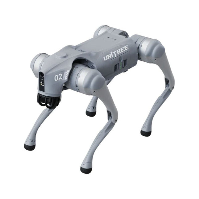
Unitree Unitree Go2 Edu Viervoetige Robot
Tijdelijke vertraging in de levering van Unitree-robots Op dit moment ervaren wij, net als andere leveranciers, vertragingen in de levering van Unitree-robots. Een zending van onze leverancier staat vast bij de douane, waardoor we eerder geplaatste bestellingen later kunnen uitleveren dan gepland. We werken hier actief aan samen met onze leverancier en verwachten op korte termijn meer duidelijkheid, maar kunnen helaas geen garanties geven. Ook een nieuwe zending is onderweg, maar deze zal nog enige tijd op zich laten wachten. Omdat andere leveranciers met dezelfde uitdagingen te maken hebben, is overstappen naar een andere partij momenteel geen snellere oplossing. Onze prioriteit ligt bij het uitleveren van bestaande bestellingen. Mocht je vragen hebben of je bestelling willen aanpassen, neem dan gerust contact op met onze customer service. We houden je op de hoogte van verdere ontwikkelingen. Bedankt voor je geduld en vertrouwen! De Unitree Go2-serie bestaat uit viervoetige robots voor onderzoek en ontwikkeling van autonome systemen op het gebied van mens-robotinteractie (HRI), SLAM en transport. Dankzij de vier poten en de 12DOF kan deze robot op verschillende terreinen uit de voeten. De Go2 is uitgerust met een geperfectioneerd aandrijf- en energiebeheersysteem, dat een snelheid (afhankelijk van de uitvoering) tot 3,7 m/s of 11,88 km/u mogelijk maakt met een gebruiksduur tot 4 uur. Bovendien hebben de motoren een koppel van 45 Nm op het lichaam/dijen en de knieën, wat ook sprongen of backflips mogelijk maakt. Kenmerken Superherkenningssysteem: 4D LIDAR L1 Maximale loopsnelheid: ca. 5 m/s Maximale gewrichtskracht: ca. 45 Nm Draadloze module: WiFi 6/Bluetooth/4G Ultralange batterijduur: ca. 2-4 uur (lange batterijduur gemeten in de praktijk) Intelligent zijvolgsysteem: ISS 2.0 Specificaties Trackingmodule: Op afstand bestuurbaar of automatisch volgen Frontcamera: Beeldoverdrachtsresolutie 1280x720, gezichtsveld 120°, ultragroothoeklens voor rijke helderheid Frontlamp: Verlicht de weg voor u helder 4D LiDAR L1: 360° x 90° omnidirectionele ultragroothoekscanning maakt automatisch vermijden mogelijk met een kleine dode hoek en stabiele werking 12 kniegewrichtmotoren: Sterk en krachtig, mooi en eenvoudig, gloednieuwe visuele ervaring Intercommicrofoon: Effectieve communicatie zonder scenariobeperkingen Zelfoprollende riem: Gemakkelijk te dragen en te laden Stabieler, krachtiger met geavanceerde apparaten: 3D LiDAR, 4G ESIM-kaart, wifi 6 met dualband, Bluetooth 5.2 voor stabiele verbinding en bediening op afstand. Krachtige rekenkern: Bewegingscontroller, krachtige ARM-processor, verbeterde AI-algoritmeprocessor, externe ORIN NX/NANO. Slimme batterij: Standaard 8000 mAh-batterij, duurzame 15000 mAh-batterij, bescherming tegen oververhitting, overladen en kortsluiting. Luidspreker voor het afspelen van muziek: Luister naar muziek wanneer u dat wilt. Unitree Go2 varianten De Go2 overtuigt niet alleen met zijn technische mogelijkheden, maar ook met een modern en slank design dat hem een futuristische uitstraling geeft en een echte blikvanger maakt. De Go2 Air is speciaal ontworpen voor demo's en presentaties. Met zijn basisfuncties biedt hij een solide basis voor het demonstreren van de bewegingsmogelijkheden en functionaliteit van een viervoetige robot. Belangrijk: De Go2 Air wordt geleverd zonder controller. Deze is optioneel verkrijgbaar. Met een krachtige 8-core high-performance CPU bieden de Pro en Edu de indrukwekkende rekenkracht die nodig is voor complexe taken en veeleisende berekeningen. Dit maakt snellere en efficiëntere gegevensverwerking mogelijk en maakt de Pro en Edu een betrouwbare partner voor uw projecten. Vanaf de Edu-versie is de Go2 programmeerbaar en biedt hij eindeloze mogelijkheden voor het ontwikkelen en onderzoeken van uw eigen roboticatoepassingen. De Go2 kan ook een staphoogte tot 14 cm aan. Dit maakt het een ideaal hulpmiddel voor onderzoek, onderwijs en de instap in de wereld van robotica. De Go2 Edu wordt geleverd met een afstandsbediening die eenvoudige en intuïtieve bediening biedt. Je krijgt er ook een dockingstation bij met een indrukwekkende rekenkracht van 100 TOPS, dat is uitgerust met krachtige AI-algoritmen en technische ondersteuning biedt. De Go2 Edu is uitgerust met een krachtige accu van 15.000 mAh, goed voor een indrukwekkende gebruiksduur tot wel 4 uur. Deze lange gebruiksduur stelt de robot in staat om langere verkenningsmissies uit te voeren en veeleisende taken te voltooien. Modelvergelijking Air Pro Edu/Edu Plus Afmetingen (staand) 70 x 31 x 40 cm 70 x 31 x 40 cm 70 x 31 x 40 cm Afmetingen (hurkend) 76 x 31 x 20 cm 76 x 31 x 20 cm Materiaal Aluminiumlegering + zeer sterke technische kunststof Aluminiumlegering + zeer sterke technische kunststof Aluminiumlegering + zeer sterke technische kunststof kunststof Gewicht (met accu) ongeveer 15 kg ongeveer 15 kg ongeveer 15 kg Spanning 28~33,6 V 28~33,6 V Piekvermogen ongeveer 3000 W ongeveer 3000 W ongeveer 3000 W Laadvermogen ≈7 kg (MAX ~ 10 kg) ≈8 kg (MAX ~ 10 kg) ≈8 kg (MAX ~ 12 kg) Snelheid 0~2,5 m/s 0~3,5 m/s 0~3,7 m/s (MAX ~ 5 m/s) Maximale klim- en valhoogte ongeveer 15 cm ongeveer 16 cm ongeveer 16 cm Maximale klimhoek 30° 40° 40° Basisrekenkracht N.v.t. 8-core High-performance CPU 8-core high-performance CPU Aluminium kniegewrichtsmotor 12 stuks 12 stuks 12 stuks Intra-gewrichtscircuit (knie) ✓ ✓ ✓ Heatpipe-koeler ✓ ✓ ✓ Bewegingsbereik Behuizing: -48~48° Lichaam: -48~48° Lichaam: -48~48° Dij: -200°~90° Dij: -200°~90° Dij: -200°~90° Schacht: -156°~-48° Schacht: -156°~-48° Schacht: -156°~-48° Maximaal koppel N.v.t. ongeveer 45 N.m ongeveer 45 N.m Supergroothoek 3D LiDAR ✓ ✓ Draadloze vectorpositionering Module N.v.t. ✓ ✓ HD-groothoekcamera ✓ ✓ Voeteinde-krachtsensor N.v.t. N.v.t. ✓ Basisactie ✓ ✓ ✓ Automatisch schalen band N.v.t. ✓ N.v.t. Verbeterde Intelligent OTA ✓ ✓ ✓ RTT 2.0 Beeldoverdracht ✓ ✓ ✓ App Basis Afstandsbediening ✓ ✓ ✓ App Gegevensweergave ✓ ✓ ✓ App Grafisch Programma ✓ ✓ ✓ Koplamp (3 W) ✓ ✓ ✓ Wifi 6 met dualband ✓ ✓ ✓ Bluetooth 5.2/4.2/2.1 ✓ ✓ ✓ 4G-module N.v.t. CN/GB CN/GB Spraakfunctie N.v.t. ✓ ✓ Muziek afspelen N.v.t. ✓ ✓ ISS 2.0 Intelligent zijvolgsysteem N.v.t. ✓ ✓ Intelligente detectie en vermijding ✓ ✓ ✓ Secundaire ontwikkeling N/A N/A ✓ Handmatige controller Optioneel Optioneel ✓ Module met hoge rekenkracht N.v.t. N.v.t. Edu: TOP 40 rekenkracht Edu Plus: TOP 100 rekenkracht NVIDIA Jetson Orin (optioneel) Slimme batterij Standaard (8000 mAh) Standaard (8000 mAh) Lange batterijduur (15000 mAh) Batterijduur 1-2 uur 1-2 uur 2-4 uur Oplader Standaard (33,6 V, 3,5 A) Standaard (33,6 V, 3,5 A) Snelladen (33,6 V, 9 A) Inbegrepen 1x Unitree Go2 Edu 1x Unitree Go2 afstandsbediening 1x Unitree Go2 batterij (15000 mAh) 1x Unitree Dockingstation met 40 TOPS rekenkracht Downloads Documentation iOS/Android apps GitHub
€ 12.499,00
Leden identiek
-

Unitree Unitree Go2 Air Viervoetige Robot
Tijdelijke vertraging in de levering van Unitree-robots Op dit moment ervaren wij, net als andere leveranciers, vertragingen in de levering van Unitree-robots. Een zending van onze leverancier staat vast bij de douane, waardoor we eerder geplaatste bestellingen later kunnen uitleveren dan gepland. We werken hier actief aan samen met onze leverancier en verwachten op korte termijn meer duidelijkheid, maar kunnen helaas geen garanties geven. Ook een nieuwe zending is onderweg, maar deze zal nog enige tijd op zich laten wachten. Omdat andere leveranciers met dezelfde uitdagingen te maken hebben, is overstappen naar een andere partij momenteel geen snellere oplossing. Onze prioriteit ligt bij het uitleveren van bestaande bestellingen. Mocht je vragen hebben of je bestelling willen aanpassen, neem dan gerust contact op met onze customer service. We houden je op de hoogte van verdere ontwikkelingen. Bedankt voor je geduld en vertrouwen! De Unitree Go2-serie bestaat uit viervoetige robots voor onderzoek en ontwikkeling van autonome systemen op het gebied van mens-robotinteractie (HRI), SLAM en transport. Dankzij de vier poten en de 12DOF kan deze robot op verschillende terreinen uit de voeten. De Go2 is uitgerust met een geperfectioneerd aandrijf- en energiebeheersysteem, dat een snelheid (afhankelijk van de uitvoering) tot 3,7 m/s of 11,88 km/u mogelijk maakt met een gebruiksduur tot 4 uur. Bovendien hebben de motoren een koppel van 45 Nm op het lichaam/dijen en de knieën, wat ook sprongen of backflips mogelijk maakt. Kenmerken Superherkenningssysteem: 4D LIDAR L1 Maximale loopsnelheid: ca. 5 m/s Maximale gewrichtskracht: ca. 45 Nm Draadloze module: WiFi 6/Bluetooth/4G Ultralange batterijduur: ca. 2-4 uur (lange batterijduur gemeten in de praktijk) Intelligent zijvolgsysteem: ISS 2.0 Specificaties Trackingmodule: Op afstand bestuurbaar of automatisch volgen Frontcamera: Beeldoverdrachtsresolutie 1280x720, gezichtsveld 120°, ultragroothoeklens voor rijke helderheid Frontlamp: Verlicht de weg voor u helder 4D LiDAR L1: 360° x 90° omnidirectionele ultragroothoekscanning maakt automatisch vermijden mogelijk met een kleine dode hoek en stabiele werking 12 kniegewrichtmotoren: Sterk en krachtig, mooi en eenvoudig, gloednieuwe visuele ervaring Intercommicrofoon: Effectieve communicatie zonder scenariobeperkingen Zelfoprollende riem: Gemakkelijk te dragen en te laden Stabieler, krachtiger met geavanceerde apparaten: 3D LiDAR, 4G ESIM-kaart, wifi 6 met dualband, Bluetooth 5.2 voor stabiele verbinding en bediening op afstand. Krachtige rekenkern: Bewegingscontroller, krachtige ARM-processor, verbeterde AI-algoritmeprocessor, externe ORIN NX/NANO. Slimme batterij: Standaard 8000 mAh-batterij, duurzame 15000 mAh-batterij, bescherming tegen oververhitting, overladen en kortsluiting. Luidspreker voor het afspelen van muziek: Luister naar muziek wanneer u dat wilt. Unitree Go2 varianten De Go2 overtuigt niet alleen met zijn technische mogelijkheden, maar ook met een modern en slank design dat hem een futuristische uitstraling geeft en een echte blikvanger maakt. De Go2 Air is speciaal ontworpen voor demo's en presentaties. Met zijn basisfuncties biedt hij een solide basis voor het demonstreren van de bewegingsmogelijkheden en functionaliteit van een viervoetige robot. Belangrijk: De Go2 Air wordt geleverd zonder controller. Deze is optioneel verkrijgbaar. Met een krachtige 8-core high-performance CPU bieden de Pro en Edu de indrukwekkende rekenkracht die nodig is voor complexe taken en veeleisende berekeningen. Dit maakt snellere en efficiëntere gegevensverwerking mogelijk en maakt de Pro en Edu een betrouwbare partner voor uw projecten. Vanaf de Edu-versie is de Go2 programmeerbaar en biedt hij eindeloze mogelijkheden voor het ontwikkelen en onderzoeken van uw eigen roboticatoepassingen. De Go2 kan ook een staphoogte tot 14 cm aan. Dit maakt het een ideaal hulpmiddel voor onderzoek, onderwijs en de instap in de wereld van robotica. De Go2 Edu wordt geleverd met een afstandsbediening die eenvoudige en intuïtieve bediening biedt. Je krijgt er ook een dockingstation bij met een indrukwekkende rekenkracht van 100 TOPS, dat is uitgerust met krachtige AI-algoritmen en technische ondersteuning biedt. De Go2 Edu is uitgerust met een krachtige accu van 15.000 mAh, goed voor een indrukwekkende gebruiksduur tot wel 4 uur. Deze lange gebruiksduur stelt de robot in staat om langere verkenningsmissies uit te voeren en veeleisende taken te voltooien. Modelvergelijking Air Pro Edu/Edu Plus Afmetingen (staand) 70 x 31 x 40 cm 70 x 31 x 40 cm 70 x 31 x 40 cm Afmetingen (hurkend) 76 x 31 x 20 cm 76 x 31 x 20 cm Materiaal Aluminiumlegering + zeer sterke technische kunststof Aluminiumlegering + zeer sterke technische kunststof Aluminiumlegering + zeer sterke technische kunststof kunststof Gewicht (met accu) ongeveer 15 kg ongeveer 15 kg ongeveer 15 kg Spanning 28~33,6 V 28~33,6 V Piekvermogen ongeveer 3000 W ongeveer 3000 W ongeveer 3000 W Laadvermogen ≈7 kg (MAX ~ 10 kg) ≈8 kg (MAX ~ 10 kg) ≈8 kg (MAX ~ 12 kg) Snelheid 0~2,5 m/s 0~3,5 m/s 0~3,7 m/s (MAX ~ 5 m/s) Maximale klim- en valhoogte ongeveer 15 cm ongeveer 16 cm ongeveer 16 cm Maximale klimhoek 30° 40° 40° Basisrekenkracht N.v.t. 8-core High-performance CPU 8-core high-performance CPU Aluminium kniegewrichtsmotor 12 stuks 12 stuks 12 stuks Intra-gewrichtscircuit (knie) ✓ ✓ ✓ Heatpipe-koeler ✓ ✓ ✓ Bewegingsbereik Behuizing: -48~48° Lichaam: -48~48° Lichaam: -48~48° Dij: -200°~90° Dij: -200°~90° Dij: -200°~90° Schacht: -156°~-48° Schacht: -156°~-48° Schacht: -156°~-48° Maximaal koppel N.v.t. ongeveer 45 N.m ongeveer 45 N.m Supergroothoek 3D LiDAR ✓ ✓ Draadloze vectorpositionering Module N.v.t. ✓ ✓ HD-groothoekcamera ✓ ✓ Voeteinde-krachtsensor N.v.t. N.v.t. ✓ Basisactie ✓ ✓ ✓ Automatisch schalen band N.v.t. ✓ N.v.t. Verbeterde Intelligent OTA ✓ ✓ ✓ RTT 2.0 Beeldoverdracht ✓ ✓ ✓ App Basis Afstandsbediening ✓ ✓ ✓ App Gegevensweergave ✓ ✓ ✓ App Grafisch Programma ✓ ✓ ✓ Koplamp (3 W) ✓ ✓ ✓ Wifi 6 met dualband ✓ ✓ ✓ Bluetooth 5.2/4.2/2.1 ✓ ✓ ✓ 4G-module N.v.t. CN/GB CN/GB Spraakfunctie N.v.t. ✓ ✓ Muziek afspelen N.v.t. ✓ ✓ ISS 2.0 Intelligent zijvolgsysteem N.v.t. ✓ ✓ Intelligente detectie en vermijding ✓ ✓ ✓ Secundaire ontwikkeling N/A N/A ✓ Handmatige controller Optioneel Optioneel ✓ Module met hoge rekenkracht N.v.t. N.v.t. Edu: TOP 40 rekenkracht Edu Plus: TOP 100 rekenkracht NVIDIA Jetson Orin (optioneel) Slimme batterij Standaard (8000 mAh) Standaard (8000 mAh) Lange batterijduur (15000 mAh) Batterijduur 1-2 uur 1-2 uur 2-4 uur Oplader Standaard (33,6 V, 3,5 A) Standaard (33,6 V, 3,5 A) Snelladen (33,6 V, 9 A) Inbegrepen 1x Unitree Go2 Air 1x Unitree Go2 batterij (8000 mAh) Downloads Documentation iOS/Android apps GitHub
€ 2.650,00
Leden identiek
-
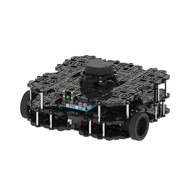
Robotis Robotis TurtleBot3 Waffle Pi (incl. Raspberry Pi 4)
World’s Most Popular ROS PlatformTurtleBot is the most popular open source robot for education and research. The new generation TurtleBot3 is a small, low cost, fully programmable, ROS based mobile robot. It is intended to be used for education, research, hobby and product prototyping.Affordable CostTurtleBot was developed to meet the cost-conscious needs of schools, laboratories and companies. TurtleBot3 is the most affordable robot among the SLAM-able mobile robots equipped with a 360° Laser Distance Sensor LDS-01.ROS StandardThe TurtleBot brand is managed by Open Robotics, which develops and maintains ROS. Nowadays, ROS has become the go-to platform for all the roboticists around the world. TurtleBot can be integrated with existing ROS-based robot components, but TurtleBot3 can be an affordable platform for whom want to get started learning ROS.ExtensibilityTurtleBot3 encourages users to customize its mechanical structure with some alternative options: open source embedded board (as a control board), computer and sensors. TurtleBot3 Waffle Pi is a two-wheeled differential drive type platform but it is able to be structurally and mechanically customized in many ways: Cars, Bikes, Trailers and so on. Extend your ideas beyond imagination with various SBC, sensors and motors on a scalable structure.Modular Actuator for Mobile RobotTurtleBot3 is able to get a precise spatial data by using 2 DYNAMIXEL’s in the wheel joints. DYNAMIXEL XM series can be operated by one of 6 operating modes (XL series: 4 operating modes): Velocity control mode for wheels, Torque control mode or Position control mode for joint, etc. DYNAMIXEL can be used even to make a mobile manipulator which is light but can be precisely controlled with velocity, torque and position control. DYNAMIXEL is a core component that makes TurtleBot3 perfect. It is easy to assemble, maintain, replace and reconfigure.Open Control Board for ROSThe control board is open-sourced in hardware wise and in software wise for ROS communication. The open source control board OpenCR1.0 is powerful enough to control not only DYNAMIXEL’s but also ROBOTIS sensors that are frequently being used for basic recognition tasks in cost effective way. Various sensors such as Touch sensor, Infrared sensor, Color sensor and a handful more are available. The OpenCR1.0 has an IMU sensor inside the board so that it can enhance precise control for countless applications. The board has 3.3 V, 5 V, 12 V power supplies to reinforce the available computer device lineups.Open SourceThe hardware, firmware and software of TurtleBot3 are open source which means that users are welcomed to download, modify and share source codes. All components of TurtleBot3 are manufactured with injection molded plastic to achieve low cost, however, the 3D CAD data is also available for 3D printing.Specifications Maximum translational velocity 0.26 m/s Maximum rotational velocity 1.82 rad/s (104.27 deg/s) Maximum payload 30 kg Size (L x W x H) 281 x 306 x 141 mm Weight (+ SBC + Battery + Sensors) 1.8 kg Threshold of climbing 10 mm or lower Expected operating time 2h Expected charging time 2h 30m SBC (Single Board Computers) Raspberry Pi 4 (2 GB RAM) MCU 32-bit ARM Cortex-M7 with FPU (216 MHz, 462 DMIPS) Remote Controller RC-100B + BT-410 Set (Bluetooth 4, BLE) Actuator XL430-W210 LDS (Laser Distance Sensor) 360 Laser Distance Sensor LDS-01 or LDS-02 Camera Raspberry Pi Camera Module v2.1 IMU Gyroscope 3 AxisAccelerometer 3 Axis Power connectors 3.3 V/800 mA5 V/4 A12 V/1 A Expansion pins GPIO 18 pinsArduino 32 pin Peripheral 3x UART, 1x CAN, 1x SPI, 1x I²C, 5x ADC, 4x 5-pin OLLO DYNAMIXEL ports 3x RS485, 3x TTL Audio Several programmable beep sequences Programmable LEDs 4x User LED Status LEDs 1x Board status LED1x Arduino LED1x Power LED Buttons and Switches 2x Push buttons, 1x Reset button, 2x Dip switch Battery Lithium polymer 11.1 V 1800 mAh / 19.98 Wh 5C PC connection USB Firmware upgrade via USB / via JTAG Power adapter (SMPS) Input: 100-240 VAC 50/60 Hz, 1.5 A @maxOutput: 12 VDC, 5 A Downloads ROS Robot Programming GitHub E-Manual Community
€ 1.879,00
Leden identiek
-

Clearpath Robotics Clearpath Robotics TurtleBot 4 Lite
TurtleBot 4 is the next-generation of the world’s most popular open source robotics platform for education and research, offering better computing power, better sensors and a world class user experience at an affordable price point.TurtleBot 4 Lite is equipped with an iRobot Create 3 mobile base, a powerful Raspberry Pi 4 running ROS 2, OAK-D spatial AI stereo camera, 2D LiDAR and more. All components have been seamlessly integrated to deliver an out-of-the-box development and learning platform.Specifications Base platform iRobot Create 3 Wheels (Diameter) 72 mm Ground Clearance 4.5 mm On-board Computer Raspberry Pi 4 (4 GB) Maximum linear velocity 0.31 m/s in safe mode0.46 m/s without safe mode Maximum angular velocity 1.90 rad/s Maximum payload 9 kg Operation time 2h 30m – 4h depending on load Charging time 2h 30m Lidar RPLIDAR A1M8 Camera OAK-D-Lite User Power VBAT @1.9 A5 V @ Low current3.3 V @ Low current USB Expansion 2x USB 2.0 (Type A)2x USB 3.0 (Type A) Programmable LEDs Create 3 Lightring Buttons and Switches 2x Create 3 User buttons1x Create 3 Power Button Battery 26 Wh Lithium Ion (14.4 V nominal) Charging Dock Included Size (L x W x H) 342 x 339 x 192 mm Weight 3.3 kg DownloadsUser Manual
€ 1.699,00
Leden identiek
-

Loomia Loomia Double Backlit User Interface
Double Backlit User Interface: The dual backlit button is just like the single backlit button, but twice the fun! Use this component when you need to operate something up and down, or right to left. Using cut-out vinyl, you can create icons and stickers on fabric that show your users button functionality. Features Component: 4.6' x 6.3' Individual Button Size: 1' radius circle Press Durability: Up to 10,000 presses under 5lbf LED Voltage: 5 V
€ 54,95€ 21,98
Leden identiek
-

Loomia Loomia Single Backlit Button
The single backlit button is a simple mechanical switch that comes with an LED inside. When you press the button, the circuit is completed, driving your pin high or low. Use the embedded LED to make a glowing power icon, logo , or whatever suits your fancy. Features Press durability: Up to 10,000 times pressing under 5lbf (22.24 N) LED Voltage: 5 V Component: 2' x 3' Individual (5,08 cm x 7,62 cm) Button Size: 1' radius circle (2,54 cm)
€ 49,95€ 19,98
Leden identiek


