De MicroMod DIY Carrier Kit bevat vijf M.2 connectoren (4.2mm hoogte), schroeven en standoffs zodat u over alle speciale onderdelen beschikt die u nodig heeft om uw eigen carrier-board te maken. MicroMod gebruikt de standaard M.2 connector. Dit is dezelfde connector als die op moderne moederborden en laptops. Er zijn verschillende plaatsen voor de plastic 'key' op de M.2 connector om te voorkomen dat een gebruiker er een niet-compatibel apparaat insteekt. De MicroMod standaard gebruikt de 'E'-key en wijkt van de M.2 standaard af doordat de montageschroef 4 mm naar de zijkant is verplaats. De 'E'-key is vrij gangbaar, zodat een gebruiker een M.2-compatibele Wifi-module zou kunnen plaatsen. Maar omdat de schroefbevestiging niet uitgelijnd is, zou de gebruiker een niet-compatibel apparaat niet kunnen vastzetten op een MicroMod-carrier. Eigenschappen 5x kruiskopschroef M2.5 x 3 mm 5x SMD Reflow Compatible Standoffs M2.5 x 2,5mm 5x M.2 MicroMod Connector Key: E Hoogte: 4.2 mm Aantal pennen: 67 Pitch: 0.5 mm
The SparkFun RP2040 mikroBUS Development Board is a low-cost, high performance platform with flexible digital interfaces featuring the Raspberry Pi Foundation's RP2040 microcontroller. Besides the Thing Plus or Feather PTH pin layout, the board also includes a microSD card slot, 16 MB (128 Mbit) flash memory, a JST single cell battery connector (with a charging circuit and fuel gauge sensor), an addressable WS2812 RGB LED, JTAG PTH pins, four (4-40 screw) mounting holes, our signature Qwiic connectors, and a mikroBUS socket. The mikroBUS standard was developed by MikroElektronika. Similar to Qwiic and MicroMod interfaces, the mikroBUS socket provides a standardized connection for add-on Click boards to be attached to a development board and is comprised of a pair of 8-pin female headers with a standardized pin configuration. The pins consist of three groups of communications pins (SPI, UART and I²C), six additional pins (PWM, Interrupt, Analog input, Reset and Chip select), and two power groups (3.3 V and 5 V). The RP2040 is supported with both C/C++ and MicroPython cross-platform development environments, including easy access to runtime debugging. It has UF2 boot and floating-point routines baked into the chip. While the chip has a large amount of internal RAM, the board includes an additional 16 MB of external QSPI flash memory to store program code. The RP2040 contains two ARM Cortex-M0+ processors (up to 133 MHz) and features: 264 kB of embedded SRAM in six banks 6 dedicated IO for SPI Flash (supporting XIP) 30 multifunction GPIO: Dedicated hardware for commonly used peripherals Programmable IO for extended peripheral support Four 12-bit ADC channels with internal temperature sensor (up to 0.5 MSa/s) USB 1.1 Host/Device functionality Features (SparkFun RP2040 mikroBUS Dev. Board) Raspberry Pi Foundation's RP2040 microcontroller 18 Multifunctional GPIO Pins Four available 12-bit ADC channels with internal temperature sensor (500kSa/s) Up to eight 2-channel PWM Up to two UARTs Up to two I²C buses Up to two SPI buses Thing Plus (or Feather) Pin Layout: 28 PTH Pins USB-C Connector: USB 1.1 Host/Device functionality 2-pin JST Connector for a LiPo Battery (not included): 500mA charging circuit 4-pin JST Qwiic Connector LEDs:
PWR - Red 3.3V power indicator
CHG - Yellow battery charging indicator
25 - Blue status/test LED (GPIO 25)
WS2812 - Addressable RGB LED (GPIO 08) Buttons: Boot Reset JTAG PTH Pins 16MB QSPI Flash Memory µSD Card Slot mikroBUS Socket Dimensions: 3.7' x 1.2' Four Mounting Holes: 4-40 screw compatible Downloads Schematic Eagle Files Board Dimensions Hookup Guide Qwiic Info Page GitHub Hardware Repository
Deze set bevat 3 mondstukken voor hetelucht-reworkstations zoals ZD-8922 of ZD-8968.
Inbegrepen
1x Heteluchtmondstuk 79-3911
1x Heteluchtmondstuk 79-3912
1x Heteluchtmondstuk 79-3913
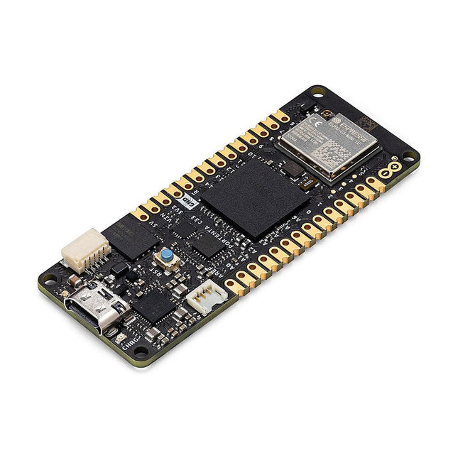
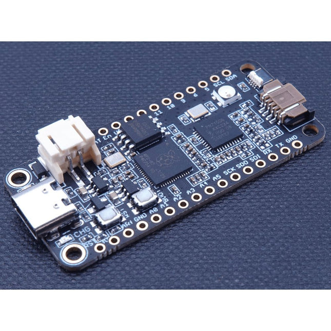
The Challenger RP2040 WiFi is a small embedded computer equipped with a WiFi module, in the popular Adafruit Feather form factor. It is based on an RP2040 microcontroller chip from the Raspberry Pi Foundation which is a dual-core Cortex-M0 that can run on a clock up to 133 MHz. The RP2040 is paired with a 8 MB high-speed flash capable of supplying data up to the max speed. The flash memory can be used both to store instructions for the microcontroller as well as data in a file system and having a file system available makes it easy to store data in a structured and easy to program approach. The device can be powered from a Lithium Polymer battery connected through a standard 2.0 mm connector on the side of the board. An internal battery charging circuit allows you to charge your battery safely and quickly. The device is shipped with a programming resistor that sets the charging current to 250 mA. This resistor can be exchanged by the user to either increase or decrease the charging current, depending on the battery that is being used. The WiFi section on this board is based on the Espressif ESP8285 chip which basically is a ESP8266 with 1 MB flash memory integrated onto the chip making it a complete WiFi only requiring very few external components. The ESP8285 is connected to the microcontroller using a UART channel and the operation is controlled using a set of standardized AT-commands. Specifications Microcontroller RP2040 from Raspberry Pi (133 MHz dual-core Cortex-M0) SPI One SPI channel configured I²C One I²C channel configured UART One UART channel configured (second UART is for the WiFi chip) Analog inputs 4 analog input channels WLAN controller ESP8285 from Espressif (160 MHz single-core Tensilica L106) Flash memory 8 MByte, 133 MHz SRAM memory 264 KByte (divided into 6 banks) USB 2.0 controller Up to 12 MBit/s full speed (integrated USB 1.1 PHY) JST Battery connector 2.0 mm pitch Onboard LiPo charger 250 mA standard charge current Onboard NeoPixel LED RGB LED Dimensions 51 x 23 x 3,2 mm Weight 9 g Downloads Datasheet Design files Product errata
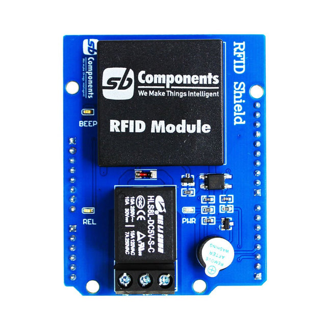
Designed with convenience and security in mind, the Ardi RFID Shield is based on the EM-18 module, operating at a frequency of 125 KHz. This shield allows you to easily integrate RFID (Radio Frequency Identification) technology into your projects, enabling seamless identification and access control systems.
Equipped with a powerful 1-channel optoisolated relay, the Ardi RFID Shield offers a reliable switching solution with a maximum DC rating of 30 V and 10 A, as well as an AC rating of 250 V and 7 A. Whether you need to control lights, motors, or other high-power devices, this shield provides the necessary functionality.
Additionally, the Ardi RFID Shield features an onboard buzzer that can be utilized for audio feedback, allowing for enhanced user interaction and system feedback. With the onboard 2-indication LEDs, you can easily monitor the status of RFID card detection, power supply, and relay activation, providing clear visual cues for your project's operation.
Compatibility is key, and the Ardi RFID Shield ensures seamless integration with the Arduino Uno platform. Paired with a read-only RFID module, this shield opens up a world of possibilities for applications such as access control systems, attendance tracking, inventory management, and more.
Features
Onboard 125 kHz EM18 RFID small, compact module
Onboard High-quality relays Relay with Screw terminal and NO/NC interfaces
Shield compatible with both 3.3 V and 5 V MCU
Onboard 3 LEDs power, relay ON/OFF State and RFID Scan status
Multi-tone Buzzer onboard for Audio alerts
Mounts directly onto ArdiPi, Ardi32 or other Arduino compatible boards
Specifications
RFID operating Frequency: 125 kHz
Reading distance: 10 cm, depending on TAG
Integrated Antenna
Relay Max Switching Voltage: 250 V AC/30 V DC
Relay Max Switching Current: 7 A/10 A
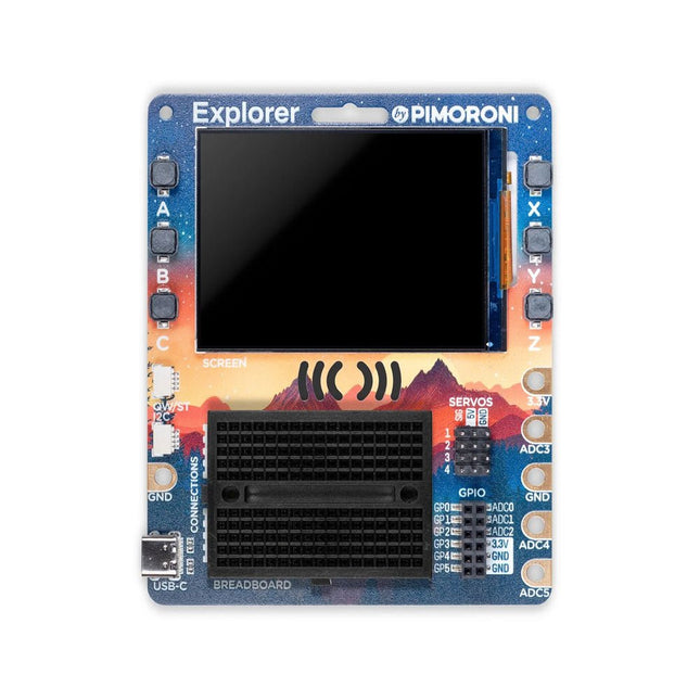
De Pimoroni Explorer Starter Kit is een elektronische avonturenspeeltuin voor fysiek computergebruik, gebaseerd op de RP2350-chip. Het bevat een 2,8-inch LCD-scherm, een luidspreker, een mini-breadboard en nog veel meer. Het is ideaal voor knutselen, experimenteren en het bouwen van kleine prototypes.
Kenmerken
Mini-breadboard voor het aansluiten van componenten
Servoheaders
Analoge ingangen
Ingebouwde luidspreker
Veel algemene invoer/uitvoer
Connectoren voor het bevestigen van krokodillensnoeren
Qw/ST-connectoren voor het bevestigen van I²C-breakouts
Specificaties
Aangedreven door RP2350B (Dual Arm Cortex-M33 met een snelheid tot 150 MHz met 520 KB SRAM)
16 MB QSPI-flash met ondersteuning voor XiP
2,8" IPS LCD-scherm (320 x 240 pixels)
Stuurprogramma-IC: ST7789V
Helderheid: 250 cd/m²
Actief gebied: 43,2 x 57,5 mm
USB-C-connector voor programmeren en voeding
Mini-broodplank
Piezo-luidspreker
6x door de gebruiker bestuurbare schakelaars
Reset- en opstartknoppen
Gemakkelijke toegang tot GPIO-headers (6x GPIO's en 3x ADC's, plus 3,3 V voeding en aarde)
6x krokodillenklemterminals (3x ADC's, plus 3,3 V stroom en aarding)
4x 3-pins servo-uitgangen
2x Qw/ST (Qwiic/STEMMA QT)-connector
2-pins JST-PH-connector voor het toevoegen van een batterij
Gleuf voor sleutelkoord!
Inclusief 2x bureaustandaardvoeten
Volledig gemonteerd (solderen niet nodig)
Programmeerbaar met C/C++ of MicroPython
Inbegrepen
1x Pimoroni Explorer
1x Multi-Sensor Stick – een fraaie nieuwe alles-in-één supersensorsuite voor omgevings-, licht- en bewegingsdetectie
Selectie van verschillende gekleurde LED's om mee te knipperen (inclusief rood, geel, groen, blauw, wit en RGB)
1x Potentiometer (voor analoog amusement)
3x 12 mm schakelaars met verschillende gekleurde kapjes
2x Servo's met continue rotatie
2x 60 mm wielen voor bevestiging aan uw servo's
1x AAA-batterijhouder (batterijen niet inbegrepen)
1x klittenband om de batterijhouder aan de achterkant van de Explorer te bevestigen
20x pin-naar-pin- en 20x pin-naar-socket-jumperdraden voor het maken van verbindingen op uw breadboard
1x Qw/ST-kabel om de Multi-Sensor Stick aan te sluiten
1x Siliconen USB-C kabel
Downloads
GitHub
Schematic
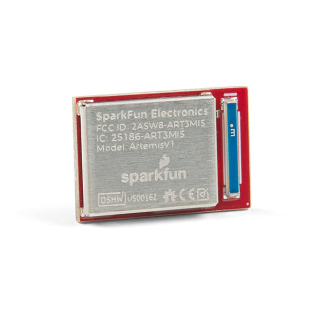
De flexibiliteit van de Artemis module start met SparkFun's Arduino core. Je kunt de Artemis module programmeren en gebruiken net zoals je dat met een Uno of een andere Arduino zou doen. De tijd om voor het eerst te knipperen is slechts 5 minuten verwijderd! We hebben de kern vanaf de grond opgebouwd, om hem snel en zo licht mogelijk te maken.Dan de module zelf. Met een afmeting van 10 mm x 15 mm heeft de Artemis module alle ondersteunende schakelingen die je nodig hebt om de fantastische Ambiq Apollo3 processor te gebruiken in je volgende project. We zijn er trots op te kunnen zeggen dat de SparkFun Artemis module de eerste open-source hardware module is waarvan de ontwerp bestanden vrij en gemakkelijk beschikbaar zijn. We hebben de module zorgvuldig ontworpen zodat het implementeren van Artemis in uw ontwerp gedaan kan worden met low-cost 2-layer PCBs en 8mil trace/space.Gemaakt in de USA bij SparkFun's Boulder productielijn, is de Artemis module ontworpen voor consumer-grade producten. Dit onderscheidt de Artemis echt van zijn Arduino broeders. Klaar om uw product te schalen? De Artemis groeit met u mee buiten de Uno footprint en Arduino IDE. Bovendien, de Artemis heeft een geavanceerde HAL (hardware abstractie laag), waardoor gebruikers de moderne Cortex-M4F architectuur tot het uiterste kunnen drijven.De SparkFun Artemis Module is volledig FCC / IC / CE gecertificeerd en is beschikbaar in volledige tape en haspel hoeveelheden. Met 1M flash en 384k RAM, heb je genoeg ruimte voor je code. De Artemis module draait op 48MHz met een 96MHz turbo mode beschikbaar en met Bluetooth om op te starten!
Onboard each moto:bit are multiple I/O pins, as well as a vertical Qwiic connector, capable of hooking up servos, sensors and other circuits. At the flip of the switch, you can get your micro:bit moving! The moto:bit connects to the micro:bit via an updated SMD, edge connector at the top of the board, making setup easy. This creates a handy way to swap out micro:bits for programming while still providing reliable connections to all of the different pins on the micro:bit. We have also included a basic barrel jack on the moto:bit that is capable of providing power to anything you connect to the carrier board. Features More reliable Edge connector for easy use with the micro:bit Full H-Bridge for control of two motors Control servo motors Vertical Qwiic Connector I²C port for extending functionality Power and battery management onboard for the micro:bit
De Portenta C33 is een krachtige System-on-Module, ontworpen voor goedkope Internet of Things (IoT) toepassingen. Hij is gebaseerd op de R7FA6M5BH2CBG microcontroller van Renesas, heeft dezelfde afmetingen als de Portenta H7, en is ook backward compatible daarmee. Hierdoor is hij volledig compatibel met alle shields en carriers uit de Portenta familie, met gebruik daarbij van zijn high-density aansluitingen. Met zijn lage kosten is de Portenta C33 is een uitstekende keuze voor ontwikkelaars die met een beperkt budget IoT apparaten en toepassingen willen maken. Of u nu een smarthome apparaat of een online industriële sensor bouwt, de Portenta C33 biedt de rekenkracht en connectiviteitsopties die nodig zijn om de klus te klaren. Het snel implementeren van AI-gestuurde projecten kan vlot en eenvoudig met de Portenta C33. Er kan gebruik worden gemaakt van een breed scala aan kant-en-klaar beschikbare software libraries en Arduino sketches, evenals widgets, die gegevens realtime weergeven op Arduino IoT Cloud gebaseerde dashboards. Kenmerken Ideaal voor goedkope IoT-toepassingen met wifi / Bluetooth LE connectiviteit Ondersteunt MicroPython en andere hoogwaardige programmeertalen Biedt beveiliging van industriële kwaliteit op hardware niveau, en veilige OTA firmware-updates Maakt gebruik van kant-en-klare software libraries en Arduino sketches Perfect geschikt om realtime gegevens te bewaken en weer te geven op Arduino IoT Cloud widget-gebaseerde dashboards Compatibel met de Arduino Portenta en MKR familie Voorzien van castellaties voor automatische assemblagelijnen Kosteneffectief presteren Met een betrouwbaarheid, veiligheid en rekenkracht die in zijn klasse niet misstaat is de Portenta C33 geschikt om veel grote en kleine bedrijven de mogelijkheid te bieden aan de slag te gaan met IoT, en zo te profiteren van een hoger niveau van efficiëntie en automatisering. Toepassingen De Portenta C33 brengt meer toepassingen dan ooit binnen het bereik van gebruikers. Van het mogelijk maken van snelle plug-and-play prototyping tot het bieden van een kosteneffectieve oplossing voor projecten op industriële schaal. Industriële IoT-gateway Machine monitoring om OEE/OPE te kunnen volgen Inline kwaliteitscontrole en -borging Monitoring van energieverbruik Aansturing van apparaten Kant-en-klare oplossing voor IoT-prototyping Specificaties Microcontroller Renesas R7FA6M5BH2CBG ARM Cortex-M33: ARM Cortex-M33 core tot 200 MHz 512 kB SRAM ingebouwd 2 MB ingebouwde Flash Arm TrustZone Secure Crypto Engine 9 Extern geheugen 16 MB QSPI Flash USB-C USB-C High Speed Connectiviteit 100 MB Ethernet interface (PHY) Wifi Bluetooth Low Energy Interfaces CAN SD-kaart ADC GPIO SPI I²S I²C JTAG/SWD Security NXP SE050C2 Secure Element Bedrijfstemperatuur -40 tot +85 °C (-40 tot 185 °F) Afmetingen 66,04 x 25,40 mm Downloads Datasheet Schema
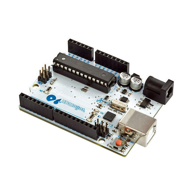
Het ATmega328 Uno Development Board (compatibel met Arduino Uno) is een microcontrollerbord gebaseerd op de ATmega328.
Hij heeft 14 digitale in-/uitgangspinnen (waarvan 6 kunnen worden gebruikt als PWM-uitgangen), 6 analoge ingangen, een 16 MHz keramische resonator, een USB-aansluiting, een stroomaansluiting, een ICSP-header en een resetknop.
Het bevat alles wat nodig is om de microcontroller te ondersteunen; sluit hem aan op een computer met een USB-kabel of voorzie hem van stroom met een AC-naar-DC-adapter of batterij om aan de slag te gaan.
Specificaties
Microcontroller
ATmega328
Bedrijfsspanning
5 V gelijkstroom
Ingangsspanning (aanbevolen)
7-12 V gelijkstroom
Ingangsspanning (limieten)
6-20 V gelijkstroom
Digitale I/O-pinnen
14 (waarvan 6 PWM-uitvoer leveren)
Analoge ingangspinnen
6
SRAM
2 kB (ATmega328)
EEPROM
1 kB (ATmega328)
Flash-geheugen
32 kB (ATmega328) waarvan 0,5 kB gebruikt door bootloader
Kloksnelheid
16 MHz
Downloads
Manual
Deze ultrasone afstandssensor (ME007-ULA V1) biedt hoge prestaties met een robuuste, waterdichte sonde. De sensor werkt volgens het principe van ultrasone echobereik en bepaalt de afstand tot een doel door de tijd te meten die is verstreken tussen het verzenden van een puls en het ontvangen van de echo. Dankzij het contactloze ontwerp kan hij een breed scala aan materialen detecteren, waaronder transparante of non-ferro voorwerpen, metalen, niet-metalen, vloeistoffen, vaste stoffen en poeders.
Specificaties
Afstand detecteren
27~800 cm
Uitvoerinterface
RS232, spanning analoog
Bedrijfsspanning
5-12 V
Gemiddelde stroom
<10 mA
Bedrijfstemperatuur
−15~60°C
Afmetingen
60 x 43 x 31 mm
De SparkFun RP2350 Pro Micro biedt een krachtig ontwikkelingsplatform, gebouwd rond de RP2350-microcontroller. Dit bord maakt gebruik van de bijgewerkte Pro Micro-vormfactor. Het bevat een USB-C-connector, Qwiic-connector, WS2812B adresseerbare RGB-LED, opstart- en resetknoppen, opnieuw instelbare PTC-zekering en PTH- en gekartelde soldeerpads.
De RP2350 is een unieke dual-core microcontroller met twee ARM Cortex-M33-processors en twee Hazard3 RISC-V-processors, allemaal draaiend op maximaal 150 MHz! Dit betekent niet dat de RP2350 een quad-core microcontroller is. In plaats daarvan kunnen gebruikers selecteren welke twee processors tijdens het opstarten moeten worden uitgevoerd. U kunt twee processors van hetzelfde type of één van elk gebruiken. De RP2350 beschikt ook over 520 kB SRAM in tien banken, een groot aantal randapparatuur, waaronder twee UART's, twee SPI- en twee I²C-controllers, en een USB 1.1-controller voor host- en apparaatondersteuning.
De Pro Micro bevat ook twee uitgebreide geheugenopties: 16 MB externe Flash en 8 MB PSRAM aangesloten op de QSPI-controller van de RP2350. De RP2350 Pro Micro werkt met C/C++ met behulp van de Pico SDK-, MicroPython- en Arduino-ontwikkelomgevingen.
Kenmerken
RP2350-microcontroller
8 MB PSRAM
16 MB Flash
Voedingsspanning
USB: 5 V
RAW: 5,3 V (max.)
Pro Micro Pinout
2x UART
1x SPI
10x GPIO (4 gebruikt voor UART1 en UART0)
4x analoog
USB-C-connector
USB 1.1 host-/apparaatondersteuning
Qwiic-connector
Knoppen
Reset
Boot
LED's
WS2812 Adresseerbare RGB-LED
Rode voedings-LED
Afmetingen: 33 x 17,8 mm
Downloads
Schematic
Eagle Files
Board Dimensions
Hookup Guide
RP2350 MicroPython Firmware (Beta 04)
SparkFun Pico SDK Library
Arduino Pico Arduino Core
Datasheet (RP2350)
Datasheet (APS6404L PSRAM)
RP2350 Product Brief
Raspberry Pi RP2350 Microcontroller Documentation
Qwiic Info Page
GitHub Repository
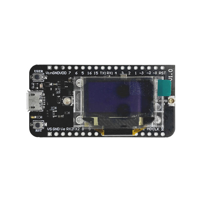
The CubeCell series is designed primarily for LoRa/LoRaWAN node applications.
Built on the ASR605x platform (ASR6501, ASR6502), these chips integrate the PSoC 4000 series MCU (ARM Cortex-M0+ Core) with the SX1262 module. The CubeCell series offers seamless Arduino compatibility, stable LoRaWAN protocol operation, and straightforward connectivity with lithium batteries and solar panels.
The HTCC-AB02S is a developer-friendly board with an integrated AIR530Z GPS module, ideal for quickly testing and validating communication solutions.
Features
Arduino compatible
Based on ASR605x (ASR6501, ASR6502), those chips are already integrated the PSoC 4000 series MCU (ARM Cortex M0+ Core) and SX1262
LoRaWAN 1.0.2 support
Ultra low power design, 21 uA in deep sleep
Onboard SH1.25-2 battery interface, integrated lithium battery management system (charge and discharge management, overcharge protection, battery power detection, USB/battery power automatic switching)
Good impendence matching and long communication distance
Onboard solar energy management system, can directly connect with a 5.5~7 V solar panel
Micro USB interface with complete ESD protection, short circuit protection, RF shielding, and other protection measures
Integrated CP2102 USB to serial port chip, convenient for program downloading, debugging information printing
Onboard 0.96-inch 128x64 dot matrix OLED display, which can be used to display debugging information, battery power, and other information
Using Air530 GPS module with GPS/Beidou Dual-mode position system support
Specifications
Main Chip
ASR6502 (48 MHz ARM Cortex-M0+ MCU)
LoRa Chipset
SX1262
Frequency
863~870 MHz
Max. TX Power
22 ±1 dBm
Max. Receiving Sensitivity
−135 dBm
Hardware Resource
2x UART1x SPI2x I²C1x SWD3x 12-bit ADC input8-channel DMA engine16x GPIO
Memory
128 Kb FLASH16 Kb SRAM
Power consumption
Deep sleep 21 uA
Interfaces
1x Micro USB1x LoRa Antenna (IPEX)2x (15x 2.54 Pin header) + 3x (2x 2.54 Pin header)
Battery
3.7 V lithium battery (power supply and charging)
Solar Energy
VS pin can be connected to 5.5~7 V solar panel
USB to Serial Chip
CP2102
Display
0.96" OLED (128 x 64)
Operating temperature
−20~70°C
Dimensions
55.9 x 27.9 x 9.5 mm
Included
1x CubeCell HTCC-AB02S Development Board
1x Antenna
1x 2x SH1.25 battery connector
Downloads
Datasheet
Schematic
GPS module (Manual)
Quick start
GitHub
Features Volgt CAN V2.0B tot 1 Mb/s Industriële standaard 9 pins sub-D connector OBD-II en CAN standaard pinout selecteerbaar. Verwisselbare chip select pin Verwisselbare CS pin voor TF-kaartslot Verwisselbare INT pin Schroef terminal die gemakkelijk aan te sluiten CAN_H en CAN_L Arduino Uno pin headers Micro SD kaarthouder 2 Grove connectoren (I2C en UART) SPI-interface tot 10 MHz Standaard (11 bit) en uitgebreide (29 bit) data en remote frames Twee ontvangstbuffers met geprioriteerde berichtopslag
Pico Breakout Garden Base sits underneath your Pico and lets you connect up to six of our extensive selection of Pimoroni breakouts to it. Whether it's environmental sensors so you can keep track of the temperature and humidity in your office, a whole host of little screens for important notifications and readouts, and, of course, LEDs. Scroll down for a list of breakouts that are currently compatible with our C++/MicroPython libraries!As well as a labelled landing area for your Pico, there's also a full set of broken out Pico connections, in case you need to attach even more sensors, wires, and circuitry. We've thrown in some rubber feet to keep the base nice and stable and to stop it from scratching your desk, or there are M2.5 mounting holes at the corners so that you can bolt it onto a solid surface if you prefer.The six sturdy black slots are edge connectors that connect the breakouts to the pins on your Pico. There's two slots for SPI breakouts, and four slots for I²C breakouts. Because I²C is a bus, you can use multiple I²C devices at the same time, providing they don't have the same I²C address (we've made sure that all of our breakouts have different addresses, and we print them on the back of the breakouts so they're easy to find).As well as being a handy way to add functionality to your Pico, Breakout Garden is also very useful for prototyping projects without the need for complicated wiring, soldering, or breadboards, and you can grow or change up your setup at any time.Features
Six sturdy edge-connector slots for breakouts
4x I²C slots (5 pins)
2x SPI slot (7 pins)
Landing area with female headers for Raspberry Pi Pico
0.1” pitch, 5 or 7 pin connectors
Broken-out pins
Reverse polarity protection (built into breakouts)
99% assembled – just need to stick on the feet!
Compatible with Raspberry Pi Pico
Grove-Servo is a rotary actuator that allows for precise control of the angular position. It's suitable for use in closed-loop systems where precise position control is needed. We regulated the three-wire servo into a Grove standard connecter. You can plug and play it as a typical Grove module now, without jumper wires clutter.
Features
High Accuracy: closed-loop control of position, speed and torque is achieved
High Stability: stable operation at a low speed of 0.12/0.16s/60°
Easy to use: compatible with Grove port, just plug-and-play
Features Integrated Cold-Junction Compensation Supported Types (designated by NIST ITS-90): Type K, J, T, N, S, E, B and R Four Programmable Temperature Alert Outputs: Monitor Hot- or Cold-Junction Temperatures Detect rising or falling temperatures Up to 255°C of Programmable Hysteresis Programmable Digital Filter for Temperature Low Power Dimensions: 20 mm x 40 mm x 18 mm Weight: 18 g Application Petrochemical Thermal Management Hand-Held Measurement Equipment Industrial Equipment Thermal Management Ovens Industrial Engine Thermal Monitor Temperature Detection Racks Downloads Eagle Files Github library Datasheet
The Challenger RP2040 NFC is a small embedded computer, equipped with an advanced on-board NFC controller (NXP PN7150), in the popular Adafruit Feather form factor. It is based on an RP2040 microcontroller chip from the Raspberry Pi Foundation which is a dual-core Cortex-M0 that can run on a clock up to 133 MHz. NFC The PN7150 is a full featured NFC controller solution with integrated firmware and NCI interface designed for contactless communication at 13.56 MHz. It is fully compatible with NFC forum requirements and is greatly designed based on learnings from previous NXP NFC device generation. It is the ideal solution for rapidly integrating NFC technology in any application, especially small embedded systems reducing Bill of Material (BOM). The integrated design with full NFC forum compliancy gives the user all the following features: Embedded NFC firmware providing all NFC protocols as pre-integrated feature. Direct connection to the main host or microcontroller, by I²C-bus physical and NCI protocol. Ultra-low power consumption in polling loop mode. Highly efficient integrated power management unit (PMU) allowing direct supply from a battery. Specifications Microcontroller RP2040 from Raspberry Pi (133 MHz dual-core Cortex-M0) SPI One SPI channels configured I²C Two I²C channel configured (dedicated I²C for the PN7150) UART One UART channel configured Analog inputs 4 analog input channels NFC module PN7150 from NXP Flash memory 8 MB, 133 MHz SRAM memory 264 KB (divided into 6 banks) USB 2.0 controller Up to 12 MBit/s full speed (integrated USB 1.1 PHY) JST Battery connector 2.0 mm pitch On board LiPo charger 450 mA standard charge current Dimensions 51 x 23 x 3,2 mm Weight 9 g Note: Antenna is not included. Downloads Datasheet Quick start example
De fingerprintsensor module R301T kan dankzij deze geïntegreerde chip beelden verzamelen en algoritmes berekenen. Een andere opmerkelijke functie van de sensor is, dat hij de vingerafdruk kan herkennen in verschillende omstandigheden, bijvoorbeeld vochtigheid, lichttextuur of veranderingen van de huid. Dit biedt een zeer breed scala aan mogelijke toepassingen om onder andere sloten en deuren te beveiligen. De chip kan gegevens versturen via UART, seriele TTLl en USB naar de aangesloten controller. Specificaties Model JP2000 sensor Chip 32 Bit ARM Cortex-M3 Chip opslag 96 kB RAM, 1 MB Flash Voeding 4.2 - 6.0 V Stroomverbruik Typical: 40 mAPiek: 50 mA Logica 3,3 / 5 V TTL Logica Fingerprint opslag capaciteit 3000 Herkenningsmode 1:N Identificatie1:1 Verificatie Instelbaar veiligheidsniveau 1 - 5 niveaus(standaard veiligheidsniveau: 3) Fout acceptatie percentage < 0.001%(op veiligheidsniveau 3) Fout acceptatie percentage < 0.1%(op veiligheidsniveau 3) Reactie tijd Voorbehandeling: < 0.45 sHerkenning: < 1.5 s Baudrate 9600 - 921600 UART communicatie No parity, Stop Bit: 1 Afmetingen 42 x 19 x 8 mm Inbegrepen 1x Fingerprint sensor COM-FP-R301T 1x Kabel Downloads Datasheet Gebruiksaanwijzing
THSER102 is a plug-and-play cable extension kit for Raspberry Pi Camera Modules. The kit is compatible with Raspberry Pi Camera Module 3, in addition to Camera V2 (version 2.1), HQ/Global Shutter Camera, and defined modes of the Raspberry Pi Camera Module V1.3.
The THSER102 extends the cable length for >10 meters between the Raspberry Pi Camera Module and the Computer with a standard LAN Cable.
There is no need for software or coding. THSER102 works as if the Raspberry Pi Camera were directly connected to the computer.
The THSER102 also supports advanced applications. HAT on HAT support allows to use another HAT board on top of THSER102 Rx Board. 3ch GPIO Extension allows extending GPIO communication between the camera location and the computer.
Features
Supporting all Raspberry Pi Camera Modules including Camera Module 3
>10-meter Cable Extension
Plug and Play
No software configuration is needed.
Camera works as if THSER102 not exists.
Advanced Applications Supported
HAT on HAT
3ch GPIO Extension
Included
1x Tx Board
1x Rx Board
1x LAN Cable (2 m)
2x Flat Flex Cables
1x Pin Header
6x Mounting Screws for Rx Board
3x Longer Spacers for Rx Board
4x Mounting screws for Tx Board (for Camera V2 only)
4x Shorter Spacers for Tx Board (for Camera V2 only)
4x Mounting Nuts for Tx Board (for Camera V2 only)
Downloads
Datasheet
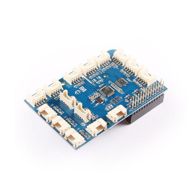
The GrovePi+ is an easy-to-use and modular system for hardware hacking with the Raspberry Pi, no need for soldering or breadboards: plug in your Grove sensors and start programming directly. Grove is an easy-to-use collection of more than 100 inexpensive plug-and-play modules that sense and control the physical world. By connecting Grove Sensors to Raspberry Pi, it empowers your Pi in the physical world. With hundreds of sensors to choose from Grove families, the possibilities for interaction are endless. Set-up in 4 simple steps Slip the GrovePi+ board over your Raspberry Pi Connect the Grove modules to the GrovePi+ board Upload your program to Raspberry Pi Begin taking in the world data Please note: Raspberry Pi board is not included
The SparkFun MicroMod mikroBUS Carrier Board takes advantage of the MicroMod, Qwiic, and mikroBUS ecosystems making it easy to rapidly prototype with each of them, combined. The MicroMod M.2 socket and mikroBUS 8-pin header provide users the freedom to experiment with any Processor Board in the MicroMod ecosystem and any Click board in the mikroBUS ecosystem, respectively. This board also features two Qwiic connectors to seamlessly integrate hundreds of Qwiic sensors and accessories into your project. The mikroBUS socket comprises a pair of 8-pin female headers with a standardized pin configuration. The pins consist of three groups of communications pins (SPI, UART and I²C), six additional pins (PWM, Interrupt, Analog input, Reset and Chip select), and two power groups (3.3 V and 5 V). While a modern USB-C connector makes programming easy, the Carrier Board is also equipped with a MCP73831 Single-Cell Lithium-Ion/Lithium-Polymer Charge IC so you can charge an attached single-cell LiPo battery. The charge IC receives power from the USB connection and can source up to 450 mA to charge an attached battery. Features M.2 MicroMod (Processor Board) Connector USB-C Connector 3.3 V 1 A Voltage Regulator 2x Qwiic Connectors mikroBUS Socket Boot/Reset Buttons Charge Circuit JTAG/SWD PTH Pins Downloads Schematic Eagle Files Board Dimensions Hookup Guide Getting Started with Necto Studio mikroBUS Standard Qwiic Info Page GitHub Hardware Repo
The DiP-Pi WiFi Master is an Advanced WiFi connectivity System with sensors embedded interfaces that cover most of possible needs for IoT application based on Raspberry Pi Pico. It is powered directly from the Raspberry Pi Pico VBUS. The DiP-Pi WiFi Master contains Raspberry Pi Pico embedded RESET button as also ON/OFF Slide Switch that is acting on Raspberry Pi Pico Power Sources.The DiP-Pi WiFi Master is equipped with WiFi ESP8266 Clone module with embedded antenna. This feature open a wide range of IoT applications based on it.In Addition to all above features DiP-Pi WiFi Master is equipped with embedded 1-wire, DHT11/22 sensors, and micro–SD Card interfaces. Combination of the extended powering, battery, and sensors interfaces make the DiP-Pi WiFi Master ideal for IoT applications like data logger, plants monitoring, refrigerators monitoring etc.DiP-Pi WiFi Master is supported with plenty of ready to use examples written in Micro Python or C/C++.SpecificationsGeneral
Dimensions 21 x 51 mm
Raspberry Pi Pico pinout compatible
Independent Informative LEDs (VBUS, VSYS, V3V3)
Raspberry Pi Pico RESET Button
ON/OFF Slide Switch acting on Raspberry Pi Pico Powering Source
Embedded 3.3 V @ 600 mA LDO
ESP8266 Clone WiFi Connectivity
ESP8266 Firmware Upload Switch
Embedded 1-wire Interface
Embedded DHT-11/22 Interface
Powering OptionsRaspberry Pi Pico micro-USB (via VBUS)Embedded Peripherals and Interfaces
Embedded 1-wire interface
Embedded DHT-11/22 Interface
Micro SD Card Socket
Programmer Interface
Standard Raspberry Pi Pico C/C++
Standard Raspberry Pi Pico Micro Python
Case CompatibilityDiP-Pi Plexi-Cut CaseInformative LEDs
VB (VUSB)
VS (VSYS)
V3 (V3V3)
System Protection
Direct Raspberry Pi Pico Hardware Reset Button
PPTC 500 mA @ 18 V fuse on EPR
EPR/LDO Over Temperature protection
EPR/LDO Over Current protection
System Design
Designed and Simulated with PDA Analyzer with one of the most advanced CAD/CAM Tools – Altium Designer
Industrial Originated
PCB Construction
2 ozcopper PCB manufactured for proper high current supply and cooling
6 mils track/6 mils gap technology 2 layers PCB
PCB Surface Finishing – Immersion Gold
Multi-layer Copper Thermal Pipes for increased System Thermal Response and better passive cooling
Downloads
Datasheet
Manual