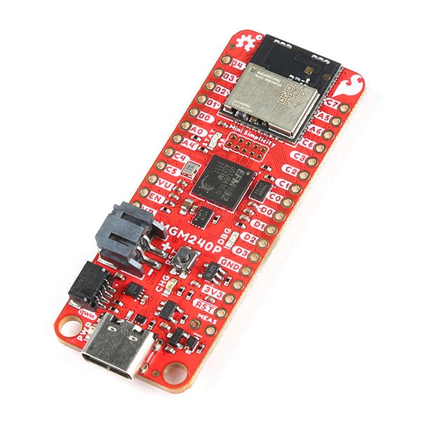
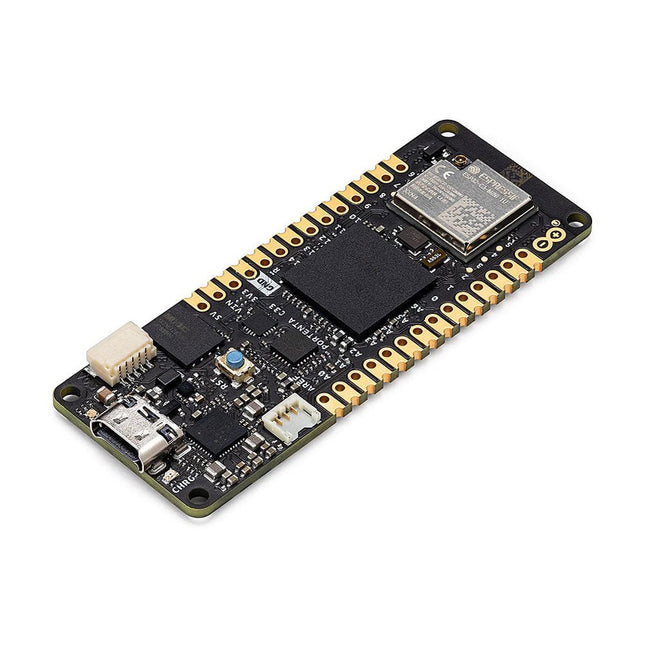
The SparkFun Thing Plus Matter is the first easily accessible board of its kind that combines Matter and SparkFun’s Qwiic ecosystem for agile development and prototyping of Matter-based IoT devices. The MGM240P wireless module from Silicon Labs provides secure connectivity for both 802.15.4 with Mesh communication (Thread) and Bluetooth Low Energy 5.3 protocols. The module comes ready for integration into Silicon Labs' Matter IoT protocol for home automation.
What is Matter? Simply put, Matter allows for consistent operation between smart home devices and IoT platforms without an Internet connection, even from different providers. In doing so, Matter is able to communicate between major IoT ecosystems in order to create a single wireless protocol that is easy, reliable, and secure to use.
The Thing Plus Matter (MGM240P) includes Qwiic and LiPo battery connectors, and multiple GPIO pins capable of complete multiplexing through software. The board also features the MCP73831 single-cell LiPo charger as well as the MAX17048 fuel gauge to charge and monitor a connected battery. Lastly, a µSD card slot for any external memory needs is integrated.
The MGM240P wireless module is built around the EFR32MG24 Wireless SoC with a 32-bit ARM Cortext-M33 core processor running at 39 MHz with 1536 kb Flash memory and 256 kb RAM. The MGM240P works with common 802.15.4 wireless protocols (Matter, ZigBee, and OpenThread) as well as Bluetooth Low Energy 5.3. The MGM240P supports Silicon Labs' Secure Vault for Thread applications.
Specifications
MGM240P Wireless Module
Built around the EFR32MG24 Wireless SoC
32-bit ARM-M33 Core Processor (@ 39 MHz)
1536 kB Flash Memory
256 kB RAM
Supports Multiple 802.15.4 Wireless Protocols (ZigBee and OpenThread)
Bluetooth Low Energy 5.3
Matter-ready
Secure Vault Support
Built-in Antenna
Thing Plus Form-Factor (Feather-compatible):
Dimensions: 5.8 x 2.3 cm (2.30 x 0.9")
2 Mounting Holes:
4-40 screw compatible
21 GPIO PTH Breakouts
All pins have complete multiplexing capability through software
SPI, I²C and UART interfaces mapped by default to labeled pins
13 GPIO (6 labeled as Analog, 7 labeled for GPIO)
All function as either GPIO or Analog
Built-in-Digital to Analog Converter (DAC)
USB-C Connector
2-Pin JST LiPo Battery Connector for a LiPo Battery (not included)
4-Pin JST Qwiic Connector
MC73831 Single-Cell LiPo Charger
Configurable charge rate (500 mA Default, 100 mA Alternate)
MAX17048 Single-Cell LiPo Fuel Gauge
µSD Card Slot
Low Power Consumption (15 µA when MGM240P is in Low Power Mode)
LEDs:
PWR – Red Power LED
CHG – Yellow battery charging status LED
STAT – Blue status LED
Reset Button:
Physical push-button
Reset signal can be tied to A0 to enable use as a peripheral device
Downloads
Schematic
Eagle Files
Board Dimensions
Hookup Guide
Datasheet (MGM240P)
Fritzing Part
Thing+ Comparison Guide
Qwiic Info Page
GitHub Hardware Repo
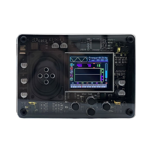
De Mixer Geek Theremin+ is een leuk en innovatief elektronisch muziekinstrument, geïnspireerd op de klassieke theremin. In tegenstelling tot traditionele instrumenten wordt de Theremin+ bespeeld zonder fysiek contact, waarbij de toonhoogte en het volume worden geregeld met handbewegingen in de lucht.
De Theremin+ biedt een spannende en praktische manier om muziek te ontdekken en met geluid te experimenteren.
Kenmerken
Klaar voor gebruik direct uit de doos
Uitgerust met een luidspreker en een kleurenscherm
Intuïtieve navigatie en bevestiging met knoppen
Kies uit meer dan 70 tonen
Meerdere aanpasbare functie-instellingen
Geeft golfvorm, tijd, frequentie, volume en bijbehorende pianotoonhoogte weer (display kan worden uitgeschakeld)
Aangedreven via USB-C poort; compatibel met powerbanks
Compact ontwerp met afneembare telescopische antenne voor eenvoudige opslag
Maakt verbinding met een hoofdtelefoon, externe luidsprekers of opnameapparatuur
Afmetingen: 98 x 70 x 18 mm
Inbegrepen
1x Theremin+ muziekinstrument
2x Antennes
1x USB-C-kabel
Features
324x324 pixels camerasensor: gebruik een van de kernen in Portenta om beeldherkenningsalgoritmes uit te voeren met de OpenMV for Arduino editor
100 Mbps Ethernet connector: verbind uw Portenta H7 met het bekabelde Internet
2 onboard microfoons voor richtingsgevoelige geluidsdetectie: vang en analyseer geluid in real-time
JTAG connector: voer low-level debugging uit van uw Portenta bord of speciale firmware updates met behulp van een externe programmer
SD-Card aansluiting: sla uw vastgelegde gegevens op de kaart op, of lees configuratiebestanden
Het Vision Shield is ontworpen om bovenop de Arduino Portenta familie te passen. De Portenta boards zijn voorzien van multicore 32-bit ARM® Cortex™ processoren die draaien op honderden megahertz, met megabytes aan programmageheugen en RAM. Portenta boards worden geleverd met WiFi en Bluetooth.Embedded computer vision gemakkelijk gemaaktArduino heeft samengewerkt met OpenMV om u een gratis licentie voor de OpenMV IDE aan te bieden, een eenvoudige manier om computervisie te gebruiken met MicroPython als programmeerparadigma. Download de OpenMV voor Arduino Editor van onze professionele tutorials site en blader door de voorbeelden die we voor u hebben voorbereid in de OpenMV IDE. Bedrijven over de hele wereld bouwen al hun commerciële producten op basis van deze eenvoudig-maar-krachtige benadering voor het detecteren, filteren en classificeren van afbeeldingen, QR-codes, en anderen. Debugging met professioneel gereedschapSluit uw Portenta H7 aan op een professionele debugger via de JTAG connector. Gebruik professionele software tools zoals die van Lauterbach of Segger bovenop uw board om uw code stap voor stap te debuggen. Het Vision Shield maakt de benodigde pinnen vrij voor het aansluiten van uw externe JTAG.
Camera
Himax HM-01B0 cameramodule
Resolutie
320 x 320 actieve pixel resolutie met ondersteuning voor QVGA
beeldsensor
Hoge gevoeligheid 3.6? BrightSense™ pixel technologie
Microfoon
2 x MP34DT05
Lengte
66 mm
Breedte
25 mm
Gewicht
11 gr
Voor meer informatie, bekijk de tutorials die door Arduino hier.
At the core of this module is ESP32-S2, an Xtensa® 32-bit LX7 CPU that operates at up to 240 MHz. The chip has a low-power co-processor that can be used instead of the CPU to save power while performing tasks that do not require much computing power, such as monitoring of peripherals. ESP32-S2 integrates a rich set of peripherals, ranging from SPI, I²S, UART, I²C, LED PWM, TWAITM, LCD, Camera interface, ADC, DAC, touch sensor, temperature sensor, as well as up to 43 GPIOs. It also includes a full-speed USB On-The-Go (OTG) interface to enable USB communication.FeaturesMCU
ESP32-S2 embedded, Xtensa® single-core 32-bit LX7 microprocessor, up to 240 MHz
128 KB ROM
320 KB SRAM
16 KB SRAM in RTC
WiFi
802.11 b/g/n
Bit rate: 802.11n up to 150 Mbps
A-MPDU and A-MSDU aggregation
0.4 µs guard interval support
Center frequency range of operating channel: 2412 ~ 2484 MHz
Hardware
Interfaces: GPIO, SPI, LCD, UART, I²C, I²S, Camera interface, IR, pulse counter, LED PWM, TWAI (compatible with ISO 11898-1), USB OTG 1.1, ADC, DAC, touch sensor, temperature sensor
40 MHz crystal oscillator
4 MB SPI flash
Operating voltage/Power supply: 3.0 ~ 3.6 V
Operating temperature range: –40 ~ 85 °C
Dimensions: 18 × 31 × 3.3 mm
Applications
Generic Low-power IoT Sensor Hub
Generic Low-power IoT Data Loggers
Cameras for Video Streaming
Over-the-top (OTT) Devices
USB Devices
Speech Recognition
Image Recognition
Mesh Network
Home Automation
Smart Home Control Panel
Smart Building
Industrial Automation
Smart Agriculture
Audio Applications
Health Care Applications
Wi-Fi-enabled Toys
Wearable Electronics
Retail & Catering Applications
Smart POS Machines
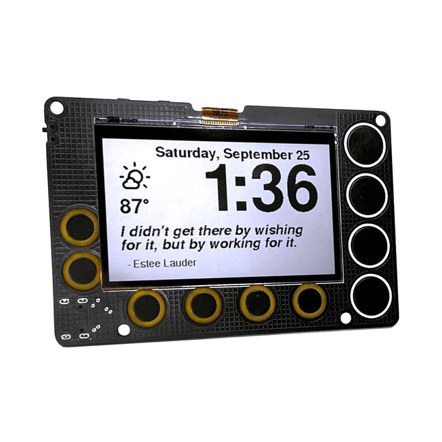
Een open source 2,7 inch IoT-scherm met laag stroomverbruik, aangestuurd door een ESP32-S2 module en voorzien van SHARP's Memory-in-Pixel (MiP) schermtechnologieDe Newt is een permanent werkend beeldscherm voor wandmontage dat op batterijen werkt , en online gaat om het weer, kalenders, sportuitslagen, to-do lijsten, notities... op te halen, eigenlijk alles wat op het internet te vinden is! Het wordt aangestuurd door een ESP32-S2 microcontroller die je kunt programmeren met Arduino, CircuitPython, MicroPython, of ESP-IDF. Het is perfect voor makers:
Sharp's Memory-in-Pixel (MiP) technologie vermijdt de trage refresh tijden van E-Ink schermen.
Een real-time klok (RTC) werd toegevoegd ter ondersteuning van timers en alarmen.
De Newt is ontworpen met batterijvoeding in gedachten; elk onderdeel op de printplaat is gekozen vanwege zijn specificaties om op een laag stroomverbruik te werken.
Newt is ontworpen om 'snoerloos' te werken, wat betekent dat hij gemonteerd kan worden op plaatsen waar een netsnoer onhandig zou zijn, bijvoorbeeld een muur, koelkast, spiegel of droogbord. Met de optionele standaard zijn bureaus, planken en nachtkastjes ook goede opties.Newt is open source, en alle ontwerpbestanden en bibliotheken zijn beschikbaar voor beoordeling, gebruik en wijziging. Dat is echter niet verplicht. Elke Newt wordt geleverd met werkende code met de volgende eigenschappen:
Actuele weerdetails
Uurlijkse en dagelijkse weersvoorspelling
Alarm
Timer
Inspirerende notities
Voorspelling luchtkwaliteit
Gewoonte kalender
Pomodoro timer
Strategiekaarten
Alleen het volgen van de instructies voor Wi-Fi voorziening is nodig om te beginnen. Er zijn geen app-downloads nodig.Specificaties
Display
Sharp Memory LCD
Scherm afmetingen
2,7 inch
Resolutie
240 x 400
Deep sleep stroomverbruik
30 uA
Verversingssnelheid
< 0.001 s
Periodieke verversing van het scherm vereist
Nee
Invoerknoppen
10 capacitieve pads, 1 drukknop
RTC inbegrepen
Ja
Luidspreker inbegrepen
Ja
Voedingsingang
USB Type-C
Batterijen inbegrepen
Nee
Programmeertalen
Arduino, CircuitPython, ESP IDF, MicroPython
Afmetingen
91 x 61 x 9 mm
Microcontroller
Espressif ESP32-S2-WROVER Module met 4 MB flash en 2 MB PSRAM
Geschikt voor Wi-Fi
Ondersteunt Arduino, MicroPython, CircuitPython en ESP-IDF
Deep sleep stroom van 25 ?A
Display
2,7-inch MiP LCD met 240 x 400 pixels
Biedt contrastrijke weergave met hoge resolutie en lage latency bij zeer laag stroomverbruik
Reflecterende modus gebruikt omgevingslicht en maakt achtergrondverlichting overbodig
Bijhouden van de tijd, timers en alarmen
Micro Crystal RV-3028-C7 RTC
Geoptimaliseerd voor extreem laag stroomverbruik (45 ?A)
Kan tegelijkertijd een periodieke timer, een afteltimer en een alarm beheren
Hardware-interrupt voor timers en alarmen
43 bytes non-volatile user memory, 2 bytes user RAM
Aparte UNIX tijdteller
BuzzerLuidspreker/zoemer met mini-klasse-D versterker op DAC-uitgang A0, kan tonen of lo-fi audioclips weergevenGebruikersinvoer
Aan/uit-schakelaar
Twee programmeerbare aanraaktoetsen voor reset en opstarten
10 capacitieve touch-pads
StroomvoorzieningNewt is ontworpen om met een 500 mAH LiPo batterij één tot twee maanden te kunnen werken tussen twee oplaadbeurten. De exacte werkingsduur varieert. (Vooral door intensief gebruik van Wi-Fi zal de batterij sneller leeg raken.)
USB Type-C connector voor programmeren, voeding en opladen
Spanningsregelaar met lage ruststroom (TOREX XC6220) die 1 A stroom kan leveren en verbruikt slechts 8 ?A in power saving mode.
JST-connector voor een Lithium-Ion batterij
Batterij-oplaadcircuit (MCP73831)
Batterij-indicator (1 ?A ruststroom)
Software
Newt hardware is compatibel met open-source Arduino bibliotheken voor ESP32-S2, Adafruit GFX (fonts), Adafruit Sharp Memory Display (display writing), en RTC RV-3028-C7 (RTC).
Arduino-bibliotheken en voorbeeldprogramma's zijn in ontwikkeling en zullen voor de lancering beschikbaar zijn in onze GitHub repository.
CircuitPython bibliotheken en registratie staan op de planning, met de ontwikkeling van een CircuitPython bibliotheek voor de RV-3028 real-time klok als belangrijke voorwaarde.
Inbegrepen
Phambili Newt – Volledig gemonteerd met voorgeïnstalleerde firmware
Lasergesneden bureaustandaard
Voetjes met mini-magneet
Benodigde schroeven
Support & Documentatie
Complete gebruikersinstructies
GitHub: Arduino Library en Codebase
GitHub: Schema van het board
Video's van prototypes of demos (de bouw is te volgen op Hackaday)
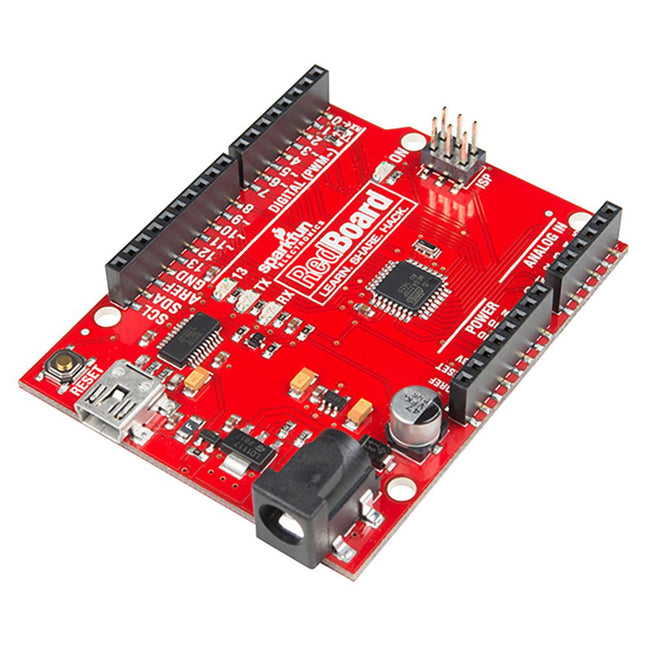
Features ATmega328 microcontroller met Optiboot (UNO) Bootloader Ingangsspanning: 7 V - 15 V 0 V - 5 V uitgangen met 3,3 V compatibele ingangen 6 analoge ingangen 14 digitale I/O-pinnen (6 PWM-uitgangen) ISP-kopbal 16 MHz kloksnelheid 32 k Flash-geheugen R3 Shield Compatible Alle SMD constructie USB programmering vergemakkelijkt door de alomtegenwoordige FTDI FT231X Rode PCB Het SparkFun RedBoard combineert de stabiliteit van de FTDI, de eenvoud van de Uno's Optiboot bootloader, en de R3 schild compatibiliteit van de Uno R3. RedBoard heeft de hardware randapparatuur die u gewend bent: 6 Analoge ingangen 14 Digitale I/O pinnen (6 PWM pinnen) SPI UART Externe interrupts Hier kunt u de nieuwste VCP-drivers voor FTDI-apparaten downloaden. Kijk ook eens naar de GitHub repository aangeboden door SparkFun.
At the core of this module is ESP32-S2, an Xtensa® 32-bit LX7 CPU that operates at up to 240 MHz. The chip has a low-power co-processor that can be used instead of the CPU to save power while performing tasks that do not require much computing power, such as monitoring of peripherals. ESP32-S2 integrates a rich set of peripherals, ranging from SPI, I²S, UART, I²C, LED PWM, TWAITM, LCD, Camera interface, ADC, DAC, touch sensor, temperature sensor, as well as up to 43 GPIOs. It also includes a full-speed USB On-The-Go (OTG) interface to enable USB communication.FeaturesMCU
ESP32-S2 embedded, Xtensa® single-core 32-bit LX7 microprocessor, up to 240 MHz
128 KB ROM
320 KB SRAM
16 KB SRAM in RTC
WiFi
802.11 b/g/n
Bit rate: 802.11n up to 150 Mbps
A-MPDU and A-MSDU aggregation
0.4 µs guard interval support
Center frequency range of operating channel: 2412 ~ 2484 MHz
Hardware
Interfaces: GPIO, SPI, LCD, UART, I²C, I²S, Camera interface, IR, pulse counter, LED PWM, TWAI (compatible with ISO 11898-1), USB OTG 1.1, ADC, DAC, touch sensor, temperature sensor
40 MHz crystal oscillator
4 MB SPI flash
Operating voltage/Power supply: 3.0 ~ 3.6 V
Operating temperature range: –40 ~ 85 °C
Dimensions: 18 × 31 × 3.3 mm
Applications
Generic Low-power IoT Sensor Hub
Generic Low-power IoT Data Loggers
Cameras for Video Streaming
Over-the-top (OTT) Devices
USB Devices
Speech Recognition
Image Recognition
Mesh Network
Home Automation
Smart Home Control Panel
Smart Building
Industrial Automation
Smart Agriculture
Audio Applications
Health Care Applications
Wi-Fi-enabled Toys
Wearable Electronics
Retail & Catering Applications
Smart POS Machines
The matte-black circuit board is extra thick and has subtle white markings, including an alphanumeric grid and PIN labels. The wiring pattern — that of classic breadboards — is easy to see by looking at the exposed traces on the bottom of the board.
The kit comes complete with the 'Integrated Circuit Leg' stand and 8 colour-coded thumbscrew terminal posts. Using the terminal posts and solder points, you can hook up to your 'IC' with bare wires, lugs, alligator clips, and/or solder joints. Connections to the 8 terminal posts are through the three-position strips on the PCB; each is labelled with the corresponding PIN.
Kenmerken
Anodized aluminium stand
8-32 size press-fit threaded inserts (8 pieces) pre-installed in the protoboard
All materials (including the circuit board and stand) are RoHS compliant (lead-free)
Tri lobular thread forming screws (6 pieces, black, 6-32 thread size) and spacers for mounting the stand.
Dimensions: 13.25 x 8.06 x 2.54 mm
Dimensions assembled: 13.25 x 9.9 x 4.3 cm
De Milk-V Duo 256M is een ultracompact embedded ontwikkelplatform gebaseerd op de SG2002-chip. Het kan Linux en RTOS draaien en biedt een betrouwbaar, goedkoop en krachtig platform voor professionals, industriële ODM's, AIoT-enthousiastelingen, doe-het-zelf-hobbyisten en makers.
Dit bord is een verbeterde versie van Duo met een geheugenboost tot 256 MB, geschikt voor toepassingen die grotere geheugencapaciteiten vereisen. De SG2002 verhoogt de rekenkracht naar 1,0 TOPS @ INT8. Het maakt naadloos schakelen tussen RISC-V/ARM-architecturen mogelijk en ondersteunt gelijktijdige werking van dubbele systemen. Bovendien bevat het een reeks rijke GPIO-interfaces zoals SPI, UART, geschikt voor een breed scala aan hardwareontwikkelingen op het gebied van intelligente monitoring, waaronder IP-camera's, slimme kijkgaatjes, visuele deurbellen en meer.
SG2002 is een krachtige chip met laag vermogen, ontworpen voor verschillende productgebieden, zoals intelligente IP-bewakingscamera's, slimme deursloten, visuele deurbellen en huisintelligentie. Het integreert H.264-videocompressie en -decodering, H.265-videocompressiecodering en ISP-mogelijkheden. Het ondersteunt meerdere beeldverbeterings- en correctie-algoritmen, zoals HDR breed dynamisch bereik, 3D-ruisonderdrukking, ontwaseming en lensvervormingscorrectie, waardoor klanten professionele videobeeldkwaliteit krijgen.
De chip bevat ook een zelfontwikkelde TPU, die 1,0 TOPS aan rekenkracht levert bij 8-bit integer-bewerkingen. De speciaal ontworpen TPU-planningsengine zorgt op efficiënte wijze voor een gegevensstroom met hoge bandbreedte voor alle kernen van de tensorverwerkingseenheden. Bovendien biedt het gebruikers een krachtige deep learning-modelcompiler en software-SDK-ontwikkelkit. Toonaangevende deep learning-frameworks zoals Caffe en Tensorflow kunnen eenvoudig naar het platform worden geporteerd. Bovendien omvat het security boot, veilige updates en encryptie, waardoor een reeks beveiligingsoplossingen wordt geboden, van ontwikkeling, massaproductie tot producttoepassingen.
De chip integreert een 8-bit MCU-subsysteem, dat de typische externe MCU vervangt om kostenbesparingen en energie-efficiëntiedoelen te bereiken.
Specificaties
SoC
SG2002
RISC-V CPU
C906 @ 1 Ghz + C906 @ 700 MHz
Arm CPU
1x Cortex-A53 @ 1 GHz
MCU
8051 @ 6 KB SRAM
Geheugen
256 MB SIP-DRAM
TPU
1.0 TOPS @ INT8
Opslag
1x microSD-connector of 1x SD NAND aan boord
USB
1x USB-C voor voeding en data, USB-pads beschikbaar
CSI
1x 16P FPC-connector (MIPI CSI 2-baans)
Sensorondersteuning
5 M @ 30 fps
Ethernet
100 Mbps Ethernet met PHY
Audio
Via GPIO-pads
GPIO
Tot 26x GPIO-pads
Voeding
5 V/1 A
OS-ondersteuning
Linux, RTOS
Afmetingen
21 x 51 mm
Downloads
Documentation
GitHub
This camera module adopts a SmartSens SC3336 sensor chip with 3 MP resolution. It features high sensitivity, high SNR, and low light performance and it is capable of a more delicate and vivid night vision imaging effect, and can better adapt to ambient light changes. Also, it is compatible with Luckfox Pico series boards.
Specifications
Sensor
Sensor: SC3336
CMOS size: 1/2.8"
Pixels: 3 MP
Static resolution: 2304x1296
Maximum video frame rate: 30fps
Shutter: Rolling shutter
Lens
Focal length: 3.95 mm
Aperture: F2.0
FOV: 98.3° (diagonal)
Distortion: <33%
Focusing: Manual focus
Downloads
Wiki
De LuckFox Pico Ultra is een compacte single-board computer (SBC) die wordt aangestuurd door de Rockchip RV1106G3-chipset, ontworpen voor AI-verwerking, multimedia en low-power embedded-toepassingen.
Hij is uitgerust met een ingebouwde 1 TOPS NPU, waardoor hij ideaal is voor edge AI-werklasten. Met 256 MB RAM, 8 GB onboard eMMC-opslag, geïntegreerde wifi en ondersteuning voor de LuckFox PoE-module levert het bord zowel prestaties als veelzijdigheid in een breed scala aan use cases.
De LuckFox Pico Ultra draait op Linux en ondersteunt verschillende interfaces, waaronder MIPI CSI, RGB LCD, GPIO, UART, SPI, I²C en USB. Dit biedt een eenvoudig en efficiënt ontwikkelplatform voor toepassingen in smart home, industriële besturing en IoT.
Specificaties
Chip
Rockchip RV1106G3
Processor
Cortex A7 1,2 GHz
Neurale netwerkprocessor (NPU)
1 TOPS, ondersteunt int4, int8, int16
Beeldprocessor (ISP)
Max. invoer 5M @30fps
Geheugen
256 MB DDR3L
WiFi + Bluetooth
2,4GHz WiFi-6 Bluetooth 5.2/BLE
Camera-interface
MIPI CSI 2-lane
DPI-interface
RGB666
PoE-interface
IEEE 802.3af PoE
Luidsprekerinterface
MX1,25 mm
USB
USB 2.0-host/apparaat
GPIO
30 GPIO pinnen
Ethernet
10/100M Ethernet-controller en ingebedde PHY
Standaardopslagmedium
eMMC (8 GB)
Inbegrepen
1x LuckFox Pico Ultra W
1x LuckFox PoE module
1x IPX 2.4G 2 db-antenne
1x USB-A naar USB-C kabel
1x Schroevenpakket
Downloads
Wiki
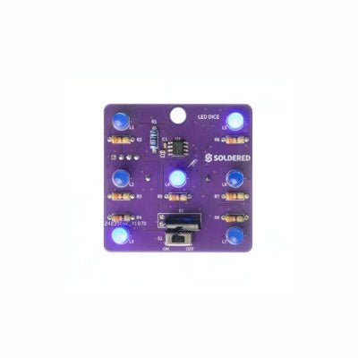
If you are looking for an easy way to get started with soldering or simply want to make a small portable gadget, this set is a great opportunity. "LED cube" is an educational set for learning the soldering skill, with which you get a small electronic game at the end. After you turn on and shake this board, certain leds will light up randomly and symbolize the number, as if a real die had been thrown.
It is based on the Attiny404 microcontroller, programmed in Arduino, and there is a battery on the back which makes this gadget portable. There is also a keychain so you can always carry your new game with you! Soldering is easy according to the markings on the board.
Included
1x PCB
1x ATtiny404 microcontroller
7x LEDs
7x Resistors (330 ohm)
1x Resistor (10 kohm)
1x Battery holder
1x CR2032 battery
1x Switch
1x Vibration sensor SW-18020P
1x Keychain ring
The FRDM-MCXN947 is a compact and versatile development board designed for rapid prototyping with MCX N94 and N54 microcontrollers. It features industry-standard headers for easy access to the MCU's I/Os, integrated open-standard serial interfaces, external flash memory, and an onboard MCU-Link debugger.
Specificaties
Microcontroller
MCX-N947 Dual Arm Cortex-M33 cores @ 150 MHz each with optimized performance efficiency, up to 2 MB dual-bank flash with optional full ECC RAM, External flash
Accelerators: Neural Processing Unit, PowerQuad, Smart DMA, etc.
Memory Expansion
*DNP Micro SD card socket
Connectivity
Ethernet Phy and connector
HS USB-C connectors
SPI/I²C/UART connector (PMOD/mikroBUS, DNP)
WiFi connector (PMOD/mikroBUS, DNP)
CAN-FD transceiver
Debug
On-board MCU-Link debugger with CMSIS-DAP
JTAG/SWD connector
Sensor
P3T1755 I³C/I²C Temp Sensor, Touch Pad
Expansion Options
Arduino Header (with FRDM expansion rows)
FRDM Header
FlexIO/LCD Header
SmartDMA/Camera Header
Pmod *DNP
mikroBUS
User Interface
RGB user LED, plus Reset, ISP, Wakeup buttons
Inbegrepen
1x FRDM-MCXN947 Development Board
1x USB-C Cable
1x Quick Start Guide
Downloads
Datasheet
Block diagram
The Challenger RP2040 WiFi is a small embedded computer equipped with a WiFi module, in the popular Adafruit Feather form factor. It is based on an RP2040 microcontroller chip from the Raspberry Pi Foundation which is a dual-core Cortex-M0 that can run on a clock up to 133 MHz. The RP2040 is paired with a 8 MB high-speed flash capable of supplying data up to the max speed. The flash memory can be used both to store instructions for the microcontroller as well as data in a file system and having a file system available makes it easy to store data in a structured and easy to program approach. The device can be powered from a Lithium Polymer battery connected through a standard 2.0 mm connector on the side of the board. An internal battery charging circuit allows you to charge your battery safely and quickly. The device is shipped with a programming resistor that sets the charging current to 250 mA. This resistor can be exchanged by the user to either increase or decrease the charging current, depending on the battery that is being used. The WiFi section on this board is based on the Espressif ESP8285 chip which basically is a ESP8266 with 1 MB flash memory integrated onto the chip making it a complete WiFi only requiring very few external components. The ESP8285 is connected to the microcontroller using a UART channel and the operation is controlled using a set of standardized AT-commands. Specifications Microcontroller RP2040 from Raspberry Pi (133 MHz dual-core Cortex-M0) SPI One SPI channel configured I²C One I²C channel configured UART One UART channel configured (second UART is for the WiFi chip) Analog inputs 4 analog input channels WLAN controller ESP8285 from Espressif (160 MHz single-core Tensilica L106) Flash memory 8 MByte, 133 MHz SRAM memory 264 KByte (divided into 6 banks) USB 2.0 controller Up to 12 MBit/s full speed (integrated USB 1.1 PHY) JST Battery connector 2.0 mm pitch Onboard LiPo charger 250 mA standard charge current Onboard NeoPixel LED RGB LED Dimensions 51 x 23 x 3,2 mm Weight 9 g Downloads Datasheet Design files Product errata
Bluno is de eerste in zijn soort die Bluetooth 4.0 (BLE) module integreert in Arduino Uno, waardoor het een ideaal prototyping platform is voor zowel software- als hardware-ontwikkelaars om BLE te gaan gebruiken. Je zult in staat zijn om je eigen slimme armband, slimme stappenteller, en nog veel meer te ontwikkelen. Door de low-power Bluetooth 4.0 technologie, kan real-time low energy communicatie heel eenvoudig worden gemaakt.Bluno integreert een TI CC2540 BT 4.0 chip met de Arduino UNno. Het maakt draadloos programmeren via BLE mogelijk, ondersteunt Bluetooth HID, AT commando om BLE te configureren en je kunt BLE firmware eenvoudig upgraden. Bluno is ook compatibel met alle 'Arduino Uno' pinnen wat betekent dat elk project gemaakt met Uno direct draadloos kan gaan! Specificaties
On-board BLE chip: TI CC2540
Draadloze programmering via BLE
Ondersteunt Bluetooth HID
Support AT commando om de BLE
te configurerenTransparante communicatie via seriële
Gemakkelijke upgrade van BLE-firmware
DC-voeding: USB-voeding of externe 7~12 V DC
Microcontroller: Atmega328
Bootloader: Arduino Uno (ontkoppel elk BLE-apparaat voordat u een nieuwe schets uploadt)
Compatibel met de Arduino Uno pin mapping
Afmeting: 60 x 53 mm (2.36 x 2.08')
Gewicht: 30 g
GrovePi+ is stacked on top of the Raspberry Pi without the need for any other connections. Communication between the two occurs over the I2C interface. All Grove modules connect to the universal Grove connectors on the GrovePi+ shield via the universal 4 pin connector cable.
Grove modules work on analog and digital signals and can be connected directly to the ATMEGA328 microcontroller on the Grove Pi+. The microcontroller acts as an interpreter between the Raspberry Pi and the Grove sensors. It sends, receives, and executes commands sent by the Raspberry Pi.
Features
One GrovePi+ board together with 12 popular Grove sensors and 10 Grove cables
GrovePi+ is compatible with Raspberry Pi A+, B, B+ / 2, 3, 4.
CE certified and compatible with Linux and Win 10 IoT.
Included
1x Grove Pi+
1x Grove - Rotary Angle Sensor
1x Grove - Sound Sensor
1x Grove - LCD RGB Backlight
1x Grove - Temp&Humi Sensor
1x Grove - Red LED
1x Grove - Light Sensor
1x Grove - Buzzer
1x Grove - Relay
1x Grove - Blue LED
1x Grove - Button
1x GrovePi+ Guidebook
10x Cables
1x Grove - UItrasonic Ranger
1x Grove - Green LED
Grove Piezo Vibration Sensor is suitable for measurements of flexibility, vibration, impact and touch. The module is based on PZT film sensor LDT0-028. When the sensor moves back and forth, a certain voltage will be created by the voltage comparator inside of it.Therefore, outputs high & low levels. In spite of the fact that it has a high receptivity for strong impacts, a wide dynamic range (0.001 Hz~1000 MHz) also guarantees excellent measuring performance. Finally, you can adjust its sensitivity by adjusting the potentiometer with a screw.Features
Standard grove socket
Wide dynamic range?0.001 Hz~1000 MHz
Adjustable sensitivity
High receptivity for strong impact
Applications
Vibration Sensing in Washing Machine
Low Power Wake-up Switch
Low-Cost Vibration Sensing
Car Alarms
Body Movement
Security Systems
Downloads
Download Wiki PDF
Grove - Piezo Vibration Sensor Eagle File
Grove - Piezo Vibration Sensor Schematic PDF File
Grove - Piezo Vibration Sensor PCB PDF File
Piezo Vibration Sensor Datasheet
De MicroMod DIY Carrier Kit bevat vijf M.2 connectoren (4.2mm hoogte), schroeven en standoffs zodat u over alle speciale onderdelen beschikt die u nodig heeft om uw eigen carrier-board te maken. MicroMod gebruikt de standaard M.2 connector. Dit is dezelfde connector als die op moderne moederborden en laptops. Er zijn verschillende plaatsen voor de plastic 'key' op de M.2 connector om te voorkomen dat een gebruiker er een niet-compatibel apparaat insteekt. De MicroMod standaard gebruikt de 'E'-key en wijkt van de M.2 standaard af doordat de montageschroef 4 mm naar de zijkant is verplaats. De 'E'-key is vrij gangbaar, zodat een gebruiker een M.2-compatibele Wifi-module zou kunnen plaatsen. Maar omdat de schroefbevestiging niet uitgelijnd is, zou de gebruiker een niet-compatibel apparaat niet kunnen vastzetten op een MicroMod-carrier. Eigenschappen 5x kruiskopschroef M2.5 x 3 mm 5x SMD Reflow Compatible Standoffs M2.5 x 2,5mm 5x M.2 MicroMod Connector Key: E Hoogte: 4.2 mm Aantal pennen: 67 Pitch: 0.5 mm
The SparkFun RP2040 mikroBUS Development Board is a low-cost, high performance platform with flexible digital interfaces featuring the Raspberry Pi Foundation's RP2040 microcontroller. Besides the Thing Plus or Feather PTH pin layout, the board also includes a microSD card slot, 16 MB (128 Mbit) flash memory, a JST single cell battery connector (with a charging circuit and fuel gauge sensor), an addressable WS2812 RGB LED, JTAG PTH pins, four (4-40 screw) mounting holes, our signature Qwiic connectors, and a mikroBUS socket. The mikroBUS standard was developed by MikroElektronika. Similar to Qwiic and MicroMod interfaces, the mikroBUS socket provides a standardized connection for add-on Click boards to be attached to a development board and is comprised of a pair of 8-pin female headers with a standardized pin configuration. The pins consist of three groups of communications pins (SPI, UART and I²C), six additional pins (PWM, Interrupt, Analog input, Reset and Chip select), and two power groups (3.3 V and 5 V). The RP2040 is supported with both C/C++ and MicroPython cross-platform development environments, including easy access to runtime debugging. It has UF2 boot and floating-point routines baked into the chip. While the chip has a large amount of internal RAM, the board includes an additional 16 MB of external QSPI flash memory to store program code. The RP2040 contains two ARM Cortex-M0+ processors (up to 133 MHz) and features: 264 kB of embedded SRAM in six banks 6 dedicated IO for SPI Flash (supporting XIP) 30 multifunction GPIO: Dedicated hardware for commonly used peripherals Programmable IO for extended peripheral support Four 12-bit ADC channels with internal temperature sensor (up to 0.5 MSa/s) USB 1.1 Host/Device functionality Features (SparkFun RP2040 mikroBUS Dev. Board) Raspberry Pi Foundation's RP2040 microcontroller 18 Multifunctional GPIO Pins Four available 12-bit ADC channels with internal temperature sensor (500kSa/s) Up to eight 2-channel PWM Up to two UARTs Up to two I²C buses Up to two SPI buses Thing Plus (or Feather) Pin Layout: 28 PTH Pins USB-C Connector: USB 1.1 Host/Device functionality 2-pin JST Connector for a LiPo Battery (not included): 500mA charging circuit 4-pin JST Qwiic Connector LEDs:
PWR - Red 3.3V power indicator
CHG - Yellow battery charging indicator
25 - Blue status/test LED (GPIO 25)
WS2812 - Addressable RGB LED (GPIO 08) Buttons: Boot Reset JTAG PTH Pins 16MB QSPI Flash Memory µSD Card Slot mikroBUS Socket Dimensions: 3.7' x 1.2' Four Mounting Holes: 4-40 screw compatible Downloads Schematic Eagle Files Board Dimensions Hookup Guide Qwiic Info Page GitHub Hardware Repository
Deze set bevat 3 mondstukken voor hetelucht-reworkstations zoals ZD-8922 of ZD-8968.
Inbegrepen
1x Heteluchtmondstuk 79-3911
1x Heteluchtmondstuk 79-3912
1x Heteluchtmondstuk 79-3913
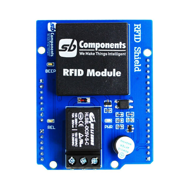
Designed with convenience and security in mind, the Ardi RFID Shield is based on the EM-18 module, operating at a frequency of 125 KHz. This shield allows you to easily integrate RFID (Radio Frequency Identification) technology into your projects, enabling seamless identification and access control systems.
Equipped with a powerful 1-channel optoisolated relay, the Ardi RFID Shield offers a reliable switching solution with a maximum DC rating of 30 V and 10 A, as well as an AC rating of 250 V and 7 A. Whether you need to control lights, motors, or other high-power devices, this shield provides the necessary functionality.
Additionally, the Ardi RFID Shield features an onboard buzzer that can be utilized for audio feedback, allowing for enhanced user interaction and system feedback. With the onboard 2-indication LEDs, you can easily monitor the status of RFID card detection, power supply, and relay activation, providing clear visual cues for your project's operation.
Compatibility is key, and the Ardi RFID Shield ensures seamless integration with the Arduino Uno platform. Paired with a read-only RFID module, this shield opens up a world of possibilities for applications such as access control systems, attendance tracking, inventory management, and more.
Features
Onboard 125 kHz EM18 RFID small, compact module
Onboard High-quality relays Relay with Screw terminal and NO/NC interfaces
Shield compatible with both 3.3 V and 5 V MCU
Onboard 3 LEDs power, relay ON/OFF State and RFID Scan status
Multi-tone Buzzer onboard for Audio alerts
Mounts directly onto ArdiPi, Ardi32 or other Arduino compatible boards
Specifications
RFID operating Frequency: 125 kHz
Reading distance: 10 cm, depending on TAG
Integrated Antenna
Relay Max Switching Voltage: 250 V AC/30 V DC
Relay Max Switching Current: 7 A/10 A
The CubeCell series is designed primarily for LoRa/LoRaWAN node applications.
Built on the ASR605x platform (ASR6501, ASR6502), these chips integrate the PSoC 4000 series MCU (ARM Cortex-M0+ Core) with the SX1262 module. The CubeCell series offers seamless Arduino compatibility, stable LoRaWAN protocol operation, and straightforward connectivity with lithium batteries and solar panels.
The HTCC-AB02S is a developer-friendly board with an integrated AIR530Z GPS module, ideal for quickly testing and validating communication solutions.
Features
Arduino compatible
Based on ASR605x (ASR6501, ASR6502), those chips are already integrated the PSoC 4000 series MCU (ARM Cortex M0+ Core) and SX1262
LoRaWAN 1.0.2 support
Ultra low power design, 21 uA in deep sleep
Onboard SH1.25-2 battery interface, integrated lithium battery management system (charge and discharge management, overcharge protection, battery power detection, USB/battery power automatic switching)
Good impendence matching and long communication distance
Onboard solar energy management system, can directly connect with a 5.5~7 V solar panel
Micro USB interface with complete ESD protection, short circuit protection, RF shielding, and other protection measures
Integrated CP2102 USB to serial port chip, convenient for program downloading, debugging information printing
Onboard 0.96-inch 128x64 dot matrix OLED display, which can be used to display debugging information, battery power, and other information
Using Air530 GPS module with GPS/Beidou Dual-mode position system support
Specifications
Main Chip
ASR6502 (48 MHz ARM Cortex-M0+ MCU)
LoRa Chipset
SX1262
Frequency
863~870 MHz
Max. TX Power
22 ±1 dBm
Max. Receiving Sensitivity
−135 dBm
Hardware Resource
2x UART1x SPI2x I²C1x SWD3x 12-bit ADC input8-channel DMA engine16x GPIO
Memory
128 Kb FLASH16 Kb SRAM
Power consumption
Deep sleep 21 uA
Interfaces
1x Micro USB1x LoRa Antenna (IPEX)2x (15x 2.54 Pin header) + 3x (2x 2.54 Pin header)
Battery
3.7 V lithium battery (power supply and charging)
Solar Energy
VS pin can be connected to 5.5~7 V solar panel
USB to Serial Chip
CP2102
Display
0.96" OLED (128 x 64)
Operating temperature
−20~70°C
Dimensions
55.9 x 27.9 x 9.5 mm
Included
1x CubeCell HTCC-AB02S Development Board
1x Antenna
1x 2x SH1.25 battery connector
Downloads
Datasheet
Schematic
GPS module (Manual)
Quick start
GitHub
De Portenta C33 is een krachtige System-on-Module, ontworpen voor goedkope Internet of Things (IoT) toepassingen. Hij is gebaseerd op de R7FA6M5BH2CBG microcontroller van Renesas, heeft dezelfde afmetingen als de Portenta H7, en is ook backward compatible daarmee. Hierdoor is hij volledig compatibel met alle shields en carriers uit de Portenta familie, met gebruik daarbij van zijn high-density aansluitingen. Met zijn lage kosten is de Portenta C33 is een uitstekende keuze voor ontwikkelaars die met een beperkt budget IoT apparaten en toepassingen willen maken. Of u nu een smarthome apparaat of een online industriële sensor bouwt, de Portenta C33 biedt de rekenkracht en connectiviteitsopties die nodig zijn om de klus te klaren. Het snel implementeren van AI-gestuurde projecten kan vlot en eenvoudig met de Portenta C33. Er kan gebruik worden gemaakt van een breed scala aan kant-en-klaar beschikbare software libraries en Arduino sketches, evenals widgets, die gegevens realtime weergeven op Arduino IoT Cloud gebaseerde dashboards. Kenmerken Ideaal voor goedkope IoT-toepassingen met wifi / Bluetooth LE connectiviteit Ondersteunt MicroPython en andere hoogwaardige programmeertalen Biedt beveiliging van industriële kwaliteit op hardware niveau, en veilige OTA firmware-updates Maakt gebruik van kant-en-klare software libraries en Arduino sketches Perfect geschikt om realtime gegevens te bewaken en weer te geven op Arduino IoT Cloud widget-gebaseerde dashboards Compatibel met de Arduino Portenta en MKR familie Voorzien van castellaties voor automatische assemblagelijnen Kosteneffectief presteren Met een betrouwbaarheid, veiligheid en rekenkracht die in zijn klasse niet misstaat is de Portenta C33 geschikt om veel grote en kleine bedrijven de mogelijkheid te bieden aan de slag te gaan met IoT, en zo te profiteren van een hoger niveau van efficiëntie en automatisering. Toepassingen De Portenta C33 brengt meer toepassingen dan ooit binnen het bereik van gebruikers. Van het mogelijk maken van snelle plug-and-play prototyping tot het bieden van een kosteneffectieve oplossing voor projecten op industriële schaal. Industriële IoT-gateway Machine monitoring om OEE/OPE te kunnen volgen Inline kwaliteitscontrole en -borging Monitoring van energieverbruik Aansturing van apparaten Kant-en-klare oplossing voor IoT-prototyping Specificaties Microcontroller Renesas R7FA6M5BH2CBG ARM Cortex-M33: ARM Cortex-M33 core tot 200 MHz 512 kB SRAM ingebouwd 2 MB ingebouwde Flash Arm TrustZone Secure Crypto Engine 9 Extern geheugen 16 MB QSPI Flash USB-C USB-C High Speed Connectiviteit 100 MB Ethernet interface (PHY) Wifi Bluetooth Low Energy Interfaces CAN SD-kaart ADC GPIO SPI I²S I²C JTAG/SWD Security NXP SE050C2 Secure Element Bedrijfstemperatuur -40 tot +85 °C (-40 tot 185 °F) Afmetingen 66,04 x 25,40 mm Downloads Datasheet Schema