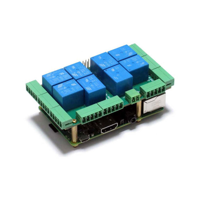
The Home Automation HAT uses only pluggable connectors. In addition, the latest release (V4.0 and up) has two new communication ports: 1-Wire and RS485.The card uses only 5 V power. On-board step-up power supply generates 12 V to power the 0-10 V analog outputs.A general purpose push-button, wired directly to a Raspberry Pi GPIO pin, can be used to shut down Raspberry Pi without a keyboard, or to force any output to a desired state.
Ideal solution for your Raspberry Pi Home Automation projects.
Read temperatures in up to 8 zones with analog inputs.
Control your heating and cooling system with the 8 onboard relays.
Use the 8 optically isolated digital inputs for your security system.
Activate the hardware watchdog to monitor and power cycle the Raspberry Pi in case of software lockup.
Control four-light systems with the four PWM open-drain outputs (you supply external power up to 24 V).
Control four light dimmers using 0-10 V outputs.
CompatibilityThe card is compatible with all Raspberry Pi versions from Zero to 4. It shares the I²C bus using only two of the Raspberry Pi’s GPIO pins to manage all eight cards. This feature leaves the remaining 24 GPIOs available for the user.Power RequirementsThe Home Automation card needs 5 V to operate and can be powered from Raspberry Pi or from its own pluggable connector. The onboard relay coils are also powered from the 5 V. An on-board 5V to 12V step-up power supply generates the voltage to drive the 0-10 V analog outputs. A local 3.3 V regulator powers the rest of the circuitry. The card needs 50 mA to operate with all relays off. Each relay needs up to 80 mA to turn on. RelaysThe 8 on-board relays have contacts brought out to heavy duty pluggable connectors, which make the card easy to use when multiple cards are stacked up. Relays are grouped in two sections of four relays each, with one common terminal and one N-O contact for each relay. Relays are rated 10 A/24 VDC and 250 VAC, but due to the board geometry limitation, the relays can switch only 3 A and 24 V, AC or DC. Status LEDs show when RELAYS are ON or OFF.Stacking Multiple CardsUp to eight Home Automation cards can be stacked on your Raspberry Pi. Each card is identified by jumpers you install to indicate the level in the stack. Cards can be installed in any order. The three position jumper on the upper right corner of the card selects the stack level.Features
Eight relays with status LEDs and and N.O contacts
Eight layer stackable
Eight 12-bit A/D inputs, 250 Hz sample rate
Four 13-bit DAC outputs (0-10 V dimmers)
Four PWM 24 V/4 A open-drain outputs
Eight optically isolated digital inputs
Contact closure/Event counters up to 500 Hz
Four Quadrature Encoder inputs
26 GPIOs from Raspberry Pi available
1-WIRE and RS485 communication ports
Pluggable Connectors 26-16 AWG for all ports
On-board hardware watchdog
On-board resettable fuse
Reverse power supply protection
Brass stand-offs, screws and nuts included
Hardware self-test with loop-back cable
Open source hardware, schematics available
32-bit Processor running at 64 MHz
Uses only I²C port (address 0x28..0x2f ), all GPIO pins available
Specifications
Power supply: Pluggable Connector, 5 V/3 A
Power consumption: 50 mA (all relays off), 700 mA (all relays on)
On board resettable fuse: 3 A
Open Drain outputs: maximum 3 A, 24 V
Relays 1,2,3,4,5,8: N-O contacts, 6 A/24 VAC or DC
Relays 6,7: 3 A/24 VAC or DC
Analog Inputs:
Maximum input voltage: 3 V
Input Impedance: 50 K?
Resolution: 12 bits
Sample rate: 250 samples/sec.
DAC Outputs:
Resistive load: Minimum 1 K?
Accuracy: ±1%
Opto-isolated Digital Inputs:
Input Forward Current: Typical 5 mA, maximum 50 mA
Input Series Resistor: 1K
Input Reverse Voltage: 5 V
Input Forward Voltage: 25 V @ 10 mA
Isolation Resistance: Minimum 1012 ?
Included
Home Automation stackable Card for Raspberry Pi with self-test Card
Mounting hardware
4x M2.5x18 mm male-female brass standoffs
4x M2.5x5 mm brass screws
4x M2.5 brass nuts
2x Stack level Jumpers
All required Connector Plugs
Laminated Plastic Card showing IO Pinout
Downloads
User's Guide
Open Source Hardware Schematic
2D CAD Drawing
Command Line
Python Libraries
Node-RED Nodes
Domoticz Plugin
OpenPLC
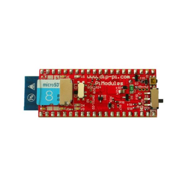
The DiP-Pi PIoT is an Advanced Powered, WiFi connectivity System with sensors embedded interfaces that cover most of possible needs for IoT application based on Raspberry Pi Pico. It can supply the system with up to 1.5 A @ 4.8 V delivered from 6-18 VDC on various powering schemes like Cars, Industrial plant etc., additionally to original micro-USB of the Raspberry Pi Pico. It supports LiPo or Li-Ion Battery with Automatic Charger as also automatic switching from cable powering to battery powering or reverse (UPS functionality) when cable powering lost. Extended Powering Source (EPR) is protected with PPTC Resettable fuse, Reverse Polarity, as also ESD.The DiP-Pi PIoT contains Raspberry Pi Pico embedded RESET button as also ON/OFF Slide Switch that is acting on all powering sources (USB, EPR or Battery). User can monitor (via Raspberry Pi Pico A/D pins) battery level and EPR Level with PICO’s A/D converters. Both A/D inputs are bridged with 0402 resistors (0 OHM) therefore if for any reason user needs to use those Pico pins for their own application can be easy removed. The charger is automatically charging connected battery (if used) but in addition user can switch charger ON/OFF if their application needs it.DiP-Pi PIoT can be used for cable powered IoT systems, but also for pure Battery Powered System with ON/OFF. Each powering source status is indicated by separate informative LEDs (VBUS, VSYS, VEPR, CHGR, V3V3).User can use any capacity of LiPo or Li-Ion type; however, must take care to use PCB protected batteries with max discharge current allowed of 2 A. The embedded battery charger is set to charge battery with 240 mA current. This current is set by resistor so if user need more/less can himself to change it. The DiP-Pi PIoT is also equipped with WiFi ESP8266 Clone module with embedded antenna. This feature open a wide range of IoT applications based on it.In Addition to all above features DiP-Pi PIoT is equipped with embedded 1-wire, DHT11/22 sensors, and micro–SD Card interfaces. Combination of the extended powering, battery, and sensors interfaces make the DiP-Pi PIoT ideal for IoT applications like data logger, plants monitoring, refrigerators monitoring etc.DiP-Pi PIoT is supported with plenty of ready to use examples written in Micro Python or C/C++.SpecificationsGeneral
Dimensions 21 x 51 mm
Raspberry Pi Pico pinout compatible
Independent Informative LEDs (VBUS, VSYS, VEPR, CHGR, V3V3)
Raspberry Pi Pico RESET Button
ON/OFF Slide Switch acting on all powering sources (USB, EPR, Battery)
External Powering 6-18 VDC (Cars, Industrial Applications etc.)
External Power (6-18 VDC) Level Monitoring
Battery Level Monitoring
Inverse Polarity Protection
PPTC Fuse Protection
ESD Protection
Automatic Battery Charger (for PCB protected LiPo, Li-Ion – 2 A Max) Automatic/User Control
Automatic Switch from Cable Powering to Battery Powering and reverse (UPS Functionality)
Various powering schemes can be used at the same time with USB Powering, External Powering and Battery Powering
1.5 A @ 4.8 V Buck Converter on EPR
Embedded 3.3 V @ 600 mA LDO
ESP8266 Clone WiFi Connectivity
ESP8266 Firmware Upload Switch
Embedded 1-wire Interface
Embedded DHT-11/22 Interface
Powering Options
Raspberry Pi Pico micro-USB (via VBUS)
External Powering 6-18 V (via dedicated Socket – 3.4/1.3 mm)
External Battery
Supported Battery Types
LiPo with protection PCB max current 2A
Li-Ion with protection PCB max current 2A
Embedded Peripherals and Interfaces
Embedded 1-wire interface
Embedded DHT-11/22 Interface
Micro SD Card Socket
Programmer Interface
Standard Raspberry Pi Pico C/C++
Standard Raspberry Pi Pico Micro Python
Case CompatibilityDiP-Pi Plexi-Cut CaseSystem Monitoring
Battery Level via Raspberry Pi Pico ADC0 (GP26)
EPR Level via Raspberry Pi Pico ADC1 (GP27)
Informative LEDs
VB (VUSB)
VS (VSYS)
VE (VEPR)
CH (VCHR)
V3 (V3V3)
System Protection
Direct Raspberry Pi Pico Hardware Reset Button
ESD Protection on EPR
Reverse Polarity Protection on EPR
PPTC 500 mA @ 18 V fuse on EPR
EPR/LDO Over Temperature protection
EPR/LDO Over Current protection
System Design
Designed and Simulated with PDA Analyzer with one of the most advanced CAD/CAM Tools – Altium Designer
Industrial Originated
PCB Construction
2 ozcopper PCB manufactured for proper high current supply and cooling
6 mils track/6 mils gap technology 2 layers PCB
PCB Surface Finishing – Immersion Gold
Multi-layer Copper Thermal Pipes for increased System Thermal Response and better passive cooling
Downloads
Datasheet
Manual
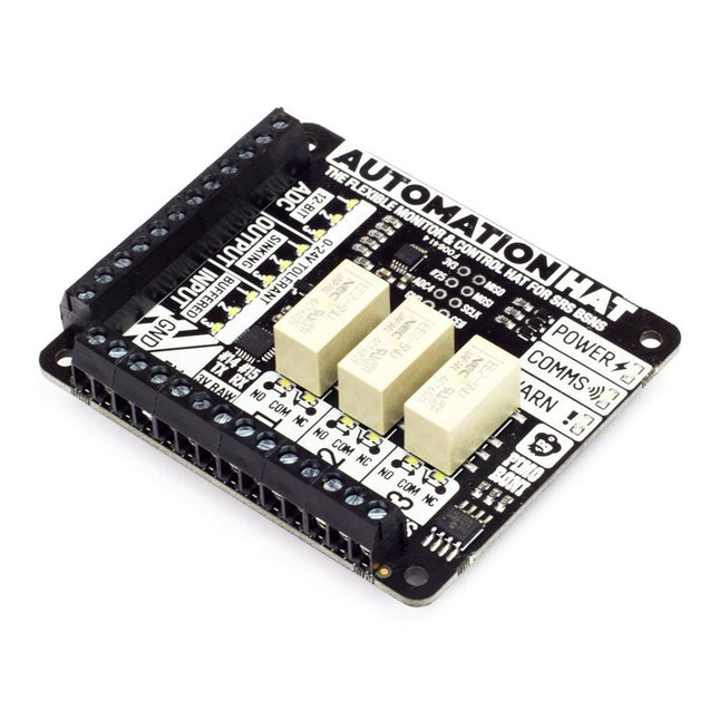
Take control of and monitor your world with our ultimate jack-of-all-trades Raspberry Pi HAT!We've pulled together a great set of features into this home monitoring and automation controller. With relays, analog channels, powered outputs, and buffered inputs (all 24 V tolerant) you can now hook up a plethora of goodies to your Raspberry Pi all at once.Better still each channel has an indicator LEDs which means at a glance you can see what's happening with your setup. Even the analog channels have dimming LEDs that allow you to see the value they are currently sensing – swish!Ideal for smart home and automation projects, giving your greenhouse intelligent sprinklers, or scheduling your fish feeding!Features
3x 24 V @ 2 A relays (NC and NO terminals)
3x 12-bit ADC @ 0-24 V (±2% accuracy)
3x 24 V tolerant buffered inputs
3x 24 V tolerant sinking outputs
15x channel indicator LEDs
1x 12-bit ADC @ 0-3.3 V
3.5 mm screw terminals
Power, Comms, and Warn! LED indicators
SPI, TX (#14), RX (#15), #25 pins broken out
Automation HAT pinout
Compatible with all 40-pin header Raspberry Pi models
Python library
Schematic
Comes fully assembled (broken out pins require soldering)
SoftwareAs ever, we've made a super-simple to use Python library to take advantage of Automation HAT's multitudinous functions, with examples to get you started.Our input, output and relay examples show you how to read the analog and digital inputs, switch the outputs on and off, and control the relays.Notes
We recommend you use a set of brass M2.5 standoffs with Automation HAT to avoid pins contacting the HDMI port if the HAT is pushed down
Loads for the buffered outputs should be switched on the ground side, i.e. 12/24 V (from supply) -> load -> output terminal -> ground (from supply)
The relays can tolerate up to 2 A each and should be switched on the high side
The sinking outputs can sink a maximum 500 mA total across the 3 outputs, so if you use a single channel you can sink the whole 500 mA across it.
The accuracy of the ADC is ±2%.
Do not use to switch mains voltages!
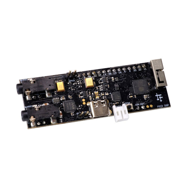
PÚCA DSP is an open-source, Arduino-compatible ESP32 development board for audio and digital signal processing (DSP) applications with expansive audio-processing features. It provides audio inputs, audio outputs, a low-noise microphone array, an integrated test-speaker option, additional memory, battery-charge management, and ESD protection all on a small, breadboard-friendly PCB.
Synthesizers, Installations, Voice UI, and More
PÚCA DSP can be used for a wide range of DSP applications, including but not limited to those in the fields of music, art, creative technology, and adaptive technology. Music-related examples include digital-music synthesis, mobile recording, Bluetooth speakers, wireless line-level directional microphones, and the design of smart musical instruments. Art-related examples include acoustic sensor networks, sound-art installations, and Internet-radio applications. Examples related to creative and adaptive technology include voice user interface (VUI) design and Web audio for the Internet of Sounds.
Compact, Integrated Design
PÚCA DSP was designed for portability. When used with an external 3.7 V rechargeable battery, it can be deployed almost anywhere or integrated into just about any device, instrument, or installation. Its design emerged from months of experimentation with various ESP32 development boards, DAC breakout boards, ADC breakout boards, Microphone breakout boards, and audio-connector breakout boards, and – despite its diminutive size – it manages to provide all of that functionality in a single board. And it dos so without compromising signal quality.
Specifications
Processor & Memory
Espressif ESP32 Pico D4 Processor
32-bit dual core 80 MHz / 160 MHz / 240 MHz
4 MB SPI Flash with 8 MB additional PSRAM (Original Edition)
Wireless 2.4 GHz Wi-Fi 802.11b/g/n
Bluetooth BLE 4.2
3D Antenna
Audio
Wolfson WM8978 Stereo Audio Codec
Audio Line In on 3.5 mm stereo onnector
Audio Headphone / Line Out on 3.5 mm stereo connector
Stereo Aux Line In, Audio Mono Out routed to GPIO Header
2x Knowles SPM0687LR5H-1 MEMS Microphones
ESD protection on all audio inputs and outputs
Support for 8, 11.025, 12, 16, 22.05, 24, 32, 44.1 and 48 kHz sample rates
1 W Speaker Driver, routed to GPIO Header
DAC SNR 98 dB, THD -84 dB (‘A’ weighted @ 48 kHz)
ADC SNR 95 dB, THD -84 dB (‘A’ weighted @ 48 kHz)
Line input impedance: 1 MOhm
Line output impedance: 33 Ohm
Form Factor and Connectivity
Breadboard friendly
70 x 24 mm
11x GPIO pins broken out to 2.54 mm pitch header, with access to both ESP32 ADC channels, JTAG and capacitive touch pins
USB 2.0 over USB Type C connector
Power
3.7/4.2 V Lithium Polymer Rechargeable Battery, USB or external 5 V DC power source
ESP32 and Audio Codec can be placed into low power modes under software control
Battery voltage level detection
ESD protection on USB data bus
Downloads
GitHub
Datasheet
Links
Crowd Supply Campaign (includes FAQs)
Hardware Overview
Programming the Board
The Audio Codec
This QWIIC connector allows you to easily connect QWIIC enabled modules to a Raspberry Pi, without the need for soldering. It uses a 2x3 pin female header which sits on top of the first 6 GPIO pins and breaks out the 3.3v, GND and the two I²C pins (SDA, SCL) on a 4 pin JST connector which sits on top.
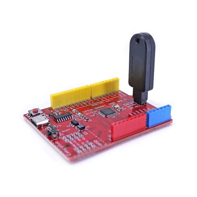
Deze programmeur is speciaal ontworpen voor het branden van bootloaders (zonder computer) op Arduino-compatibele ATmega328P/ATmega328PB-ontwikkelborden.
Sluit de programmeur eenvoudigweg aan op de ICSP-interface om de bootloader opnieuw te branden. Het is ook compatibel met nieuwe chips, op voorwaarde dat de IC functioneel is.
Opmerking: Als u een bootloader brandt, worden alle eerdere chipgegevens gewist.
Kenmerken
Werkspanning: 3,1-5,3 V
Werkstroom: 10 mA
Compatibel met op Arduino Uno R3 gebaseerde borden (ATmega328P of ATmega328PB)
Afmetingen: 39,6 x 15,5 x 7,8 mm
Elektor GREEN en GOLD leden kunnen deze uitgave hier downloaden.
Nog geen lid? Klik hier om een lidmaatschap af te sluiten.
STM32 Wireless Innovation Design Contest: de winnaars
In-circuit LC-meteroverwegingen bij een prototype
AmpVolt: een modulaire DC-vermogensmeter (deel 1)meet gelijkstroom en energieverbruik tot 50 V en 5 A
embedded world 2024
Elektronische apparatuur reparerentools, technieken en tips
Alle begin... - NL TRANSLATION...gaat verder met de opamp-theorie
Eenvoudige DDS-signaalgeneratordirecte digitale synthese in zijn puurste vorm
Sparkplug bekekenspecificatie voor MQTT-data
De CRTCvreemde onderdelen
Radargestuurde verlichtingautomatische trapverlichting met personendetectie
Digitale waterpas en actieve stroboscoop voor draaitafelsregel je platenspeler perfect af met dit alles-in-één tool
Onderzoek naar de uitdagingen en commerciële waarde van open source-elektronica (2)
Ronde M12-connector met A-coderingvoorkeursoplossing voor industriële toepassingen
Het Arduino-Inside Measurement Labeen 8-in-1 test- en meetinstrument voor de elektronica-werkbank
Frequentie-, fase- en impedantieanalyse met een geluidskaartvoor frequenties van 100 Hz tot 90 kHz
Zuurgraad meten met de Arduino UNO R4controleer de waterkwaliteit
Uit het leven gegrepenpangpongbilletjes-lanceermachine
FNIRSI 1014D digitale geheugenoscilloscoopgoede prestaties voor weinig geld
2024: een AI-odysseeobjectdetectie aan de praat krijgen
10MHz-referentiegeneratorzeer nauwkeurig, met verdeler en galvanische isolatie
Project-update #2: ESP32-gebaseerde energiemeterenkele verbeteringen
Project 2.0correcties, updates en brieven van lezers
Een vraaggesprek met Eben Upton, CEO van Raspberry Pide Raspberry Pi 5 – en daarna
Tegenwoordig gebruiken steeds meer en slimmere telefoons en laptops USB-C poorten vanwege de krachtige mogelijkheid om stroom-, gegevens- en video-informatie tegelijk te verzenden. Een USB-C aansluiting kan het apparaat ook veel dunner maken, in vergelijking met bijvoorbeeld Thunderbolt 3 of de HDMI-compatibele poorten. Daarom hebben we de CrowVi draagbare USB-C monitor ontwikkeld.Het superdunne CrowVi 13,3' scherm heeft 2 USB-C poorten, de ene is voor de stroomvoorziening en de andere is voor gegevensoverdracht van video en touchscreen opdrachten. Het scherm kan ook worden aangesloten via de mini HDMI-compatibele poort. De resolutie van de CrowVi is 1920x1080, wat een betere ervaring biedt bij het gamen en bij het bekijken van films.Kenmerken
De behuizing van de CrowVi is gemaakt van een aluminiumlegering, de dikte is slechts 5 mm en ook de schermrand bedraagt maar 6 mm. Het hele scherm ziet er prachtig en elegant uit.
De CrowVi fungeert niet slechts als extra display voor smartphones en laptops, maar kan ook als basisscherm worden ingezet bij gaming apparaten en sommige computers, zoals de Mac mini, de Raspberry Pi, enz.
In vergelijking met een telefoon biedt de CrowVi een veel groter scherm. Hij zorgt daarmee voor een betere ervaring bij gaming en bij het bekijken van films.
Specificaties
Scherm
13,3' TFT IPS LCD
Schermgrootte
294,5 x 164 mm
Dikte
5 - 10 mm
Resolutie
1920 x 1080
Helderheid
300 nits
Vernieuwingsfrequentie
60 Hz
Kleurengamma
16,7 M, NTSC 72%, sRGB tot 100%
Contrast
800:1
Achtergrondverlichting
LED
Kijkhoek
178°
Aspect ratio
16:9
Speaker
Dubbele luidsprekers 8 ?, 2 W
Behuizing
Aluminiumlegering
Input
Mini-HD, Type-C, PD
Uitgang
3,5 mm koptelefoonaansluiting
Voeding
PD 5 - 20 V, of USB-C 3.0
Werktemperatuur
0 - 50° C
Afmetingen
313 x 198 x 10 mm
Gewicht (smart case)
350 g
Gewicht (monitor)
700 g
Inbegrepen
13,3” Touchscreen monitor
Smart case
USB-C naar USB-C kabel (1 m)
USB-A naar USB-C voedingskabel (1 m)
HDMI naar mini-HDMI kabel (1 m)
Voedingsadapter (5 V / 2 A)
HDMI naar mini-HDMI adapter
Stofdoekje
Gebruikershandleiding
DownloadsGebruikershandleiding
De Giga Display Shield is een touchscreen oplossing die is ontworpen om moeiteloos grafische interfaces in uw projecten te integreren. Door gebruik te maken van de nieuwe pin-header connector, in het midden van de Giga R1 WiFi, biedt dit shield naadloze integratie en verbeterde functionaliteit.
Met de Giga Display Shield krijgt u toegang tot een scala aan functies, waaronder een digitale microfoon, een 6-assige IMU, en een Arducam connector. Met deze extra opties kunt u ook de andere 54 beschikbare pinnen volledig benutten. Hierdoor wordt het ongelooflijk makkelijk om handheld-apparaten of dashboards te maken om daarmee uw project te besturen.
Specificaties
Connectors
Camera
SOCKET 2ROW 20POS PASS THROUGH (Arducam compatibel)
Display video
F32Q-1A7H1-11020
Display touch
F32Q-1A7H1-11008
Display
KD040WVFID026-01-C025A
Afmeting
3,97"
Resolutie
RGB 480x800
Kleuren
16,7 miljoen
Touch mode
Five points en Gestures
Interface
I²C
Sensoren
IMU
BMI270
Microfoon
MP34DT06JTR
Downloads
Datasheet
Schematics
Dit polysilicium zonnepaneel (18 V / 10 W) biedt stabiele prestaties met een hoge conversie efficiëntie van >20%. Specificaties Type zonnecel Polysilicium Uitgangsvermogen tolerantie ±3% Bedrijfsspanning 17,6 V Open circuit spanning 21,6 V Hoeveelheid cellen 36 (4x9) Vermogen 10 Wp (max) Conversie efficiëntie >20% Bedrijfsstroom 0,57 A Kortsluitstroom 0,61 A Standaard systeemspanning 1000 V (max) Bedrijfstemperatuur -40° C ~ +85°C Druk op paneel 30 m/s (200 kg/m²) (max) Kabel Lengte 90 cm, DC stekker, OD 3,5 mm ID 1,35 mm Frame materiaal Anodische oxidatie aluminiumlegering Afmetingen 340 x 232 x 17 mm Gewicht 0,935 kg
Features
No backlight
Displays last images even when powered down
Ultra low power consumption
SPI interface
Compatible with 3.3 V and 5 V
Specifications
Operating voltage
3.3 V / 5 V
Interface
3-wire SPI, 4-wire SPI
Outline dimension
89.5 x 38 mm
Display size
66.89 x 29.05 mm
Dot pitch
0.138 x 0.138
Resolution
296 x 128
Display color
red, black, white
Grey level
2
Full refresh time
15 s
Refresh power
26.4 mW
Standby power
<0.017 mW
Viewing angle
>170°
For more information check out the waveshare wiki here.
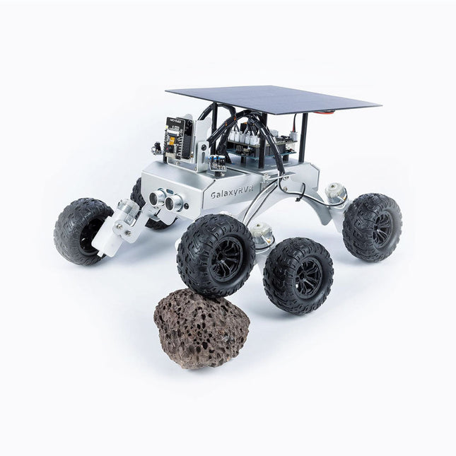
De SunFounder GalaxyRVR Mars Rover Kit is ontworpen om de functionaliteit van echte Mars-rovers na te bootsen en biedt een praktische ervaring die zowel leerzaam als opwindend is. De GalaxyRVR is compatibel met Uno R3 en is uitgerust om gemakkelijk door diverse terreinen te navigeren. Of je nu door zand, rotsen, gras of modder rijdt, deze stevige rover van aluminiumlegering, gemodelleerd met een rocker-bogie-ophangingssysteem, zorgt voor een soepele en naadloze verkenning.
Wat de GalaxyRVR onderscheidt, is het innovatieve ontwerp op zonne-energie. Met een ingebouwd zonnepaneel en een oplaadbare batterij biedt de rover een langere werkingsduur en worden tegelijkertijd milieuvriendelijke energieoplossingen omarmd. In combinatie met een ESP32 CAM en een intuïtieve app levert het een realtime First-Person View (FPV)-ervaring op, waarbij je wordt ondergedompeld in de reis van de rover terwijl je hem vanaf vrijwel elke locatie op afstand bestuurt.
Slimme navigatie vormt de kern van de GalaxyRVR. De ultrasone en infraroodsensoren maken nauwkeurige detectie en vermijding van obstakels mogelijk, waardoor ononderbroken verkenning mogelijk is. Om de veelzijdigheid te vergroten, maken levendige RGB-lichtstrips en ESP32-gestuurde LED-verlichting het mogelijk om vol vertrouwen te navigeren bij weinig licht, waardoor het pad van de rover wordt verlicht en een vleugje briljantheid aan zijn avonturen wordt toegevoegd.
De kit bevat gedetailleerde online tutorials (beschikbaar in het Engels, Duits, Frans, Spaans, Italiaans en Japans), stapsgewijze videolessen en toegang tot een ondersteunend communityforum.
Kenmerken
Gebouwd met een duurzaam frame van aluminiumlegering en een uniek rocker-bogie-systeem, kan deze rover moeiteloos diverse terreinen aan.
Zonne-energie en uitgerust met een ESP32 CAM voor realtime FPV-beelden.
Intelligente sensoren zorgen voor een soepele navigatie rond obstakels.
Specificaties
Mainboard
SunFounder Uno R3
Wifi
ESP32 CAM
Programmeertaal
C++
Controlemethode
App-controller
Invoermodules
Ultrasone sensor, sensor voor het vermijden van obstakels
Uitvoermodules
WS2812 RGB board
Batterijduur
130 minuten
Oplaadmethoden
Opladen via zonne-energie, USB-C
Functies
Klim erover, FPV, obstakel vermijden, verlichting, stembesturing
Materiaal
Aluminiumlegering
Downloads
Online Tutorial
De RedBoard Artemis Nano is een minimale maar handige implementatie van de Artemis module. Een lichtgewicht, 0.8mm dikke PCB, met onboard LiPo-batterij opladen en een Qwiic connector, dit bord is eenvoudig te implementeren in kleine projecten. Een dubbele rij massa-aansluitingen maakt het gemakkelijk om veel knoppen, LED's, en alles wat zijn eigen GND-aansluiting nodig heeft toe te voegen. Tegelijkertijd is het bord breadboard-compatibel als u de binnenste rijen pennen soldeert. Een moderne USB-C connector maakt programmeren eenvoudig. De Nano is volledig compatibel met de Arduino-kern van SparkFun en kan eenvoudig onder de Arduino IDE worden geprogrammeerd. We hebben ook de JTAG-connector blootgelegd voor meer geavanceerde gebruikers die liever de kracht en snelheid van professionele tools gebruiken. Als u op zoek bent naar een eenvoudig, kosteneffectief bord om uw verouderde Arduino Uno of Arduino Nano te vervangen, zoek dan niet verder. We hebben zelfs een digitale MEMS microfoon toegevoegd voor mensen die willen experimenteren met always-on spraakcommando's met TensorFlow en machine learning. Met 1MB flash en 384k RAM, heb je genoeg ruimte voor je schetsen. De Artemis module draait op 48MHz met een 96MHz turbo mode beschikbaar en met Bluetooth om te starten! Features 17 GPIO - allemaal geschikt voor interrupts 8 ADC kanalen met 14-bit precisie 17 PWM kanalen 2 UART's 4 I²C-bussen 2 SPI-bussen PDM Digitale Microfoon Qwiic Aansluiting
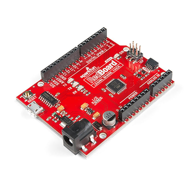
Features ATmega328 microcontroller met Optiboot Bootloader R3 Shield Compatible CH340C serieel-USB-converter 3.3 V tot 5 V Spanningsniveau Jumper A4 / A5 jumpers AP2112 spanningsregelaar ISP-kopje Ingangsspanning: 7 V - 15 V 1 Qwiic aansluiting 16 MHz kloksnelheid 32 k Flash-geheugen Alle SMD constructie verbeterde resetknop
This multifunction device combines a dual-channel oscilloscope, multimeter, and waveform generator into one unit. It features a 3.5-inch high-resolution, high-contrast color LCD display, making it suitable for outdoor use.
The device is powered by an integrated 18650 lithium battery and includes a USB-C interface, supporting power bank charging and PC software connection.
Additionally, it has a self-calibration function and supports SCPI (Standard Commands for Programmable Instruments), facilitating secondary development.
Specificaties (oscilloscoop)
Model
HDS307S
HDS310S
Bandwidth
70 MHz
100 MHz
Channels
2+1 (Signal Generator)
Sample rate
250 MSa/s
500 MSa/s
Acquisition model
Sample, Peak detect
Record length
8K
Display
3.5 inch LCD
Waveform refresh rate
10000 wfrms/s
Input coupling
DC, AC, Ground
Input impedance
1 MΩ ±2%, in parallel with 16 pF ±10 pF
Probe attenuation
1X, 10X, 100X, 1000X, 10000X
Max. input voltage
400 V (DC+AC, PK - PK)
Bandwidth limit (typical)
20 MHz / Full bandwidth
Sampling rate range
5ns/div ~ 1000s/div, step by 1 – 2 - 5
Sensitivity Resolution
10mV/div~10V/div
Low Frequency(-3db)
≥10 Hz (at input, AC coupling)
Rise time (at input, Typical)
≤5ns
≤3.5ns
Trigger type
Edge
Trigger model
Auto, Normal, Single
Trigger level range
±4 div from the screen center
Automatic measurement
Period, Frequency, Mean, PK-PK, Max, Min, RMS, Rise Time, Fall Time, +Width, -Width
Cursor measurement
ΔV, ΔT
Communication interface
USB-C
Specificaties (multimeter)
Full scale reading
4 1/2 digitals(max 20000 Counts)
Testing Modes
Voltage, Current, Resistance, Capacitance, Diode, Continuity
Maximum Input Voltage
AC 750 VDC 1000 V
Maximum Input Current
DC: 10 AAC: 10 A
Diodes Test
0-2 V
Specificaties (signaalgenerator)
Frequency Output
Sine
0.1 Hz~30 MHz
Square
0.1 Hz~6 MHz
Ramp
0.1 Hz~1 MHz
Pulse
0.1 Hz~5 MHz
Arbitrary Waveform
0.1 Hz~5 MHz
Sample Rate
125 MSa/s
Channel
1
Amplitude
20 mVpp-5 Vpp (high impedance)10 mVpp-2.5 Vpp (50 Ω)
Waveform length
8K
Vertical resolution
14 bits
Load impedance
1 MΩ/50 Ω
Inbegrepen
1x OWON HDS310S
2x Passive probes
1x Crocodile clip cable
2x Multimeter probes (1x red and 1x black)
1x Probe correction adjustment knife
1x USB cable
1x Manual
Downloads
Specifications
Quick Guide
Manual
The OWON SPE6103 is a 1-channel DC power supply (300 W) in a small body with features like over voltage and over current protection. It has a high resolution of 10 mV/1 mA. The 2.8' LCD displays the following information (constant voltage output, constant current output, cumulative running time, actual output power, channel output status, actual voltage output, actual current output).Features
Small body for easy carry
High resolution: 10 mV/1 mA
List waveform editing output, editable 10 groups of timing output function
Low ripple/noise
Over voltage / over current protection
Output voltage and current curve monitoring function
Intelligent temperature control fan cooling
2.8-inch TFT LCD display
USB communication interface, support SCPI
Specifications
Model
SPE6102
SPE6103
Rated Output (0-40°C)
Voltage
0-60 V
0-60 V
Current
10 A
10 A
Output Power
200 W
300 W
USB Output
5 V/1 A (SPE Series) or suppout QC2.0, QC3.0, BC1.2, Apple, Huawei, Samsung fast charging protocols (optional)
Load Regulation
Voltage
?30 mV
Current
?20 mA
Power Regulation
Voltage
?30 mV
Current
?20 mA
Setting Resolution
Voltage
10 mV
Current
1 mA
Readback Resolution
Voltage
10 mV
Current
1 mA
Value Resolution (within 12 months) (25 ±5°C)
Voltage
?0.1% ±30 mV
?0.1% ±30 mV
Current
?0.05% ±10 mA
Readback Value Resolution (25 ±5°C)
Voltage
?0.1% ±30 mV
?0.1% ±30 mV
Current
Ripple/Noise
Voltage (Vp-p)
?50mVp-p
?50mVp-p
Voltage (rms)
?5mVrms
?5mVrms
Current (rms)
?30mAp-p
Output temperature coefficient (0-40°C)
Voltage
100ppm/°C
Current
200ppm/°C
Readback temperature coefficient
Voltage
100ppm/°C
Current
200ppm/°C
Response Time (50-100% rated load)
?1.0ms
Storage
4 groups of data
Working Temperature
0-40°C
Included
1x OWON SPE6102
1x Power Cord
1x Quick Guide
1x USB Cable
1x Fuse
Downloads
User Manual
Programming Manual
Software
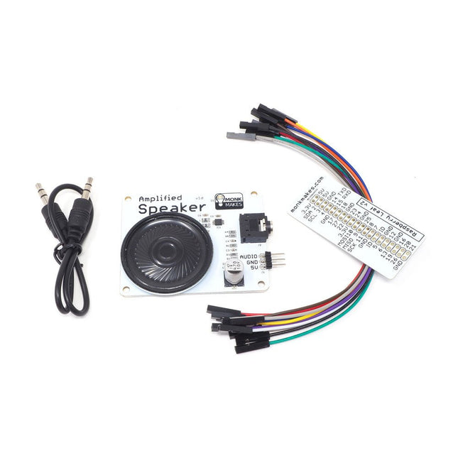
The Speaker Kit for Raspberry Pi is a small amplified speaker designed for the Raspberry Pi. Included MonkMakes Amplified Speaker Set of 10 female to female header wires Short stereo audio lead Raspberry Leaf GPIO template Downloads Instructions Datasheet
Kenmerken Capacitieve meetplaat (corrosiebestendig) Geïntegreerde waterpomp met een vermogen van 5 W LEGO compatibele gaten Applicaties Plantenteelt Bodemvochtdetectie Slimme irrigatie Inbegrepen 1x bewateringsunit 2x aanzuigbuis 1x HY2.0-4P kabel Pomp vermogen 5 W Gewicht 78 gr Afmetingen 192.5 mm x 24 mm x 33 mm
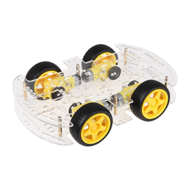
Stap zonder complicaties en tegen een redelijke prijs in de wereld van de robotica met de Car Kit 01 voor Arduino. Dit is een kit die kan worden gebruikt als een basis framework voor een auto/robot. De set is zeer eenvoudig in elkaar te zetten en in een mum van tijd klaar voor gebruik. De meegeleverde motorreductoren (met dubbele as) kunnen worden gebruikt in een spanningsbereik van 3 tot 9 volt. Het toerental varieert tussen 90 en 300 omwentelingen per minuut. Het koppel (gf/cm) tussen 800 en 1200. De Car Kit is compatibel met alle Arduino boards. Note: U zult ook andere componenten moeten toevoegen zoals een stroombron (batterijen) en een controller zoals een Arduino met een motor controller. De bodemplaat bevat al de gaten voor de montage van een Arduino. Gebruikershandleiding
Heeft u een eenvoudige AI-camera nodig om uw projecten te verbeteren?
Het intuïtieve ontwerp van de HuskyLens AI-camera stelt de gebruiker in staat om verschillende aspecten van de camera te bedienen door gewoon op knoppen te drukken. U kunt het leren van nieuwe objecten starten en stoppen en zelfs schakelen tussen algoritmes vanaf het apparaat.
Om de noodzaak van aansluiting op een pc verder te verminderen, wordt de HuskyLens AI Camera geleverd met een 2-inch display, zodat u in realtime kunt zien wat er gaande is.
Specificaties
Processor: Kendryte K210
Beeldsensor: OV2640 (2.0 Megapixel Camera)
Voedingsspanning: 3,3~5,0 V
Stroomverbruik (TYP): 320 mA bij 3,3 V, 230 mA bij 5,0 V (gezichtsherkenningsmodus; 80% helderheid achtergrondverlichting; vullicht uit)
Aansluitingsinterface: UART, I²C
Display: 2,0-inch IPS-scherm met 320x240 resolutie
Ingebouwde algoritmen: Gezichtsherkenning, Object Tracking, Object Recognition, Line Tracking, Kleurherkenning, Tag Recognition
Afmeting: 52 x 44,5 mm
Inbegrepen
1x HuskyLens moederbord
1x M3 Schroeven
1x M3 Moeren
1x Kleine montagebeugel
1x Verhoogingsbeugel
1x Zwaartekracht 4-Pin Sensor Kabel
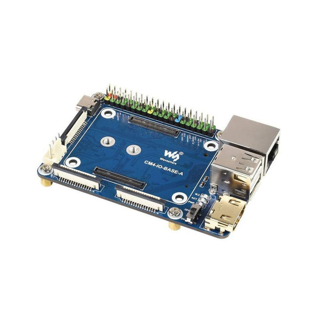
Specifications CM4 socket Suitable for all variants of Compute Module 4 Networking Gigabit Ethernet RJ45 connectorM.2 M KEY, supports communication modules or NVME SSD Connector Raspberry Pi 40-PIN GPIO header USB 2x USB 2.0 Type A2x USB 2.0 via FFC connector Display MIPI DSI display port (15-pin 1.0 mm FPC connector) Camera 2x MIPI CSI-2 camera port (15-pin 1.0 mm FPC connector) Video 2x HDMI port (including one port via FFC connector), supports 4K 30fps output RTC N/A Storage MicroSD card socket for Compute Module 4 Lite (without eMMC) variants Fan header No fan control, 5 V Power input 5 V Dimensions 85 x 56 mm Included 1x CM4-IO-BASE-A 1x SSD mounting screw Downloads Wiki
The UDP3305S-E is a high-performance programmable linear DC power supply. It has a clear LCD user interface, excellent performance indicators, a variety of analysis functions and communication interfaces. It can meet the diversified test needs of users. It aims to provide cost-effective DC programmable power supply equipment for teaching, scientific research, industry and other fields.
LCD interactive interface
Using a 4.3-inch high-definition display screen, it provides users with a man-machine interface with rich functions and simple operation, which can display the current set output voltage/current, actual output voltage/current and protection output voltage/current value of the power supply in real time. The functional interface is simple and comprehensive, easy to operate.
One-key setting for series and parallel
The series-parallel connection between CH1 and CH2 of the main channel can be realized without external connection, which simplifies the connection and makes the test easier.
List/Delayer function
With list and delay setting functions, it can set up to 2048 sets of data according to test requirements, and the number of cycles can reach 99999. It is used with waveform templates, which is very convenient for cycle testing and aging testing.
Rich remote control interface
Standard RS232 communication interface, Ethernet interface, Digital I/O and master and slave USB interfaces, can be controlled by remote connection to Ethernet, or through RS232 and USB, with the host computer software to achieve software control.
Specificaties
Type
Linear DC power supply
Channels
4
Total power
328 W
Output voltage
CH1/CH2: 0~30 VCH3: 0~6 VCH4: 5 V
Output current
CH1/CH2: 0~5 ACH3: 0~3 ACH4: 2 A
Resolution
10 mV, 1 mA
Setting accuracy
0.3% +20 mV<0.2% +5 mA
Connectivity
USB Device, RS-232, LAN, USB host, Digital I/O
Inbegrepen
1x UDP3305S-E DC Power Supply
1x Power cord
1x USB cable
Downloads
Datasheet
User manual
Programming manual
Software V1.0
Firmware V1.10
De Ulanzi TC001 is een LED pixelklok bestaande uit 256 individueel adresseerbare RGB LED's (8x32), met ingebouwde accu, zoemer, licht-, temperatuur- en vochtigheidssensor. De geïntegreerde oplaadbare accu biedt een gebruikstijd van maximaal 5 uur. De WiFi-verbinding met de klok wordt gemaakt via een ESP32-chip. De Ulanzi TC001 maakt gebruik van een ESP32-WROOM-32D module.
Kenmerken
Pixel weergave.
Gelijktijdige weergave van het aantal volgers: groei van het aantal fans is direct zichtbaar, geschikt voor YouTube, Bilibili en Weibo.
Pomodoro Clock Design: beheer je eigen tijd op een meer wetenschappelijke wijze.
Ontdek de onbegrensde mogelijkheden: er kunnen meerdere programma's via de besturingsserver worden geïnstalleerd om meerdere functies te creëren.
Awtrix maakt het beter: de Awtrix simulator in de firmware van de TC001 simuleert een Awtrix matrix, en stelt u in staat om de klok te besturen met behulp van een standaard Awtrix host.
Een hi-tech en indrukwekkend uiterlijk: eenvoudig de juiste sfeer te creëren, een LED-kleuren pixelscherm met een beter beeld.
Een ingebouwde 4400 mAh accu met een accu gebruiksduur tot 5 uur.
Specificaties
Aantal LED's: 256 (8x32)
Bedrijfsspanning: 3,7 V
Verbruik: 3 W
Accu capaciteit: 4400 mAh
Interface: USB-C
Afmetingen: 200,6 x 70,3 x 31,9 mm
Gewicht: 283 g
Inbegrepen
Ulanzi TC001 Smart Pixel Clock
USB-kabel
Handleiding
Downloads
Firmware
Een moderne USB-C connector maakt programmeren eenvoudig. Naast de naar buiten gevoerde pinnen zijn er twee aparte I2C-poorten met Qwiic-ondersteuning, zodat u gemakkelijk Qwiic-apparaten in serie kunt schakelen. We hebben de SWD-pinnen bereikbaar gemaakt voor meer geavanceerde gebruikers die liever de kracht en snelheid van professionele gereedschappen gebruiken. Een USB-A-aansluiting is voorzien voor processorkaarten met USB Host-ondersteuning. Een backupbatterij is toegevoegd voor processorkaarten met RTC. Als u 'veel' GPIO's nodig hebt met een eenvoudig te programmeren, kant-en-klare module, dan is de ATP de oplossing die u nodig hebt. We hebben zelfs een handige jumper toegevoegd om het stroomverbruik te meten. Eigenschappen M.2 Connector Ingangsspanning ~3.3 V to 6.0 V (via VIN naar AP7361C 3.3V spanningsregelaar) 3.3 V (via 3V3) Ports [1] 1 x USB type C 1 x USB type A Host 2 x Qwiic Enabled I2C 1 x CAN 1 x I2S 2 x SPI 2 x UARTs 2 x Dedicated Analog Pins 2 x Dedicated PWM Pins 2 x Dedicated Digital Pins 12 x General Purpose Input Output Pins 1 x SWD 2x5 header 1 mAh battery backup voor RTC Druktoetsen Reset Boot LEDs Power 3.3 V M2.5x3mm kruiskopschroef