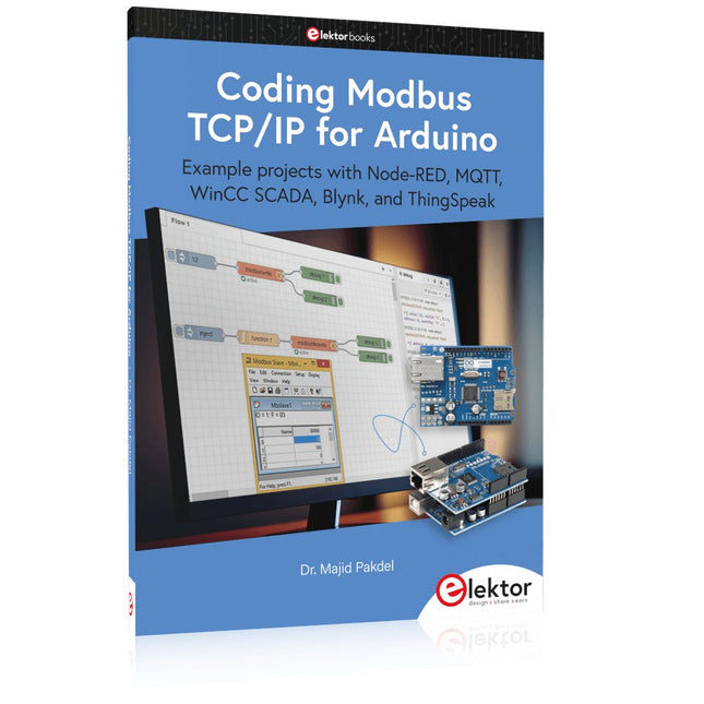
Example projects with Node-RED, MQTT, WinCC SCADA, Blynk, and ThingSpeak
This comprehensive guide unlocks the power of Modbus TCP/IP communication with Arduino. From the basics of the Modbus protocol right up to full implementation in Arduino projects, the book walks you through the complete process with lucid explanations and practical examples.
Learn how to set up Modbus TCP/IP communication with Arduino for seamless data exchange between devices over a network. Explore different Modbus functions and master reading and writing registers to control your devices remotely. Create Modbus client and server applications to integrate into your Arduino projects, boosting their connectivity and automation level.
With detailed code snippets and illustrations, this guide is perfect for beginners and experienced Arduino enthusiasts alike. Whether you‘re a hobbyist looking to expand your skills or a professional seeking to implement Modbus TCP/IP communication in your projects, this book provides all the knowledge you need to harness the full potential of Modbus with Arduino.
Projects covered in the book:
TCP/IP communication between two Arduino Uno boards
Modbus TCP/IP communication within the Node-RED environment
Combining Arduino, Node-RED, and Blynk IoT cloud
Interfacing Modbus TCP/IP with WinCC SCADA to control sensors
Using MQTT protocol with Ethernet/ESP8266
Connecting to ThingSpeak IoT cloud using Ethernet/ESP8266
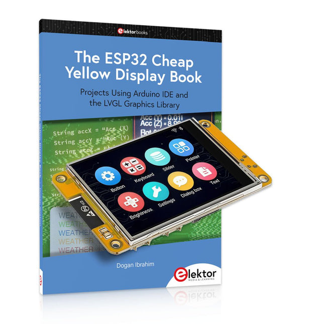
Meer dan 40 volledig geteste ESP32-projecten met Arduino IDE en de LVGL grafische bibliotheek
Deze bundel bevat de ESP32 Cheap Yellow Display (CYD) – een compact ontwikkelbord dat een standaard ESP32-microcontroller combineert met een TFT-kleurendisplay van 320 x 240 pixels. Het bord beschikt ook over meerdere aansluitingen voor GPIO, seriële communicatie (TX/RX), voeding en aarde. Het ingebouwde display is een groot voordeel, omdat gebruikers hiermee complexe, grafische projecten kunnen maken zonder dat er externe LCD's of displays nodig zijn.
Het bijbehorende boek introduceert de hardware en de ingebouwde aansluitingen van het CYD-bord in detail. Het biedt een reeks projecten van beginners- tot gevorderdenniveau, ontwikkeld met de populaire Arduino IDE 2.0. Zowel basis grafische functies als de krachtige LVGL grafische bibliotheek worden behandeld, met praktische projecten die elke aanpak illustreren.
Alle meegeleverde projecten zijn volledig getest en klaar voor gebruik. Het boek bevat blokdiagrammen, circuitschema's, complete codelijsten en stapsgewijze uitleg. Met de LVGL-bibliotheek kunnen lezers moderne, kleurrijke grafische interfaces maken met behulp van widgets zoals knoppen, labels, schuifregelaars, kalenders, toetsenborden, grafieken, tabellen, menu's, animaties en meer.
ESP32 Cheap Yellow Display Board
Dit ontwikkelbord (ook bekend als "Cheap Yellow Display") wordt aangedreven door de ESP-WROOM-32, een dual-core MCU met geïntegreerde Wi-Fi- en Bluetooth-mogelijkheden. Het werkt op een hoofdfrequentie tot 240 MHz, met 520 KB SRAM, 448 KBROM en 4 MB Flash-geheugen. Het bord is voorzien van een 2,8-inch scherm met een resolutie van 240 x 320 en resistieve aanraking.
Bovendien bevat het bord een achtergrondverlichtingsbesturingscircuit, aanraakbesturingscircuit, luidsprekeraandrijfcircuit, lichtgevoelig circuit en RGB-LED-besturingscircuit. Het biedt ook een TF-kaartsleuf, seriële interface, DHT11 temperatuur- en vochtigheidssensorinterface en extra IO-poorten.
De module ondersteunt ontwikkeling in Arduino IDE, ESP-IDE, MicroPython en Mixly.
Toepassingen
Beeldoverdracht voor Smart Home-apparaat
Draadloze bewaking
Slimme landbouw
Draadloze QR-herkenning
Signaal van draadloos positioneringssysteem
En andere IoT-toepassingen
Specificaties
Microcontroller
ESP-WROOM-32 (Dual-core MCU met geïntegreerde Wi-Fi en Bluetooth)
Frequentie
Tot 240 MHz (rekenkracht is maximaal 600 DMIPS)
SRAM
520 KB
ROM
448 KB
Flash
4 MB
Bedrijfsspanning
5 V
Stroomverbruik
ca. 115 mA
Display
2,8" TFT-kleurenscherm (240 x 320)
Touch
Resistief Touch
Driver chip
ILI9341
Afmetingen
50 x 86 mm
Gewicht
50 g
Downloads
GitHub
Inhoud van de bundel
The ESP32 Cheap Yellow Display Book (normale prijs: € 35)
ESP32 Cheap Yellow Display Board (normale prijs: € 25)
1x ESP32 Dev Board met 2,8" display en acryl-behuizing
1x Touchpen
1x Aansluitkabel
1x USB-kabel
Example projects with Node-RED, MQTT, WinCC SCADA, Blynk, and ThingSpeak
This comprehensive guide unlocks the power of Modbus TCP/IP communication with Arduino. From the basics of the Modbus protocol right up to full implementation in Arduino projects, the book walks you through the complete process with lucid explanations and practical examples.
Learn how to set up Modbus TCP/IP communication with Arduino for seamless data exchange between devices over a network. Explore different Modbus functions and master reading and writing registers to control your devices remotely. Create Modbus client and server applications to integrate into your Arduino projects, boosting their connectivity and automation level.
With detailed code snippets and illustrations, this guide is perfect for beginners and experienced Arduino enthusiasts alike. Whether you‘re a hobbyist looking to expand your skills or a professional seeking to implement Modbus TCP/IP communication in your projects, this book provides all the knowledge you need to harness the full potential of Modbus with Arduino.
Projects covered in the book:
TCP/IP communication between two Arduino Uno boards
Modbus TCP/IP communication within the Node-RED environment
Combining Arduino, Node-RED, and Blynk IoT cloud
Interfacing Modbus TCP/IP with WinCC SCADA to control sensors
Using MQTT protocol with Ethernet/ESP8266
Connecting to ThingSpeak IoT cloud using Ethernet/ESP8266
Projects Using Arduino IDE and the LVGL Graphics Library
The ESP32 is probably one of the most popular microcontrollers used by many people, including students, hobbyists, and professional engineers. Its low cost, coupled with rich features makes it a popular device to use in many projects. Recently, a board called the ESP32 Cheap Yellow Display (CYD for short) is available from its manufacturers. The board includes a standard ESP32 microcontroller together with a 320x240 pixel TFT display. Additionally, the board provides several connectors for interfaces such as GPIO, serial port (TX/RX), power and Ground. The inclusion of a TFT display is a real advantage as it enables users to design complex graphics-based projects without resorting to an external LCD or graphics displays.
The book describes the basic hardware of the ESP32 CYD board and provides details of its on-board connectors. Many basic, simple, and intermediate-level projects are given in the book based on the ESP32 CYD, using the highly popular Arduino IDE 2.0 integrated development environment. The use of both the basic graphics functions and the use of the popular LVGL graphics library are discussed in the book and projects are given that use both types of approaches.
All the projects given in the book have been tested and are working. The block diagram, circuit diagram, and the complete program listings and program descriptions of all the projects are given with explanations. Readers can use the LVGL graphics library to design highly popular eye-catching full-color graphics projects using widgets such as buttons, labels, calendars, keypads, keyboards, message boxes, spinboxes, sliders, charts, tables, menus, bars, switches, drop-down lists, animations, and many more widgets.
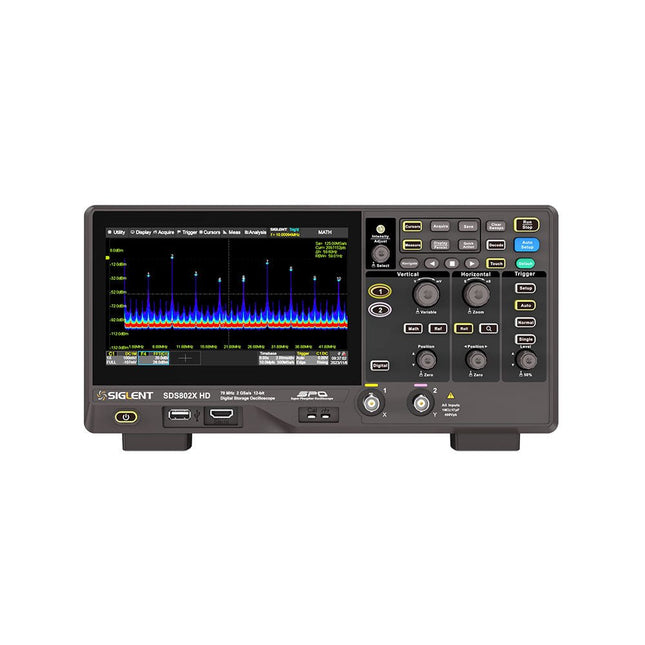
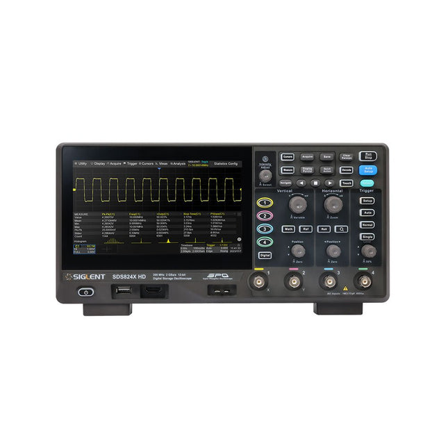
The Siglent SDS822X HD digital storage oscilloscope is based on 2 GSa/s, 12-bit Analog-Digital Converters and front ends with excellent noise floor performance. With a 200 MHz bandwidth, and a maximum record length of 100 Mpts, and the capability to analyze 2 analog channels alongside 16 digital channels, the SDS822X HD is perfectly suited for mixed signal analysis.
Kenmerken
12-bit High Resolution
12-bit Analog-Digital Convertors with sample rate up to 2 GSa/s
Front ends with 70 μVrms noise floor @ 200 MHz bandwidth
2/4 analog channels, up to 700 MHz bandwidth
SPO technology
Waveform capture rate up to 120,000 wfm/s (normal mode), and 500,000 wfm/s (sequence mode)
Supports 256-level intensity grading and color temperature display modes.
Up to 50 Mpts record length
Digital trigger system
Intelligent trigger: Edge, Slope, Pulse width, Window, Runt, Interval, Dropout, Pattern, Video (HDTV supported), Qualified, Nth edge, Delay, Setup/Hold time.
Serial bus triggering and decoder, supports protocols I²C, SPI, UART, CAN, LIN.
Segmented acquisition (Sequence) mode, dividing the maximum record length into multiple segments (up to 80,000), according to trigger conditions set by the user, with a very small dead time between segments to capture the qualifying event.
History waveform record (History) function, the maximum recorded waveform length is 80,000 frames.
Automatic measurements on 50+ parameters, supports statistics with histogram, track, trend, Gating measurement, and measurements on Math, History and Ref.
4 Math traces (2 Mpts FFT, addition, subtraction, multiplication, division, integration, differential, square root, etc.), supports formula editor.
Abundant data analysis functions such as Search, Navigate, Counter, Bode plot and Power Analysis
High Speed hardware-based Mask Test function, with Mask Editor tool for creating user-defined masks
16 digital channels (optional)
25 MHz waveform generator (optional)
7" TFT-LCD display with 1024 x 600 resolution; Capacitive touch screen supports multi-touch gestures.
Interfaces include: USB Hosts, USB Device (USBTMC), LAN (VXI-11/Telnet/Socket), Pass/Fail, Trigger Out
Built-in web server supports remote control over the LAN port using a web browser. Supports SCPI remote control commands. Supports external mouse and keyboard. Supports NTP.
Specificaties
Analog Channels
2
Bandwidth
200 MHz
Vertical resolution
12-bit
Sample rate (Max.)
One channel mode: 100 Mpts/chTwo channel mode: Mpts/chFour channel mode: 25 Mpts/ch
Memory depth (Max.)
One channel mode: 50 Mpts/chTwo channel mode: 25 Mpts/ch
Waveform capture rate (Max.)
Normal mode: 120,000 wfm/sSequence mode: 500,000 wfm/s
Trigger type
Edge, Slope, Pulse width, Window, Runt, Interval, Dropout, Pattern, Video, Qualified, Nth edge, Delay, Setup/Hold time, Serial
Serial trigger and decode (Standard)
I²C, SPI, UART, CAN, LIN
Measurement
50+ parameters, statistics, histogram, trend, and track supported
Math
4 traces 2 Mpts FFT, Filter, +, -, x, ÷, ∫dt, d/dt, √, Identity, Negation, Absolute, Sign, ex, 10x, ln, lg, Interpolation, MaxHold, MinHold, ERES, Average. Supports formula editor
Data analysis
Search, Navigate, History, Mask Test, Counter, Bode plot, and Power Analysis
Digital channel (optional)
16-channel; maximum sample rate up to 1 GSa/s; record length up to 10 Mpts
USB AWG module (option)
One channel, 25 MHz, sample rate of 125 MHz, wave length of 16 kpts, isolated output
I/O
2x USB 2.0 Host, USB 2.0 Device, 10/100 M LAN, Auxiliary output (TRIG OUT, PASS/FAIL), SBUS (Siglent MSO)
Probe (Standard)
Passive probe PB470 for each channel
Display
7 TFT-LCD with capacitive touch screen (1024x600)
Inbegrepen
1x Siglent SDS822X Oscilloscope
2x Passive probe (200 MHz) PP520
1x Power cord (EU)
1x USB cable
1x Certificate of calibration
1x Quick start
Downloads
Datasheet
Manual
Programming guide
The Siglent SDS814X HD digital storage oscilloscope is based on 2 GSa/s, 12-bit Analog-Digital Converters and front ends with excellent noise floor performance. With a 100 MHz bandwidth, and a maximum record length of 50 Mpts, and the capability to analyze 4 analog channels alongside 16 digital channels, the SDS814X HD is perfectly suited for mixed signal analysis.
Kenmerken
12-bit High Resolution
12-bit Analog-Digital Convertors with sample rate up to 2 GSa/s
Front ends with 70 μVrms noise floor @ 100 MHz bandwidth
2/4 analog channels, up to 700 MHz bandwidth
SPO technology
Waveform capture rate up to 80,000 wfm/s (normal mode), and 500,000 wfm/s (sequence mode)
Supports 256-level intensity grading and color temperature display modes.
Up to 50 Mpts record length
Digital trigger system
Intelligent trigger: Edge, Slope, Pulse width, Window, Runt, Interval, Dropout, Pattern, Video (HDTV supported), Qualified, Nth edge, Delay, Setup/Hold time.
Serial bus triggering and decoder, supports protocols I²C, SPI, UART, CAN, LIN.
Segmented acquisition (Sequence) mode, dividing the maximum record length into multiple segments (up to 80,000), according to trigger conditions set by the user, with a very small dead time between segments to capture the qualifying event.
History waveform record (History) function, the maximum recorded waveform length is 80,000 frames.
Automatic measurements on 50+ parameters, supports statistics with histogram, track, trend, Gating measurement, and measurements on Math, History and Ref.
4 Math traces (2 Mpts FFT, addition, subtraction, multiplication, division, integration, differential, square root, etc.), supports formula editor.
Abundant data analysis functions such as Search, Navigate, Counter, Bode plot and Power Analysis
High Speed hardware-based Mask Test function, with Mask Editor tool for creating user-defined masks
16 digital channels (optional)
25 MHz waveform generator (optional)
7" TFT-LCD display with 1024 x 600 resolution; Capacitive touch screen supports multi-touch gestures.
Interfaces include: USB Hosts, USB Device (USBTMC), LAN (VXI-11/Telnet/Socket), Pass/Fail, Trigger Out
Built-in web server supports remote control over the LAN port using a web browser. Supports SCPI remote control commands. Supports external mouse and keyboard. Supports NTP.
Specificaties
Analog Channels
4
Bandwidth
100 MHz
Vertical resolution
12-bit
Sample rate (Max.)
One channel mode: 2 GSa/sTwo channel mode: 1 GSa/sFour channel mode: 500 MSa/s
Memory depth (Max.)
One channel mode: 50 Mpts/chTwo channel mode: 25 Mpts/chFour channel mode: 10Mpts/ch
Waveform capture rate (Max.)
Normal mode: 80,000 wfm/sSequence mode: 500,000 wfm/s
Trigger type
Edge, Slope, Pulse width, Window, Runt, Interval, Dropout, Pattern, Video, Qualified, Nth edge, Delay, Setup/Hold time, Serial
Serial trigger and decode (Standard)
I²C, SPI, UART, CAN, LIN
Measurement
50+ parameters, statistics, histogram, trend, and track supported
Math
4 traces 2 Mpts FFT, Filter, +, -, x, ÷, ∫dt, d/dt, √, Identity, Negation, Absolute, Sign, ex, 10x, ln, lg, Interpolation, MaxHold, MinHold, ERES, Average. Supports formula editor
Data analysis
Search, Navigate, History, Mask Test, Counter, Bode plot, and Power Analysis
Digital channel (optional)
16-channel; maximum sample rate up to 1 GSa/s; record length up to 10 Mpts
USB AWG module (option)
One channel, 25 MHz, sample rate of 125 MHz, wave length of 16 kpts, isolated output
I/O
2x USB 2.0 Host, USB 2.0 Device, 10/100 M LAN, Auxiliary output (TRIG OUT, PASS/FAIL), SBUS (Siglent MSO)
Probe (Standard)
Passive probe PB470 for each channel
Display
7 TFT-LCD with capacitive touch screen (1024x600)
Inbegrepen
1x Siglent SDS814X Oscilloscope
4x Passive probe (100 MHz) PP510
1x Power cord (EU)
1x USB cable
1x Certificate of calibration
1x Quick start
Downloads
Datasheet
Manual
Programming guide
Projects Using Arduino IDE and the LVGL Graphics Library
The ESP32 is probably one of the most popular microcontrollers used by many people, including students, hobbyists, and professional engineers. Its low cost, coupled with rich features makes it a popular device to use in many projects. Recently, a board called the ESP32 Cheap Yellow Display (CYD for short) is available from its manufacturers. The board includes a standard ESP32 microcontroller together with a 320x240 pixel TFT display. Additionally, the board provides several connectors for interfaces such as GPIO, serial port (TX/RX), power and Ground. The inclusion of a TFT display is a real advantage as it enables users to design complex graphics-based projects without resorting to an external LCD or graphics displays.
The book describes the basic hardware of the ESP32 CYD board and provides details of its on-board connectors. Many basic, simple, and intermediate-level projects are given in the book based on the ESP32 CYD, using the highly popular Arduino IDE 2.0 integrated development environment. The use of both the basic graphics functions and the use of the popular LVGL graphics library are discussed in the book and projects are given that use both types of approaches.
All the projects given in the book have been tested and are working. The block diagram, circuit diagram, and the complete program listings and program descriptions of all the projects are given with explanations. Readers can use the LVGL graphics library to design highly popular eye-catching full-color graphics projects using widgets such as buttons, labels, calendars, keypads, keyboards, message boxes, spinboxes, sliders, charts, tables, menus, bars, switches, drop-down lists, animations, and many more widgets.
Learn to program displays and GUIs with Python
This book is about Raspberry Pi 4 display projects. The book starts by explaining how to install the latest Raspbian operating system on an SD card, and how to configure and use the GPIO ports.
The core of the book explains the following topics in simple terms with fully tested and working example projects:
Simple LED projects
Bar graph LED projects
Matrix LED projects
Bitmap LED projects
LED strips
LCDs
OLED displays
E-paper displays
TFT displays
7-inch touch screen
GUI Programming with Tkinder
One unique feature of this book is that it covers almost all types of display that readers will need to use in their Raspberry Pi based projects. The operation of each project is fully given, including block diagrams, circuit diagrams, and commented full program listings. It is therefore an easy task to convert the given projects to run on other popular platforms, such as Arduino or PIC microcontrollers.
Python program listings of all Raspberry Pi projects developed in this book are available for download at Elektor.com. Readers can use these programs in their projects. Alternatively, they can modify the programs to suit their applications.
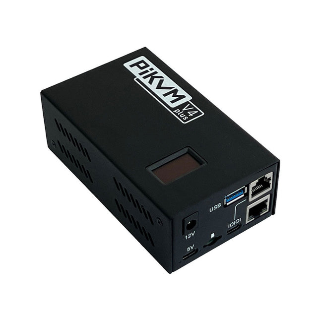
PiKVM is een open-source, hoogkwalitatief, op Raspberry Pi gebaseerd KVM over IP-apparaat met veel mogelijkheden. Het maakt het mogelijk om servers of werkstations op afstand te bedienen, ongeacht de status van het besturingssysteem en of er een is geïnstalleerd. Met PiKVM kun je je computer aan- en uitzetten of opnieuw starten, het UEFI/BIOS configureren en zelfs het besturingssysteem opnieuw installeren met behulp van de virtuele cd-rom of flashdrive. Je kunt je toetsenbord en muis op afstand gebruiken of PiKVM kan een toetsenbord, muis en monitor simuleren, die dan in een webbrowser worden weergegeven alsof je op afstand direct op een systeem werkt.
PiKVM V4 Plus is de PiKVM-versie met de meeste functies! Het is ontworpen als de meest geavanceerde en veelzijdige PiKVM en zal je helpen bij de meest unieke en complexe scenario's voor technische ondersteuning of systeemtoegang/bediening op afstand. De toekomstbestendige architectuur maakt het mogelijk om meer functies en functionaliteit toe te voegen.
Kenmerken
PiKVM V4 wordt geleverd als een compleet product, uitgerust met alles wat je nodig hebt: een voeding, USB- en Ethernetkabels en zelfs PCI-beugels om het ATX-board te installeren in een ATX- of mini ITX-computer/serverbehuizing.
Met de (meegeleverde) Raspberry Pi Compute Module 4 (CM4) maakt het mogelijk de lat op een industrieel niveau te leggen.
Verbeterde WiFi-connectiviteit met een aansluiting voor een optionele externe antenne.
Resolutieondersteuning 1920x1080 @ 60 Hz & 1920x1200 @ 60 Hz voor meer UEFI/BIOS-compatibiliteit.
Nieuwe zorgvuldig vervaardigde stalen behuizing met een glad uiterlijk, lichtgeleiders, locatiebaken, SD-kaart toegangsbeveiliging en een Kensington-beveiligingssleuf.
Specificaties
Raspberry Pi computermodule 4 (CM4)
CM4102000 met 2 GB RAM en WiFi/Bluetooth (Lite)
Type aansluiting
USB-C
Type vermogen
12 V/2 A (DC)
Optie voor stroomuitval
Interne supercondensator voor ondersteuning van de realtime klok
HDMI vrouwelijk
HDMI-broningang
USB-C vrouwelijk
Voor het toetsenbord, de muis, massaopslag en andere externe apparaat emulatie
Seriële consolebeheerpoort
Micro SD-kaartsleuf
Voor OS-opslag
ATX RJ-45
Speciale poort voor stroomregeling of AUX
WiFi
Optionele WiFi b/g/n ondersteuning met interne/externe antenne
LED-indicatoren
Voeding, activiteit, consolevoeding, zoekindicator, HDMI-bron ingeschakeld
Display
OLED 128x32 0,91" (wit)
Ondersteunde resoluties
Tot 1920x1200 @ 60 Hz
Videocompressiemethoden
MJPEG, H.264
Modus voor audio-opname
Ondersteuning voor HDMI-audio-opname
Piekverbruik
Tot 24 W (2 A/12 V)
Bedrijfstemperatuur
0-50°C
Afmetingen
120 x 68 x 44 mm
Gewicht
350 g
Modelvergelijking
PiKVM V3
PiKVM V4 Plus
Hoofdcomputer
Raspberry Pi 4 B
Raspberry Pi computermodule 4 (CM4)
1920x1200 @ 60 Hz HDMI-video-ondersteuning met geluid
✓
Verbeterde compatibiliteit voor vele UEFI en BIOS
✓
Ondersteuning voor USB-sleutel/muis/massaopslag
✓
✓
Ondersteuning voor USB-host (ondersteuning voor externe USB-apparaten)
✓
✓
Extra ondersteuning voor USB-opslag met interne installatie
✓
RJ-45 consolepoort
✓
✓
Koelsysteem
Axiale ventilator
Geavanceerd met radiale ventilator
Locatie-LED
✓
Stroomverbruik in inactieve modus
3,3 W
3,3 W
Ondersteuning voor externe antenne
WiFi/LTE
mPCI-e sleuf met USB-lijnen voor LTE/5G-kaarten
✓
Inbegrepen
PiKVM V4 Plus incl. Raspberry Pi CM4, behuizing en OLED-display
Micro-SD-kaart met voorgeïnstalleerde PiKVM-software
ATX-besturingskaart
ATX-aansluitkabels
ATX-installatiebeugels
Ethernetkabel
ATX-kabel
USB-C naar USB-A kabel
12 V/2 A voeding (internationale adapters)
Downloads
Datasheet
Documentation
Images
GitHub
The newcomer to Microchip’s PIC microcontrollers invariably gets an LED to flash as their first attempt to master this technology. You can use just a simple LED indicator in order to show that your initial attempt is working, which will give you confidence to move forward. This is how the book begins — simple programs to flash LEDs, and eventually by stages to use other display indicators such as the 7-segment display, alphanumeric liquid crystal displays and eventually a colour graphic LCD.
As the reader progresses through the book, bigger and upgraded PIC chips are introduced, with full circuit diagrams and source code, both in assembler and C.
In addition, a small tutorial is included using the MPLAB programming environment, together with the EAGLE schematic and PCB design package to enable readers to create their own designs using the book’s many case studies as working examples to work from.
Creëer bliksem met een aanraking van je vingers of een handgeklap
De Plasma Magic Ball is een geavanceerde technologische gadget en een opvallend kunstwerk. In de glazen bol creëert een speciaal gasmengsel betoverende lichteffecten wanneer het wordt geactiveerd door hoogfrequente stroom – alsof je een storm in je handen houdt.
Perfect voor gebruik thuis, op kantoor, op school, in hotels of in bars. Het is een uniek decoratief element dat nieuwsgierigheid opwekt. Op zoek naar een leuk en bijzonder cadeau? De Plasma Magic Ball is een geweldige keuze voor vrienden en familie.
Ondanks de verbluffende effecten verbruikt de Plasma Magic Ball zeer weinig elektriciteit. Het glas zelf is gemaakt van speciaal gehard, zeer sterk materiaal en is bestand tegen temperaturen tot 522°C.
Specificaties
Materiaal
Kunststof
Diameter bal
15 cm
Ingangsspanning
220 V
Uitgangsspanning
12 V
Vermogen
15 W
Afmetingen
25 x 15,5 x 15,5 cm
,
van Clemens Valens
Andonstar AD210: zeer betaalbare digitale microscoop met een 10,1 inch scherm
De digitale microscopen van Andonstar staan bekend om hun combinatie van goede prestaties en betaalbaarheid. Ze zijn gemaakt voor het elektronica lab waar ze nuttig...