Kits
-

Velleman Whadda Brain Game
4 LEDs and 4 push buttons ensure hours of fun. Repeat the combination, harder and harder, faster and faster. The microprocessor-controlled game has 4 different difficulty levels and low consumption. The sound and/or LED indication are adjustable. To save the three 1.5 V AA batteries (not included), the kit automatically switches itself off when not in use. Downloads Manual
€ 11,95€ 5,95
Leden identiek
-
Velleman Whadda Electronic Dice
This electronic dice with 7 red LEDs rolls when the push button is released and works with a 9 V battery (not included). Downloads Manual
€ 9,95€ 4,95
Leden identiek
-

SparkFun SparkFun DLI Kit
NVIDIA wil de toegankelijkheid en innovatie op het gebied van 'Deep Learning' verbeteren en heeft daarom een gratis, zelfstudie online cursus Deep Learning Institute (DLI) ontwikkeld: “Getting Started on AI with Jetson Nano.” Het doel van de cursus is om basisvaardigheden op te bouwen, zodat iedereen creatief aan de slag kan met de Jetson Developer Kit. Houd er rekening mee dat deze kit is bestemd voor degenen die al een Jetson Nano Developer Kit bezitten en willen deelnemen aan de DLI-cursus. Een Jetson Nano is niet inbegrepen in deze kit.Inbegrepen in deze kit is alles wat u nodig heeft om aan de slag te gaan in de 'Aan de slag met AI met Jetson Nano' (behalve een Jetson Nano, natuurlijk), en u zult leren hoe u Uw Jetson Nano en camera instelt Beeldgegevens verzamelt voor classificatiemodellen Afbeeldingsgegevens annoteert voor regressiemodellen Een neutraal netwerkt traint op uw gegevens om uw eigen modellen te maken Inferenties uitvoert op de Jetson Nano met de modellen die u maakt Het NVIDIA Deep Learning Institute biedt praktijkgerichte training in AI en versnelde computerverwerking om problemen uit de echte wereld op te lossen. Ontwikkelaars, datawetenschappers, onderzoekers en studenten kunnen praktijkervaring opdoen met GPU's in de cloud en een competentiecertificaat verdienen om professionele groei te ondersteunen. Ze bieden zelfstudie, online training voor individuen, door instructeurs geleide workshops voor teams en downloadbaar cursusmateriaal voor universitaire docenten.Inbegrepen 32GB MicroSD-kaart Logitech C270 Webcam Voeding 5 V, 4 A USB-kabel - microB (Omkeerbaar) 2-Pin Jumper Let op: De Jetson Nano Developer Kit is niet inbegrepen.
€ 79,95€ 39,95
Leden identiek
-

Seeed Studio Seeed Studio Deep Learning Starter Kit voor Jetson Nano
De starterkit voor Jetson Nano is een van de beste kits voor beginners om aan de slag te gaan met Jetson Nano. Deze kit bevat een MicroSD-kaart van 32 GB, een adapter van 20 W, een 2-pins jumper, een camera en een micro-USB-kabel. Kenmerken 32 GB krachtige MicroSD-kaart 5 V/4 A voeding met 2,1 mm DC-cilinderconnector 2-pins jumper Raspberry Pi-cameramodule V2 Micro-B naar Type-A USB-kabel met DATA ingeschakeld
€ 64,95€ 32,50
Leden identiek
-

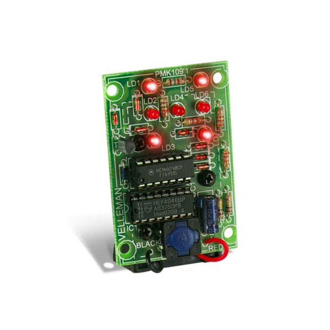
Velleman Whadda Flashing LEDs Soldering Kit
This educational soldering kit is suitable for all kinds of applications such as model making and works with a 9 V battery (not included). You can control the flashing speed with two potentiometers. Downloads Manual
€ 8,95€ 4,50
Leden identiek


