Le téléchargement intégral de ce numéro est disponible pour nos membres GOLD et GREEN sur le site Elektor Magazine !
Pas encore membre ? Cliquez ici.
stockage de l’énergieRéalisez votre propre stockage d’énergie pour réseau de panneaux photovoltaïques
simulateur de panneau solaireUne solution pour tester et optimiser les trackers MPP et les onduleurs
le concours STM32 Edge AIDécouvrez le STM32N6 et gagnez les 5000 € du concours !
Matériaux à large bande interditePourquoi y a-t-il un tel intérêt pour le SiC et le GaN ?
batterie externe pour ordinateur portableProlongez la durée de vie de votre vieil ordinateur portable
robots médicauxSurmonter les obstacles techniques et réglementaires
prévention du gel pour les vergersavec enregistrement des températures
The Analog ThingL'Arduino de l’ordinateur analogique ?
commande de relais à faible consommation d'énergieÉconomiser 90% de la puissance de commande
amélioration de la charge DC ET5410A+pour un meilleur refroidissement et moins de bruit
electronica 2024 : rétrospective
compatibilité électromagnétiqueLa CEM en quelques mots !
démarrer en électronique......Filtres actifs
réduisez les pertes des chutes de tension avec des condensateursprofitez astucieusement de la réactance capacitive
le MCP4725 : un convertisseur numérique-analogique 12 bits pas cheravec une fonction EEPROM pour un comportement sûr au démarrage
la pince de test intelligente Fnirsi LCR-ST1 pour CMS
labo de test et de mesure personnel basé sur Raspberry PiPour commencer : l'ADC
une charge électroniqueUn projet prêt à l'emploi
2025 : l'odyssée de l'IAQuelques projets pour le nouvel an
AmpVolt v2.0 : mise à jour100 A et plus !
projet 2.0Corrections, mises à jour et courrier des lecteurs
transparence éthiqueCe que révèle l’enquête réalisée par Ethics in Electronics
carte Elektor Audio DSP FX Processor (2)Création d'applications
Le téléchargement intégral de ce numéro est disponible pour nos membres GOLD et GREEN sur le site Elektor Magazine !
Pas encore membre ? Cliquez ici.
alimentation de labo à très faible bruit (1)Une source silencieuse pour les circuits sensibles
STM32 Edge AI Contest 2025 : les gagnants
les batteries aujourd’huiTechnologies et différences entre les batteries au lithium
charge électronique réglableCharge CC statique et dynamique
convertisseur abaisseur de 48 V à 5 Vune réalisation pratique
nœud de capteurs autonome v2.0Partie 2 : validation matérielle et optimisations énergétiques
varistancesDrôles de composants, la série
compteur graphique de fréquence du réseauSurveillance de la qualité du réseau
démarrer en électronique…Touche à sa fin
ferrites CMS à charge de courant de crêteplus résistantes aux pics de courant
Elektor Live! Expert Day 2025
la récupération d’énergie propulse l’IoT et l’IIoT vers une nouvelle èreLa récupération d’énergie affranchit l’IoT de la dépendance au réseau
Fnirsi DPS-150Alimentation portable compacte et convertisseur
source d’alimentation USB-C réglableTransformez votre chargeur USB-C en alimentation réglable
chargeur simple et testeur de capacitéAvec deux modules économiques « prêts à l’emploi »
détecteur de couleurs intelligent avec synthèse vocale et lecture audio basées sur l’IA
PbMonitor v2.0Présentation du système de surveillance de batteries mis à jour
un ventilateur pour la mini-plaque de refusionDes modifications astucieuses pour des résultats optimisés
sur le vifL’excès d’indulgence
projet 2.0Corrections, mises à jour et courriel des lecteurs
2026 : une odyssée de l’IAQuand les modèles commencent à orienter le matériel
picoampèremètre de précision (2)Assemblage, étalonnage et test
alimentation sans fil des appareilsavec technologie inductive
conduite autonome basée sur l’IALe Self Driving Challenge 2024 du RDW
carte son comme générateur de signauxUn PC utilisé comme émetteur de test DCF77
Le téléchargement intégral de ce numéro est disponible pour nos membres GOLD et GREEN sur le site Elektor Magazine !
Pas encore membre ? Cliquez ici.
petite caméra thermiqueréalisée avec un Arduino UNO
mise à jour du projet #3 : compteur d'énergie basé sur l'ESP32intégration et test avec Home Assistant
2024 : l'odyssée de l'IAaméliorer la détection d'objets : intégration de techniques avancées
Raspberry Pi se met à l'IAun nouveau kit comprenant un accélérateur IA matériel et un adaptateur M.2 HAT+
capteurs de stations météorologiqueslequel choisir ?
Relevé des compteurs d'eau basé sur l'IA (1)intégrez votre ancien compteur dans l'IdO !
une alarme GSMun module GSM protège votre garage à distance
optimisation et contrôle des appareils Thread à faible consommation d'énergiefaible consommation... peu d’effort ?
sur le vifmontrez-moi là où ça fait mâle
chambre à brouillard à faire soi-mêmevisualiser les rayonnements invisibles
SparkFun Thing Plus Mattercarte de développement IdO polyvalente basée sur Matter
Rétroéquipement IoTAdaptation des machines à interface RS232 à l'industrie 4.0
ajouter l’IoT grâce aux microcontrôleurs 8 bits
la technologie au service du développement durableles avancées technologiques favorisent une utilisation plus efficace de l’énergie dans de nombreuses applications
AWS pour Arduino et Cie. (1)utiliser AWS IoT ExpressLink en pratique
détecteur de flux d'air Arduinoaucun capteur externe n'est nécessaire !
détecteur de fuite d'eauconnecté à l’Arduino Cloud
le quartzdrôle de composant, la série
enregistreur universel de données de jardinageun pas vers l’Intelligence Artificielle au Jardin.
un générateur analogique 1 kHzondes sinusoïdales à faible distorsion
Miletus : utiliser les applications Web hors ligneaccès aux fonctions de l’appareil et du système
de la 4G à la 5Gest-ce une étape si facile à franchir ?
démarrer en électronique…connexions symétriques
Le téléchargement intégral de ce numéro est disponible pour nos membres GOLD et GREEN sur le site Elektor Magazine !
Pas encore membre ? Cliquez ici.
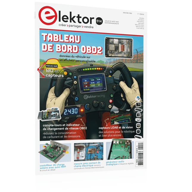
tableau de bord OBD2Des cadrans anciens aux données en temps réel
OBD2 : ajoutez un compte-tours et un indicateur de changement de vitesse à votre voitureRétro, mais extrêmement utile
capteurs de vision et LiDAR pour la robotique
Sensor+Test 2025 et PCIM 2025
mesures sans contact du champ électrique (1)Membrane vibrante pour mesurer des tensions continues ou des champs électriques statiques
détecteur de courrier sans filCapteurs optiques, radars… quelques options à explorer
Elektor Mini-WheelieUn robot auto-équilibré
cellules solairesDrôles de composants, la série
premiers pas avec un capteur radar moderneUn capteur précis qui ne passe pas inaperçu
sur le vifUsine de papier
CybersécuritéDes temps difficiles pour les hackers
Infographie : IdO et capteurs
le Bluetooth 6.0 pour des applications de télémétrie amélioréesCette nouvelle version offre des fonctions de localisation améliorées
découvrez la communication sans fil avec BeagleY-AI
Projet 2.0Corrections, mises à jour et courrier des lecteurs
démarrer en électronique……Conclusion sur les ampli-op
un puissant assistant de codage de l'IAAccélérez votre développement avec Continue et Visual Studio Code
contrôleur de charge solaire avec MPPT (2)Le circuit
détecteur d'obstacles à ultrasonsUn projet simple pour aider les malvoyants
une odyssée de l'IABilan du premier semestre
synthétiseur MIDI autonome Raspberry Pi (3)plus intelligent avec une interface utilisateur
Meshtastic : un projet de démoUn réseau intelligent de noeuds LoRa
générateur analogique de fréquences audioGénérateur de signaux sinusoïdaux de haute qualité à fréquence réglable
Le téléchargement intégral de ce numéro est disponible pour nos membres GOLD et GREEN sur le site Elektor Magazine !
Pas encore membre ? Cliquez ici.
tableau de bord OBD2Des cadrans anciens aux données en temps réel
OBD2 : ajoutez un compte-tours et un indicateur de changement de vitesse à votre voitureRétro, mais extrêmement utile
capteurs de vision et LiDAR pour la robotique
Sensor+Test 2025 et PCIM 2025
mesures sans contact du champ électrique (1)Membrane vibrante pour mesurer des tensions continues ou des champs électriques statiques
détecteur de courrier sans filCapteurs optiques, radars… quelques options à explorer
Elektor Mini-WheelieUn robot auto-équilibré
cellules solairesDrôles de composants, la série
premiers pas avec un capteur radar moderneUn capteur précis qui ne passe pas inaperçu
sur le vifUsine de papier
CybersécuritéDes temps difficiles pour les hackers
Infographie : IdO et capteurs
le Bluetooth 6.0 pour des applications de télémétrie amélioréesCette nouvelle version offre des fonctions de localisation améliorées
découvrez la communication sans fil avec BeagleY-AI
Projet 2.0Corrections, mises à jour et courrier des lecteurs
démarrer en électronique……Conclusion sur les ampli-op
un puissant assistant de codage de l'IAAccélérez votre développement avec Continue et Visual Studio Code
contrôleur de charge solaire avec MPPT (2)Le circuit
détecteur d'obstacles à ultrasonsUn projet simple pour aider les malvoyants
une odyssée de l'IABilan du premier semestre
synthétiseur MIDI autonome Raspberry Pi (3)plus intelligent avec une interface utilisateur
Meshtastic : un projet de démoUn réseau intelligent de noeuds LoRa
générateur analogique de fréquences audioGénérateur de signaux sinusoïdaux de haute qualité à fréquence réglable
ELEKTOR AIDE L'électronique dans des temps difficiles
AFFICHAGE D'INFORMATION POUR LA MAISON avec Windows sur le Raspberry Pi
DÉMARRER AVEC NODE-RED un outil de programmation open source basé sur des blocs visuels
LA tombola d'ÉTÉ d'ELEKTOR
GREATSCOTT ! CONSTRUIRE UN SYSTÈME D'ALARME LORA
REVUE : ALIMENTATION DE LABORATOIRE JOY-IT RD6006 (KIT)
REVUE : INTERFACEBOARD GREATFET ONE
QUI N'HONNE PAS LES PETITS – XXL de la boîte à suggestions d'Elektor
ANTENNE WIFI EXTERNE 2,4 GHZ POORLUIS
CONTRÔLE FACILE DE LA TEMPÉRATURE MARCHE/ARRÊT AVEC CHAPEAU RASPBERRY PI
COMMENT PRENDRE DE (BONNES) PHOTOS DÈS L'IMPRESSION... ...et les composants électroniques ?
REVUE : NOYAU I2CDRIVER
ÉCRAN TACTILE JOY-VIEW 13 DE JOY-IT
BOOSTER LED POUR MICROCONTRÔLEURS avec un seul composant !
MACHINE À LAVER À ULTRASONS EXPÉRIMENTALE
REVUE : GÉNÉRATEUR DE SIGNAUX JOY-IT JDS2915 générateur de signaux doubles avec compteur de fréquence dans un boîtier métallique
PROGRAMMATION DES FEUX DE SIGNALISATION EN LANGAGE PIC ASSEMBLY
LED CLIGNOTANT PERMANENT
CAPTEUR DE HALL EXPÉRIMENTAL
DÉTECTER LES COURT-CIRCUITS AVEC UN MILLIOHM OU ESR MÈTRE
KIT PRATIQUE ÉLECTRIQUE SDR
PIPELINE DE LABORATOIRES ÉLECTRIQUES
KICK-STARTER ÉLECTRIQUE ....eh bien, vous voyez ce que nous voulons dire.
AVEZ-VOUS VRAIMENT BESOIN DE TOUT ÇA ??? ici, je passe de nombreuses heures sur des projets électroniques...
LABORATOIRE EST OUEST MEILLEUR un aperçu du plus saint des saints, où naissent des projets intéressants
BONJOUR LE MONDE! NOUS SOMMES ELEKTOR ET NOUS SOMMES SOCIAUX
M4 + A7 + GPU : UNE ÉQUIPE DE RÊVE INÉGALE le nouveau SoC STM32MP1 pour les travaux plus lourds
CONFIGURATION DE TEST POUR LE 16F18877 ET AUTRES GRANDES PHOTOS
COMMUNICATION INTER-ΜC AVEC LE BUS SPI ET ATMEGA328P
SIX VARIANTES DE L'OSCILLATEUR LF/AF (et la capacité de M. Miller)
BBC MICRO:BIT oscilloscope absolument minimaliste avec affichage LED
FEU DE RUNNING À LED 'KNIGHT RIDER' AVEC ESP32
GÉNÉRATEUR DE SIGNAUX AM LW/MW AVEC ATTINY13
DIPMÈTRE ABSOLUMENT MINIMALISTE
SCOOTERS ÉLECTRIQUES BON MARCHÉ quelle est la qualité d'un scooter électrique « homologué » à 300 euros de Lidl ?
AIDE AU STATIONNEMENT À ULTRASONS AVEC ARDUINO UNO
PÉDALE DE DISTORSION AVEC AMPLI OP ET TUBES DE CHARGE SPATIALE
INDISPENSABLE POUR CHAQUE LABORATOIRE D'ÉLECTRONIQUE
HEXADOKU
IA POUR DÉBUTANTS (2) réseaux de neurones avec Linux et Python
LORA MET DE RASPBERRY PI PICOpret met MicroPython
WAT IS RISC-V?en waarom de industrie zo enthousiast is over een nieuwe processorkern!
ELEKTOR @ 60de Halfgeleidergidsen
VEELZIJDIGE VOEDING VOOR BREADBOARDSplus en min uit 5 V van USB
RASPBERRY PI PICO ESSENTIALSvoorbeeldhoofdstuk: WiFi met de Raspberry Pi Pico
MAGNETISCHE LEVITATIE “THE EASY WAY”
KENNISMAKING MET DE PARALLAX PROPELLER 2 (DEEL 3)smart pins en seriële data (UART)
NUCLEO-BOARDS PROGRAMMEREN MET DE STM32CUBEIDEvoorbeeldhoofdstuk: FreeRTOS voor de STM32-MCU
UITBREIDING VAN DE MT3608 DC-DC STEP-UP CONVERTERMODULE
MINIWARE DT71 DIGITAL TWEEZERS
WEARABLE WIFI-GADGETESPHome, uw steun en toeverlaat
ALLE BEGIN......sluit het onderwerp “condensatoren” hiermee af
EENVOUDIGE SKETCHES MET BEHULP VAN HET QWIIC-ECOSYSTEEM
JAVA OP DE RASPBERRY PIdeel 2: GPIO’s besturen met een REST-service van Spring
RASPBERRY PI COMPUTE MODULE 4een Raspberry Pi voor de industrie
DRAAGBAAR STAND-ALONE LUCHTKWALITEIT-DISPLAY VOOR 2,5MM-DEELTJEShoud(t) een oog op uw gezondheid
UIT HET LEVEN GEGREPENvroeger was de toekomst beter
MICROPYTHON VOOR DE ESP32 EN CONSORTENdeel 1: installatie en onze eerste programma’s
CHARGE COUPLED DEVICES IN OSCILLOSCOPENvreemde onderdelen
ESD – DE ONZICHTBARE VIJANDbliksem bij heldere hemel vernielt componenten
ZONNE-ENERGIE VOOR MAAIROBOTSecologisch, goedkoop, eenvoudig!
EUROPA’S INSPANNINGEN OM BIG TECH TE TEMMEN
HEXADOKUThe Original Elektorized Sudoku
Testeur audio pas cher avec un logiciel basé sur PC et une interface audio USB
Fréquencemètre de courant alternatif surveille la fréquence et la tension du secteur
Un petit compteur à induction solution abordable pour l'établi
Flottant sur les ondes sonores un examen plus approfondi du kit de lévitation acoustique Makerfabs
Tous les débuts... ...va rectifier
FFWD : j’ai encore hâte !
Premiers pas avec votre oscilloscope voici comment utiliser les boutons et les interrupteurs
Un MSF-SDR avec le Raspberry Pi Pico décoder le signal horaire avec un Pi Pico-SDR
Capteurs d'humidité du sol pour systèmes d'irrigation arrosage automatique
Troubles sur le marché des équipements de test et de mesure les petits acteurs innovent
Infographie Elektor
L'inspiration, c'est de ça qu'il s'agit Entretien avec l'entrepreneur Walter Arkesteijn, InnoFaith Beauty Sciences
Minimiser les interférences CEM des bobines de stockage
Création d'interfaces graphiques avec Python : Morpion
Jeroen et Jan continuent d'être pionniers
Compteur ESR analogique simple avec précision de compteur à bobine mobile
Feu tricolore Sigfox CO2 sans réseau WiFi !
Les femmes dans la technologie « Tout est une question de mérite jusqu'à ce que le mérite ait des seins »
Oscilloscope pour tablette à petit budget ADS1013D rapport qualité/prix ?
Anatomie des prises intelligentes Lesquels sont adaptés aux hackers ?
Impédance cutanée et capacité cutanée étudié expérimentalement
Tiré de la vie Rien de bon dans notre propre pays
J'ai consulté le Pokit Meter un couteau suisse parmi les instruments de mesure
Hexadoku Des puzzles pour les ingénieurs en électronique
Elektor GREEN en GOLD leden kunnen deze uitgave hier downloaden.Nog geen lid? Klik hier om een lidmaatschap af te sluiten.
Kiesschijftelefoon als afstandsbedieningvoor licht kies 1; voor koffie kies 2
GPS-gebaseerde snelheidsmeternooit meer bekeuringen
RGB-stroboscoop met Arduinokleurige toepassing van een nuttig instrument
Draadloze nooddrukknopmeer veiligheid met LoRa
Alle begin......volgt de emitter
Vrij te kiezen onafhankelijke hystereseniveaus voor comparatorenmet simulaties, spreadsheets en algebra
Impedantie-analyzer op basis van een ESP32simpel, weinig onderdelen en goedkoop!
Oost West Lab Bestzelfbouw moet gestimuleerd!
Het MCCAB Arduino Nano Training Boardalle hardware voor de “Microcontrollers Hands-On Course”
Uit het leven gegrepenmodern luddisme
Sensor-ABC: de DS18B20 temperatuursensoraansluiting op de 1-Wire bus
Gaan Matter en Thread het Smart Home redden?nieuwe standaarden om het slimme huis te vereenvoudigen
Een kwestie van samenwerkingontwikkelen met het Thing Plus Matter Board en Simplicity Studio
Elektor IIIIinfographicIoT en sensoren
Matter, ExpressLink, Rainmaker – waar hebben we het over?vraaggesprek met Amey Inamdar van Espressif
De juiste keuze van microcontroller-ontwikkelkitsvoor IoT- en IIoT-toepassingen
Condensatoren gedragen zich niet altijd capacitief!
Een NTP-klok met CircuitPythonwaarom zou je deze programmeertaal gebruiken?
Bouw een cool IoT-display'met de Phambili Newt
De doppler-bewegingssensor HB100theorie en praktijk
Een gids voor puristisch programmeren (deel 1)voor STM32 en andere controllers
Siglent SDM3045X-multimeter
Microprocessoren voor embedded systemenvreemde onderdelen
Microcontroller-documentatie verklaarddeel 3: blokschema’s en meer
Low-power LoRa-weerstationbouw zelf een weerstation met een groot bereik
Transverter voor de 70cm-band
Klimaat aan ingenieurssnelheid is geboden!
Hexadoku
Elektor GREEN en GOLD leden kunnen deze uitgave hier downloaden.
Nog geen lid? Klik hier om een lidmaatschap af te sluiten.
Kleine warmtebeeldcameraeen op Arduino UNO gebaseerde DHZ-oplossing
Project-update #3: ESP32-gebaseerde energiemeterintegratie en test met Home Assistant
2024: een AI-odysseeobjectdetectie verbeteren met verfijnde technieken
De Raspberry Pi gaat AInieuwe kit bevat M.2 HAT+ met AI-versneller
Sensoren voor weerstationswat is de beste keuze?
Lees uw analoge watermeter uit met AI (1)koppel uw oude watermeter met het IoT!
GSM-alarmdraadloze garagebeveiliging
Low-power Thread-devices geoptimaliseerd en onder de loep genomenweinig vermogen... weinig inspanning?
Uit het leven gegrepende genderkloof
Zelfbouw-nevelkamermaak onzichtbare straling zichtbaar
SparkFun Thing Plus Mattereen veelzijdig Matter-gebaseerd IoT development board
IoT-retrofittenRS232-apparaten klaarstomen voor Industry 4.0
Stimuleer het IoT met 8-bit MCU’s
Technologie stimuleert duurzaamheidvooruitgang leidt in veel toepassingen tot efficiënter energiegebruik
AWS voor Arduino en co. (1)AWS IoT ExpressLink in de praktijk
Luchtstroomdetector met alleen een Arduinozonder externe sensoren!
Lekdetectorverbonden met de Arduino-cloud
Kristallenvreemde onderdelen
Universele logger voor de tuinAI-tuinieren komt een stapje dichterbij
Analoge 1kHz-generatorsinussen met geringe vervorming
Miletus: webapps offline gebruikeninclusief toegang tot het systeem en het apparaat!
Van 4G naar 5Gis het echt zo eenvoudig?
Alle begin......gaat symmetrisch
Elektor GREEN en GOLD leden kunnen deze uitgave hier downloaden.
Nog geen lid? Klik hier om een lidmaatschap af te sluiten.
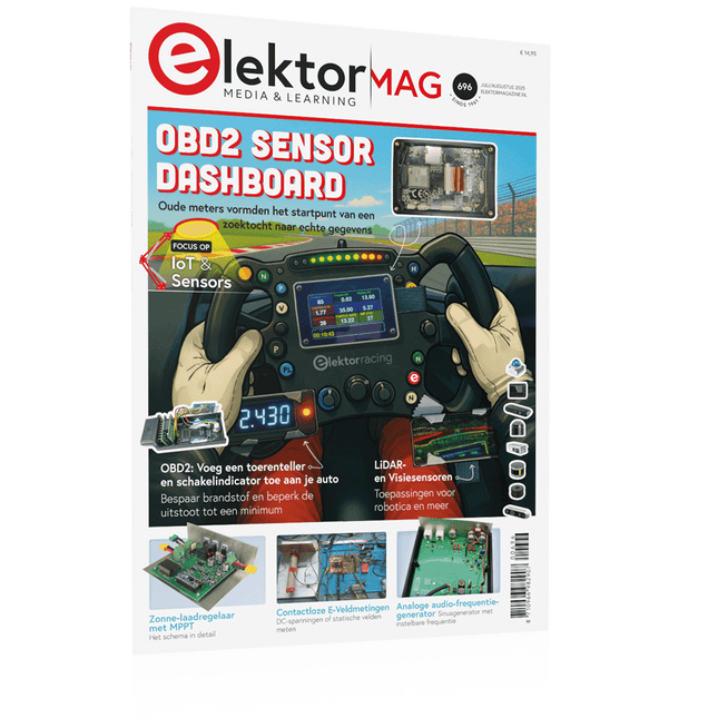
OBD2-sensordashboardOude meters vormden het startpunt van een zoektocht naar echte gegevens
OBD2: voeg een toerenteller en schakelindicator toe aan je autoRetro, maar uiterst nuttig
LiDAR- en Visiesensoren voor Robotica
Sensor+Test 2025 en PCIM 2025
Contactloze E-Veldmetingen (1)Een Trillende Membraan voor het Detecteren van Gelijkspanningen of Statische Elektrische Velden
Draadloze brievenbusmeldervan optische sensoren tot radar: enkele mogelijkheden
Elektor Mini-Wheelieeen zelfbalancerende robot
ZonnecellenVreemde onderdelen, de serie
Aan de slag met een moderne radarsensorStaat een nauwkeurige meting op uw radar?
Uit het leven gegrepenpapierfabriek
CybersecurityZware tijden voor hackers
Infographics: IoT en sensoren 2025
Bluetooth 6.0 brengt verbeterde toepassingen voor afstandsbepalingNieuwe versie biedt betere apparaatpositionerings- en -locatieservices
Draadloze communicatie verkennen met BeagleY-AI
Err-lectronicsCorrecties, updates en lezerspost
Alle begin......sluit het thema opamps af
Een krachtige AI-codeerassistentsneller ontwikkelen met Continue en Visual Studio Code
Zonne-laadregelaar met MPPT (2)Het schema
Ultrasone obstakeldetectoreen eenvoudig project om slechtzienden te helpen
2025: Een AI-odysseeHalfjaaroverzicht
Raspberry Pi Standalone MIDI-synthesizer (3)Het slimmer maken en een gebruikersinterface toevoegen
Meshtastic: een demonstratieprojectEen slim netwerk van LoRa-radio's
Analoge audio-frequentiegeneratorHoogwaardige sinusgenerator met instelbare frequentie
Elektor GREEN en GOLD leden kunnen deze uitgave hier downloaden.
Nog geen lid? Klik hier om een lidmaatschap af te sluiten.
OBD2-sensordashboardOude meters vormden het startpunt van een zoektocht naar echte gegevens
OBD2: voeg een toerenteller en schakelindicator toe aan je autoRetro, maar uiterst nuttig
LiDAR- en Visiesensoren voor Robotica
Sensor+Test 2025 en PCIM 2025
Contactloze E-Veldmetingen (1)Een Trillende Membraan voor het Detecteren van Gelijkspanningen of Statische Elektrische Velden
Draadloze brievenbusmeldervan optische sensoren tot radar: enkele mogelijkheden
Elektor Mini-Wheelieeen zelfbalancerende robot
ZonnecellenVreemde onderdelen, de serie
Aan de slag met een moderne radarsensorStaat een nauwkeurige meting op uw radar?
Uit het leven gegrepenpapierfabriek
CybersecurityZware tijden voor hackers
Infographics: IoT en sensoren 2025
Bluetooth 6.0 brengt verbeterde toepassingen voor afstandsbepalingNieuwe versie biedt betere apparaatpositionerings- en -locatieservices
Draadloze communicatie verkennen met BeagleY-AI
Err-lectronicsCorrecties, updates en lezerspost
Alle begin......sluit het thema opamps af
Een krachtige AI-codeerassistentsneller ontwikkelen met Continue en Visual Studio Code
Zonne-laadregelaar met MPPT (2)Het schema
Ultrasone obstakeldetectoreen eenvoudig project om slechtzienden te helpen
2025: Een AI-odysseeHalfjaaroverzicht
Raspberry Pi Standalone MIDI-synthesizer (3)Het slimmer maken en een gebruikersinterface toevoegen
Meshtastic: een demonstratieprojectEen slim netwerk van LoRa-radio's
Analoge audio-frequentiegeneratorHoogwaardige sinusgenerator met instelbare frequentie
De Elektor Laserkop transformeert de Elektor Sand Clock in een klok die de tijd op glow-in-the-dark-film schrijft in plaats van op zand. Naast het weergeven van de tijd kan het ook worden gebruikt om kortstondige tekeningen te maken. De 5 mW laserpointer, met een golflengte van 405 nm, produceert heldergroene tekeningen op de glow-in-the-dark-film. Voor het beste resultaat gebruikt u de kit in een slecht verlichte kamer. Waarschuwing: Kijk nooit rechtstreeks in de laserstraal!
De kit bevat alle benodigde componenten, maar het solderen van drie draden is vereist.
Opmerking: Deze kit is ook compatibel met de originele Arduino-gebaseerde Zandklok uit 2017. Voor meer details, zie Elektor 1-2/2017 en Elektor 1-2/2018.
De Elektor LoRa Nodeveelzijdige 868MHz-afstandsbediening met status-feedback, een groot bereik en een STM32
Interactiefcorrecties & updates || vragen & antwoorden
Analoge elektronica ontwerpencase-study #1 – deel 2: de voorversterker voor de MEMS-microfoon
My IoT-button: de knop voor het netdeel 1: IoT-architectuur
BASIC voor ESP32/ESP8266programmeren met Annex WiFi RDS
ESP32-deurbel via Telegram“de postbode belt maar één keer”
Wie het kleine niet eert
Beginnen met LoRaWANmet Blue Pill, LoRa-breakout-board en The Things Network
“Een voorvechter van Open Internet”vraaggesprek met Wienke Giezeman, initiatiefnemer van The Things Network
Meadow F7een board voor .NET-ontwikkelaars
Multitasking met de ESP32 (2)taakprioriteiten
Met de vos in het IoT (3)eerste stappen op het net
Raspberry Pi Bash-commando cheat sheet
De meest succesvolle start-up aanjager?HighTechXL, Eindhoven, Nederland
Review: RPi-HAT Enviro+meet milieudata met Raspberry Pi en de Enviro+ HAT
Uit het leven gegrepenonderdelen bestellen in Oekraïne en Rusland
Review: Andonstar AD407beter dan zijn voorganger?
Oost West Lab Besteen blik in het allerheiligste, waar onbevoegden geen toegang hebben...
Optische probe voor de oscilloscoopmeet helderheidsvariaties van verlichtingssystemen
Het TABULA-project: een updatetangibles met gebruikersfeedback
Hoe... de maximale kortsluitstroom berekenenen de juiste zekeringautomaat te kiezen
TMS1000-serie microcontrollersvreemde onderdelen
Alle begin......hoeft niet zo moeilijk te zijn
Developer’s Zonetips & trucs, vakkunstigheden en andere nuttige informatie
Leidingen opsporenover het zoeken en vinden van onzichtbare en onderbroken leidingen
Review: Joy-IT DMSO2D72 portable 3-in-1 oscilloscoop
Doe-het-zelf PC voor het elektronicalabtips voor componentenkeuze en bouw
De Elektuur 'Intelekt' schaakcomputer (1981)Tiny Chess-86 geport naar de Intel 8088
PCB-kunstverlegt de grenzen van industriële productie
Hexadoku
BEAUCOUP D'AMOUR D'INGÉNIERIE DE L'UE ET DES ÉTATS-UNIS
SPARKFUN : LA VISION D'UN INGÉNIEUR
DÉMARRER AVEC MICROMOD
UNE MISE À NIVEAU POUR VOTRE JETBOT SPARKFUN comment j'ai étendu les fonctionnalités de mon JetBot (avec le Jetson Nano de NVIDIA).
PROGRAMMER UN FPGA
CONSTRUISEZ VOTRE PROPRE STATION DE RÉFÉRENCE GNSS
LE PROJET HORLOGE
SOUS LE CAPOT : KIT DE L'INVENTEUR SPARKFUN
GLENN SAMALA DE SPARKFUN SUR LE DÉVELOPPEMENT DE PRODUITS ET LES NOUVEAUX MARCHÉS
IMPRIMEZ LE VÔTRE AVEC SPARKFUN À LA CARTE
CONCEVOIR AVEC LE SPARKFUN ARTEMIS
PROTOTYPAGE RAPIDE AVEC L'ÉCOSYSTÈME QWIIC
AFFICHE - QWIIC
SOUS LE CAPOT : LE KIT SUPERCHARGEUR LIPO GREATSCOTT!/ELEKTOR DIY
UNE ÉLECTRONIQUE REMARQUABLE du passé de SparkFun
PARKING PARFAIT AVEC LIDAR
RÉPARATION D'UN 'COUSSIN ENTERRÉ'
DE LA CONCEPTION AU PRODUIT : LE SPARKFUN RTK SURVEYOR
BONJOUR LE MONDE DU RASPBERRY PI PICO ET RP2040 le premier microcontrôleur et puce Raspberry Pi
ROBOTS À QUATRE PATTES POUR AUTO-CONSTRUCTION
AFFICHE - MICROMOD
DÉVELOPPEMENT RISC-V IOT DANS AWS AVEC LES BIBLIOTHÈQUES FREERTOS
OUI, ÉLECTRONIQUE = FUN ! passionnés d'électronique entre eux
CATALOGUE DE PRODUITS SPARKFUN
HEXADOKU Le Sudoku électorisé original
Bouw uw eigen RISC-V-controllerEerste stappen met de NEORV32 RISC-V softcore voor goedkope FPGA’s
Het gebruik van Arduino’s seriële plotterGrafieken plotten met Arduino is gemakkelijk
CLUE van AdafruitEen slimme oplossing voor IoT-projecten
Bufferboard voor de Raspberry Pi 400Bescherm uw I/O’s
Raspberry Pi RP2040-boards in overvloed
Een handboek voor DHZ elektronische beveiliging en spionageSRAM – gebakken of diepgevroren
Onderdelen identificerenTips & trucs, vakkunstigheden en andere nuttige informatie
DHZ aanraakloze lichtschakelaar
Alle begin......gaat compenseren en transformeren
Nieuwe embedded-ontwikkelingenRust en het up-to-date houden van IoT-implementaties
Infographics
Hoe de industrie- en automobielsector zullen profiteren van 5G
Relais met bewegende spoelVreemde onderdelen
Oost West Lab BestAlles draait om de bank...
Kennismaking met neuronen in neurale netwerkenDeel 4: embedded neuronen
Magnetische levitatie “the very easy way”De derde en meest compacte versie
PLC-programmering met de Raspberry Pi en het OpenPLC-projectVisualisatie van PLC-programma’s met AdvancedHMI
Uit het leven gegrepenInpakken en wegwezen
Onder de radarMicrocontrollers die u zou moeten kennen
Draadloos monitoren en debuggenvoor Arduino, ESP32 en co.
Draagbare temperatuur- en vochtigheidsmetermet gebruiksklare modules
Lithium-accupacks reparerenSpaart geld + geeft meer kracht!
GUI's maken met PythonMeme-Generator
De drie grote vraagtekensWaarom wat wie
Hexadoku
Elektor GREEN en GOLD leden kunnen deze uitgave hier downloaden.Nog geen lid? Klik hier om een lidmaatschap af te sluiten.
Cloc 2.0de wekker die je altijd al wilde hebben
PIO in de praktijkexperimenten met de programmeerbare I/O van de RP2040
Armeluis chiptweakerwe krijgen je wel (goedkoop) aan de praat...
Echte USB-toevalsgeneratortwee PIC’s voor de prijs van één AVR
Pimp my mike...opvoeren doe je zelf
FFT met Maixduinofrequentiespectra vastleggen
Uit het leven gegrepenontwerp(on)logica
UCN5804 stappenmotordrivervreemde onderdelen
Simuleren met Micro-Capeerste stappen in een complexe wereld
PAUL Award 2022jonge technische talenten en hun creatieve ontwerpen
Mijn eerste Software Defined Radioin minder dan 15 minuten klaar
Microcontroller-documentatie verklaarddeel 1: de opzet van een datasheet
Hoe verder met AI en embedded systems?tools, platforms – en worden schrijvers obsoleet?
Digitalisering van verticale landbouw
Elektor Infographicsembedded en AI vandaag – en morgen
Een introductie tot TinyML
Casestudy KwickPOS
High-performance in elke klassecomputer-on-module standaarden
Alle begin......wordt eindelijk actief!
I²C-communicatie met Node.js en een Raspberry Pibekijk sensordata in een browser
Video-output met microcontrollers (2)VGA en DVI
Het Metronom real-time besturingssysteemeen RTOS voor AVR-processoren
DVI op de RP2040vraaggesprek met Luke Wren, chipontwikkelaar bij Raspberry Pi
Display-HAT Minitoont het weer op de Raspberry Pi
De WEEF 2022 Awardshet goede vieren
Hexadoku
Elektor GREEN en GOLD leden kunnen deze uitgave hier downloaden.
Nog geen lid? Klik hier om een lidmaatschap af te sluiten.
CaptureCountobjectdetector en -teller op de Raspberry Pi 5
Spanningsreferentie met Arduino Pro Minilineariseer en kalibreer analoge ingangen
FPGA’s voor beginnersvan MCU naar FPGA-programmering
Update: STM32 Wireless Innovation Design Contest 2024
Bluetooth LE met MAUIbesturingsapps voor Android en co.
Port Expander breakout-boardmeer I/O’s op je development board
AI-specialistmachine learning met de Jetson Nano
2024: een AI-odysseeeen eerste verkenning van TensorFlow
262.144 manieren om Game of Life te spelenlezersproject in het kort
Uit het leven gegrepende Chinese draak
Draaien met die (DC-borstel)motor!voorbeeldprojecten uit de Elektor Motor Control Development Bundle
ESP32/RS-232-adapterdraadloze verbinding voor klassieke meetinstrumenten
Alle begin......gaat verder met de opamp
Aanbevolen ESP-bibliotheken
Piëzo-elektrische componentenvreemde onderdelen
Slimme objecttellereenvoudige beeldherkenning met Edge Impulse
Oplossingen voor de lastigste uitdagingen bij embedded ontwikkeling
ESP32 Terminalhandheld met aanraakscherm
Aan de slag met Zephyr RTOSkrachtig – maar lastig...
Bekroonde ethiekeen vraaggesprek met Alexander Gerfer, CTO van Würth Elektronik eiSos, over het faciliteren van innovatie en bewust gedrag
Project 2.0correcties, updates en brieven van lezers
Elektor GREEN en GOLD leden kunnen deze uitgave hier downloaden.
Nog geen lid? Klik hier om een lidmaatschap af te sluiten.
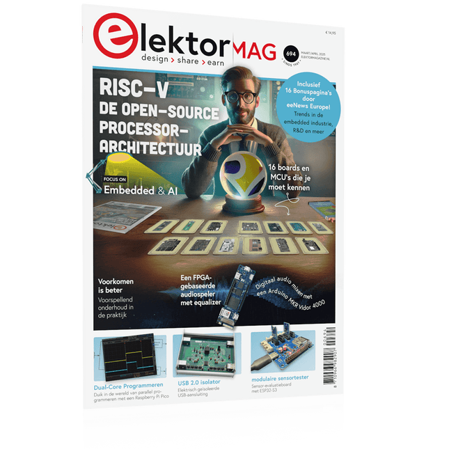
De open-source processorarchitectuur RISC-V16 boards en MCU's die je moet kennen
Een FPGA-gebaseerde audiospeler met equalizer (1)Digitaal audio mixen met een Arduino MKR Vidor 4000
Laserkop voor pico-gebaseerde zandklokTekenen met licht
Doe mee aan de STM32 Edge AI Contest
Een multi-sensor plantenmonitor-systeemdraadloze meting van watertoevoer en lichtomstandigheden
Maixduino AI-gestuurde automatische portiergezichtsdetectie met een camera
Embedded Electronics 2024AI gaat de industrie opnieuw vormgeven
Lading-gebaseerde in-Memory computing bij EnCharge AI
AI-Inferentie met 10 Keer Lager Energieverbruik en 20 Keer Lagere Kosten
Click board ondersteunt het ontwikkelen en trainen van ML-modellen voor trillingsanalyse
De Elektor Mini-WheelieEen kit voor een zelfbalancerende robot
MCU, ik zie jeMCUViewer: open-source multiplatform debugging-tool
USB 2.0-isolatorelektrisch geïsoleerde USB-aansluiting
Voorkomen is betervoorspellend onderhoud in de praktijk
SPoE – Elektromagnetische compatibiliteitSingle pair met Power-over-Ethernet door de ogen van EMC
Retro techEen nieuwe wereld met kleurentelevisie
ECG-monitorimplementatie met Hexabitz-modules en een STM32CubeMonitor
De strijd om AI aan de edge
Met HaLow Wi-Fi is een record afstand bereikt van 16 km op 900 MHz
Eerste CHERI RISC-V Embedded Chip en Early Access programma
Derde generatie bosbranddetectie maakt gebruik van satellietverbindingen
Uit het leven gegrepenkeuzestress
Alle begin......filtert verder en regelt tonen
Quasi-analoog uurwerkwedergeboorte van een Elektor-klassieker
Een modulaire sensortesterSensor-evaluatieboard met ESP32-S3
2025: Een AI-OdysseeDe opkomst van foundation modellen en hun rol in het democratiseren van AI
Raspberry Pi standalone MIDI-synthesizer (1)voorbereiding van een platform voor enkele edge-AI-experimenten
Err-lectronicsCorrecties, updates en brieven van lezers
Universele AI RISC-V processor doet ze allemaal - CPU, GPU, DSP, FPGA
Interview met de CEO: Ventiva's dunne en coole technologie
Dual-core programmeren met een Raspberry Pi Picoduik in de wereld van parallel programmeren
Elektor GREEN en GOLD leden kunnen deze uitgave hier downloaden.
Nog geen lid? Klik hier om een lidmaatschap af te sluiten.
PIO programmeren op de Raspberry Pi PicoNegen instructies, veel mogelijkheden
AI buiten de browser brengenAI-CLI's gebruiken voor het coderen, compileren en valideren van embedded projecten
De Scrutiny DebuggerDebuggen, visualiseren en testen van code in Embedded C/C++
Sigfox breakout board (1)Een zelfgebouwde radio BoB
Low-Noise voeding (2)Constructie, montage en praktische implementatie
Eenvoudige signaalgenerator met de RP2040Analoge en digitale signalen voor ongeveer €10
De toekomst van slimme huizen verkennen met Matter en Edge AIBieden de nieuwste updates van Matter en de opkomst van Edge AI technici eindelijk de tools om de intelligente, slimme huizen te bouwen die gebruikers zijn beloofd?
Differentiële druksensorenVoorspellend onderhoud in HVAC-systemen
Security by designTechnische basisprincipes beperken storingen
Embedded security is niet langer optioneel
CRA en PQC herzien prioriteiten voor embedded securityWaarom zelfs kleine IoT- en industriële bedrijven een upgradeplan nodig hebben
embedded world 2026Een interview met Benedikt Weyerer, Executive Director embedded world
Praktijkervaring met I3CGebruik van hardware van ST en Microchip
Het BLEnky-projectSnelle prototyping voor Bluetooth Low Energy toepassingen
Pulsbreedtemodulatievan een eenvoudige aan/uit-thermostaat naar een rimpelloos DC-signaal
AudiotronicaOorstrelende elektronica voor zelfbouw
Uit het leven gegrepenRead the f...ing manual!
ESP32 audio transceiver board (Deel 4)Afstemmen van de kloksignalen en een bekabelde versie
2026: An AI OdysseyDe kater van Vibe-Coding in 2025
Symmetrische DC-belastingStatische of dynamische en symmetrische gelijkstroombelasting
Gezichten tellen met MaixCAMEen eenvoudige methode om de omvang van het publiek vast te leggen