This PCIe to M.2 adapter is specifically designed for the Raspberry Pi 5. It supports the NVMe protocol for M.2 SSDs, enabling fast read and write operations, and adheres to the HAT+ standard. The adapter is compatible with M.2 SSDs in the 2230 and 2242 sizes.
Inbegrepen
1x PCIe to M.2 HAT+ Adapter
1x 2x20 Pin header
1x 16P cable (40 mm)
1x Standoff pack
Downloads
Wiki
De Waveshare PoE M.2 HAT+ (B) combineert Power over Ethernet (PoE) en PCIe-naar-M.2-functionaliteit voor de Raspberry Pi 5. Hij ondersteunt de IEEE 802.3af/at-netwerkstandaarden en is geschikt voor M.2 NVMe SSD's in de formaten 2230, 2242, 2260 en 2280. Bovendien maakt hij SSD-boot mogelijk voor de Raspberry Pi.
Kenmerken
Standaard Raspberry Pi 40-pins GPIO-uitbreidingsheader, compatibel met Raspberry Pi 5
Ondersteunt Power over Ethernet (PoE) en voldoet aan de IEEE 802.3af/at-netwerkstandaarden
Maakt gebruik van een volledig geïsoleerde Switch Mode Power Supply (SMPS) voor stabiele stroomvoorziening
Ondersteunt harde schijven met NVMe-protocol M.2-interface, voor hoge lees-/schrijfsnelheden en een hoge efficiëntie
Biedt 1x PCIe in Gen2- of Gen3-modus
Speciaal ontworpen voor de Raspberry Pi 5
Compatibel met M.2 SSD's in de formaten 2230, 2242, 2260 en 2280
Specificaties
PoE-voedingsingang
37~57 V DC
Uitgangsvermogen
GPIO-header: 5 V/4,5 A (max.)2P-header: 12 V/2 A (max.)
Netwerkstandaard
IEEE 802.3af/at PoE
Afmetingen
56 x 85 mm
Inbegrepen
1x Waveshare PoE M.2 HAT+ (B)
1x 16-pins PCIe-kabel
1x SSD-montageschroef
1x Schroevenset
Downloads
Wiki
The PicoGo is a smart mobile robot based on Raspberry Pi Pico, it includes ultrasonic module, LCD module, Bluetooth module, line following module, and obstacle avoidance module, all these functions are highly integrated for easily achieving IR obstacle avoidance, auto line following, Bluetooth/IR remote control, and more. With various advanced features, it will help you fast get started with smart robot design and development. Features Standard Raspberry Pi Pico header, supports Raspberry Pi Pico series Battery protection circuit: over charge/discharge protection, over current protection, short circuit protection, reverse proof, more stable and safe operating Recharge/Discharge circuit, allows programming/debugging concurrently while recharging 5-ch infrared sensor, analog output, combined with PID algorithm, stable line tracking Onboard multiple smart robot sensors like line tracking, obstacle avoidance, no more messy wiring 1.14-inch IPS colorful LCD display, 240 x135 pixels, 65K colors Integrates Bluetooth module, allows teleoperations like robot movement, RGB LED display color, buzzer, etc. by using mobile phone APP N20 micro gearmotors, with metal gears, low noise, high accuracy Colorful RGB LED IR obstacle avoidance The module sends IR beam and detects objects by receiving the reflected IR beam, to easily avoid obstacles in the way. Auto line following Features 5-ch IR detector for sensing and analysing the black line, combined with PID algorithm for adjusting robot movement, high sensitivity, stable tracking. Ultrasonic sensor Ultrasonic is generally faster and easy-to-calculate, suitable for functions like real time control, and obstacle avoidance, with the industrial practical ranging accuracy, it is widely used on robot research and development. Object tracking The robot is able to detect front object by ultrasonic or IR, and keeps moving to track the target automatically. IR remote control Integrates IR receiver, so that you can control the robot to move or turn direction by sending infrared light from the remote controller. Bluetooth remote control Comes with mobile phone APP, allows you to use the phone to control the movement of the robot, or control its peripherals like changing LED color, making the buzzer to sound, etc. RGB LED control Included 1x PicoGo base board 1x PicoGo acrylic panel 1x 1.14-inch LCD Module 1x Ultrasonic sensor x1 1x IR remote controller 1x USB-A to micro-B cable 1.2 m 1x PH2.0 8-Pin cable 5 cm opposite side headers 1x Mini cross wrench sleeve 1x Screwdriver 1x Screws and standoffs pack Required 1x Raspberry Pi Pico (pre-soldered header) 1x 5 V/3 A power supply 2x 14500 batteries Downloads Wiki
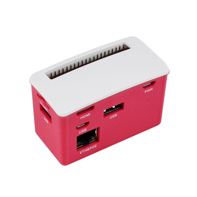
The PoE-ETH-USB-Hub-Box is a Hub kit with PoE/ETH/USB Hub HAT inside. It is tailored for Raspberry Pi Zero series, small in size, each cut-out of the case is exactly aligned with the connector. The case adopts classic Raspberry Pi red/white color combination, with quality dull polish surface, effectively keeping the Zero away from dust. By using this small Hub Box and some proper 802.3af-compliant power sourcing equipments, it is possible to provide both network connection and power supply for your Raspberry Pi Zero in only one Ethernet cable, along with 3x extended USB ports.
Kenmerken
Designed for Raspberry Pi Zero, compatible with Zero series boards
Incorporates RTL8152B Ethernet chip, with 10M / 100M auto-negotiation RJ45 port
PoE (Power over Ethernet) feature, 802.3af-compliant
Fully isolated SMPS (Switch Mode Power Supply)
3x extended USB ports, compatible with USB 2.0 / 1.1
Angle rounded design, smooth hand feeling, 'simple snap' case lid
Quality ABS material, dull polish surface, anti-fingerprint
Comes with two different lids, changing as you like
Inbegrepen
1x PoE/ETH/USB Hub HAT kit
1x ABS case
4x Rubber feets
1x Screws pack
Downloads
Documentation
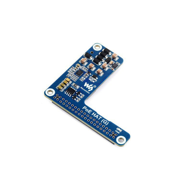
De PoE HAT (G) is een IEEE 802.3af/at-compatibele PoE (Power Over Ethernet) HAT voor Raspberry Pi 5. Door gebruik te maken van een PoE-router of switch die de IEEE 802.3af/at-netwerkstandaard ondersteunt, is het mogelijk om zowel de netwerkverbinding als de voeding voor uw Raspberry Pi te verzorgen in slechts één Ethernet-kabel.
Kenmerken
Standaard Raspberry Pi 40-pins GPIO-header
PoE-mogelijkheid, IEEE 802.3af/at-compatibel
Originele IC-oplossing aan boord voor stabielere PoE-stroomprestaties
Keurt gebruik van niet-geïsoleerde geschakelde voeding (SMPS)
Compact en eenvoudig te monteren
Specificaties
PoE-voedingsingang
38~57 V DC in
Vermogensuitgang
GPIO-header: 5 V/5 A (max)
Netwerkstandaard
IEEE 802.3af/at PoE
Afmetingen
56,5 x 64,98 mm
Inbegrepen
1x PoE HAT (G)
1x 2x2 header
1x 2x20 header
1x Standoffs-pakket
Downloads
Wiki
Dit polysilicium zonnepaneel (18 V / 10 W) biedt stabiele prestaties met een hoge conversie efficiëntie van >20%. Specificaties Type zonnecel Polysilicium Uitgangsvermogen tolerantie ±3% Bedrijfsspanning 17,6 V Open circuit spanning 21,6 V Hoeveelheid cellen 36 (4x9) Vermogen 10 Wp (max) Conversie efficiëntie >20% Bedrijfsstroom 0,57 A Kortsluitstroom 0,61 A Standaard systeemspanning 1000 V (max) Bedrijfstemperatuur -40° C ~ +85°C Druk op paneel 30 m/s (200 kg/m²) (max) Kabel Lengte 90 cm, DC stekker, OD 3,5 mm ID 1,35 mm Frame materiaal Anodische oxidatie aluminiumlegering Afmetingen 340 x 232 x 17 mm Gewicht 0,935 kg
The Waveshare 400 GPIO Header Extension is designed for Raspberry Pi 400 and provides a color-coded header and easy expansion. Features Designed for Raspberry Pi 400 Color-Coded Header Easy Expansion Included 1x PI400-GPIO-ADAPTER-B 1x Screws pack
This is a RGB LED matrix digital clock designed for Raspberry Pi Pico. It incorporates high precision RTC chip DS3231, photosensor, buzzer, IR receiver, and buttons, features multiple functions including accurate electronic clock, temperature display, auto brightness adjustment, alarm, and button config. The important part is, rich open source codes and development tutorials are also provided to help you fast get started with Raspberry Pi Pico and make your own original electronic clock. Features Standard Raspberry Pi Pico header, supports Raspberry Pi Pico series Using P3 fine-pitch RGB LED matrix panel, with 2048 individual RGB LEDs, 64×32 pixels, 3 mm pitch, allows displaying text, colorful image, or animation Onboard high precision RTC chip DS3231, with backup battery holder (battery included), maintains accurate timekeeping when main power is off Real-Time Clock Counts Seconds, Minutes, Hours, Date of the Month, Month, Day of the Week, and Year with Leap-Year Compensation Valid Up to 2100 Optional format: 24-hour OR 12-hour with an AM/PM indicator 2x programable alarm clock Digital temperature sensor output: ±3°C accuracy Embedded photosensor for auto brightness adjustment due to the ambient light, power saving and eye care Embedded buzzer for alarm or hourly ring, etc. IR receiver, combined with the IR remote controller, supports IR wireless control 5x buttons for configuration, reset, and code programming Quality acrylic back panel and dimmer panel, better looking, more comfortable displaying Comes with development resources and manual (Raspberry Pi Pico C/C++ and MicroPython examples) Included 1x Pico-RGB-Matrix-P3-64x32 base board 1x RGB-Matrix-P3-64x32 LED matrix and accessories 1x Black acrylic back panel 1x Dark brown acrylic front panel 1x IR remote controller 1x Double-sided tape 1x Screws pack Downloads Documentation
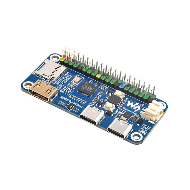
Waveshare RP2040-PiZero is a high-performance and cost-effective microcontroller board with onboard DVI interface, TF card slot and PIO-USB port, compatible with Raspberry Pi 40-pin GPIO header, easy to develop and integrate into the products.
Features
RP2040 microcontroller chip designed by Raspberry Pi
Dual-core ARM Cortex M0+ processor, flexible clock running up to 133 MHz
264 KB of SRAM, and 16 MB of onboard Flash memory
Onboard DVI interface can drive most HDMI screens (DVI compatibility required)
Supports using as a USB host or slave via onboard PIO-USB port
Onboard TF card slot for reading and writing TF card
Onboard Lithium battery recharge/discharge header, suitable for mobile scenarios
USB 1.1 with device and host support
Drag-and-drop programming using mass storage over USB
Low-power sleep and dormant modes
2x SPI, 2x I²C, 2x UART, 4x 12-bit ADC, 16x controllable PWM channels
Accurate clock and timer on-chip
Temperature sensor
Accelerated floating-point libraries on-chip
Downloads
Wiki
This camera module adopts a SmartSens SC3336 sensor chip with 3 MP resolution. It features high sensitivity, high SNR, and low light performance and it is capable of a more delicate and vivid night vision imaging effect, and can better adapt to ambient light changes. Also, it is compatible with Luckfox Pico series boards.
Specifications
Sensor
Sensor: SC3336
CMOS size: 1/2.8"
Pixels: 3 MP
Static resolution: 2304x1296
Maximum video frame rate: 30fps
Shutter: Rolling shutter
Lens
Focal length: 3.95 mm
Aperture: F2.0
FOV: 98.3° (diagonal)
Distortion: <33%
Focusing: Manual focus
Downloads
Wiki
Deze zonne-energie management module is ontworpen voor een 6 ~ 24 V zonnepaneel. Hij kan de 3,7 V oplaadbare Li-accu opladen via een zonnepaneel of USB-aansluiting, en biedt een gestabiliseerde uitgangspanning van 5 V / 1 A of 3,3 V / 1 A.De module beschikt over een MPPT (Maximum Power Point Tracking) functie en meerdere beveiligingscircuits, en werkt daarom veilig en met hoge efficiëntie en stabiliteit. Hij is geschikt voor IoT op zonne-energie, toepassingen op laag vermogen en andere energiezuinige projecten.Kenmerken
Ondersteunt MPPT (Maximum Power Point Tracking), waardoor de efficiëntie van het zonnepaneel wordt gemaximaliseerd
Ondersteunt het opladen van accu’s via zonnepaneel / USB-aansluiting
Geschikt voor 6 ~ 24 V zonnepaneel, met DC-002 jack ingang of schroefaansluiting
Een ingebouwde MPPT SET-schakelaar, waarmee u het niveau selecteert wat het dichtst bij het ingangsniveau ligt om de laadefficiëntie te verbeteren
Twee voedingsuitgangen: een USB-poort voor 5 V, en een pinheader voor 3,3 V of 5 V
Een ingebouwde aluminium elektrolytische condensator met hoge capaciteit en een SMD keramische condensator, waardoor de rimpelspanning wordt verminderd, en voor stabiele werking
Een 14500 accuhouder en een PH2.0 accuconnector, voor het aansluiten van meerdere soorten 3,7 V oplaadbare Li-accu’s
Verschillende led-indicatoren, voor het monitoren van het zonnepaneel en de accu
Meerdere beveiligingscircuits: over-laden / over-ontladen / bescherming tegen omgekeerd aansluiten / oververhitting / teveel stroom, voor stabiele werking en veilig gebruik
Specificaties
Zonnecel ingang
6 ~ 24 V (default 6 V)
Opladen
USB
Accu
3,7 V 850 mAh 14500 Li-ion accu (NIET inbegrepen)
USB-ingang
5 V (Micro USB)
5 V uitgang
5 V / 1 A (USB OUT, pin header) 3,3 V / 1 A (pin header)
Cutoff spanning bij opladen
4,2 V ±1%
Over-ontladen beschermingsspanning
2,9 V ±1%
Zonnepaneel oplaad efficiency
~78%
USB oplaad efficiency
~82%
Accu boost output efficiency
~86%
Ruststroom (max)
<2 mA
Bedrijfstemperatuur
-40°C ~ 85°C
Afmetingen
65,2 x 56,2 x 22,9 mm
Opmerking: 14500 accu is NIET inbegrepen.DownloadsWiki
De Solar Power Manager is compatibel met standaard 6 ~ 24 V zonnepanelen. Hij kan de 18650 oplaadbare Li-ion accu’s opladen via een zonnepaneel of een USB-C aansluiting, en biedt een gestabiliseerde uitgang van 5 V / 3 A (met ondersteuning voor meerdere protocollen, waaronder PD/QC/FCP/PE/SFCP).De module beschikt over een MPPT (Maximum Power Point Tracking) functie en meerdere beveiligingscircuits, en werkt daarom veilig en met hoge efficiëntie en stabiliteit. Hij is geschikt voor IoT op zonne-energie, toepassingen op laag vermogen en andere energiezuinige projecten.Kenmerken
Ondersteunt MPPT (Maximum Power Point Tracking), waardoor de efficiëntie van het zonnepaneel wordt gemaximaliseerd
Flexibel accu’s opladen: van zonnepaneel of USB-C voedingsadapter
Compatibel met 6 ~ 24 V zonnepanelen, DC-002 jack ingang of schroefaansluiting
Een ingebouwde MPPT SET-schakelaar, waarmee u het niveau selecteert wat het dichtst bij het ingangsniveau ligt om de laadefficiëntie te verbeteren
Een ingebouwde aluminium elektrolytische condensator met hoge capaciteit en een SMD keramische condensator, waardoor de rimpelspanning wordt verminderd, en voor een stabiele werking
Een ingebouwde accuhouder, geschikt voor 3x 18650 oplaadbare Li-ion accu’s
Verschillende led-indicatoren, voor het monitoren van het zonnepaneel en de accu’s
Meerdere beveiligingscircuits: over-laden / over-ontladen / bescherming tegen omgekeerd aansluiten / oververhitting / teveel stroom, voor een stabiele werking en veilig gebruik
Specificaties
Zonnecel ingang
6~24 V (default 18 V)
Opladen
USB
Accu
3x 18650 Li-ion accu’s (NIET inbegrepen)
USB-ingang
5 V (USB-C, met PD quick charge ondersteuning)
5 V uitgang
5 V / 3 A (USB-OUT, USB-C)
Cutoff spanning bij opladen
4,2 V ±1%
Over-ontladen beschermingsspanning
3.0 V ±1%
Zonnepaneel oplaad efficiency
~78%
USB oplaad efficiency
~93%
Accu boost output efficiency
~90%
Ruststroom (max)
<2 mA
Behuizing
Metalen behuizing
Bedrijfstemperatuur
-40°C ~ 85°C
Afmetingen
119,0 x 71,0 x 25,2 mm
Inbegrepen
1x Solar Power Manager (C)
1x Adapter
DownloadsWiki
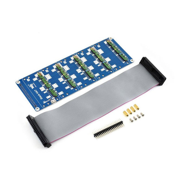
This is an I/O expansion kit designed for Raspberry Pi, which provides 5 sets of 2x20 pinheaders, that means a handy way to 'stack' multi different HATs together, and use them as a specific combination / project. Features Standard Raspberry Pi connectivity, directly pluggable OR through ribbon cable 5 sets of 2x20 pinheaders, connect multi HATs together USB external power port, provides enough power supply for multi HATs Clear and descriptive pin labels for easy use Reserved jumper pads on the bottom side, pin connections are changeable by soldering, to avoid pin conflicts Note: make sure there are no any pin conflicts between the HATs you want to use together before connecting. Specifications Dimensions: 183 × 65 mm Mounting hole size: 3 mm Included 1x Stack HAT 1x Ribbon cable 40-Pin 1x 2x20 male pinheader 1x RPi screws pack (4pcs) x1
WCH CH32V307 RISC-V development board features 8 UART ports controlled over Ethernet The CH32V307 is an interconnected microcontroller, based on 32-bit RISC-V core, with hardware stack area and fast interrupt entry. Compared with standard RISC-V, the interrupt response speed is greatly improved. With single-precision float point instruction sets added and stack area extended, the CH32V307 has higher performance, the number of U(S)ART is extended to 8, and the number of motor timer is extended to 4. The CH32V307 provides USB2.0 high-speed interface (480 Mbps) and has built-in PHY transceiver. Ethernet MAC is upgraded to GbE and integrates 10M PHY module. Features RISC-V4F processor, max 144 MHz system clock frequency Single-cycle multiplication and hardware division, hardware float point unit (FPU) 64KB SRAM, 256 KB Flash Supply voltage: 2.5 V/3.3 V, GPIO unit is supplied independently Multiple low-power modes: sleep/stop/standby Power-on/power-down reset (POR/PDR), programmable voltage detector (PVD) 2 general DMA controllers, 18 channels in total 4 amplifiers Single true random number generator (TRNG) 2x 12-bit DAC 2-unit 16-channel 12-bit ADC, 16-channel TouchKey 10 timers USB2.0 full-speed OTG interface USB2.0 high-speed host/device interface (built-in 480 Mbps PHY) 3 USARTs, 5 UARTs 2 CAN interfaces (2.0B active) SDIO interface, FSMC interface, DVP 2x I²C, 3x SPI, 2x I²S 80 I/O ports, can be mapped to 16 external interrupts CRC calculation unit, 96-bit unique chip ID Serial 2-wire debug interface Packages: LQFP64M, LQFP100 Downloads Datasheet GitHub
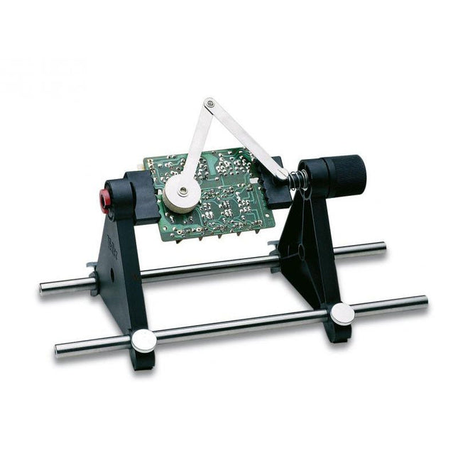
Met de Weller ESF 120ESD PCB-houder fixeert u uw printplaat zonder de noodzaak voor extra benodigdheden of gereedschap. Het frame heeft een veermechanisme en kan 360° om zijn as draaien in stapjes van 15°. De druk-arm is voorzien van een druksysteem om de componenten op hun plaats te houden wanneer de PCB gedraaid wordt voor het solderen. Eigenschappen: Maximale printgrootte 160 x 235 mm Draait 360° in stappen van 15° Klem met veersysteem Druk-arm voor het fixeren van componenten ESD-veilig
Free up your hands and secure and protect your soldering projects with Weller's Helping Hands with 4 Magnetic Arms. Enjoy adjustable and flexible positions with magnetic gooseneck arms with alligator clamps that are easily positionable for multiple configurations. Applications Hobby Home repair Drone Audio repair Joining wires Engraving Jewelry making Electronics Specifications Dimensions (Base) 152 x 229 mm (6 x 9') Length (Arms) 2 arms: 216 mm (8.5')2 arms: 317 mm (12.5')
4 LEDs and 4 push buttons ensure hours of fun. Repeat the combination, harder and harder, faster and faster. The microprocessor-controlled game has 4 different difficulty levels and low consumption. The sound and/or LED indication are adjustable. To save the three 1.5 V AA batteries (not included), the kit automatically switches itself off when not in use.
Downloads
Manual
The Whadda E12 is a high-quality carbon film resistor set comprising 610 pieces, with 10 pieces for each of the 61 standard E12 series values ranging from 10 Ω to 1 MΩ. Each resistor has a power rating of 0.25 W, a tolerance of 5%, and can operate within a temperature range of -55°C to 155°C. The maximum operating voltage is 250 V.
These resistors are suitable for applications in TVs, audio and video equipment, telephone receivers, communication systems, instrumentation, and home appliances.
The Christmas tree with flashing LEDs takes the coziness of Christmas to a new level! With 16 flashing LEDs, this green Christmas tree creates a warm atmosphere. With very low power consumption and the option to be powered by a 9-volt battery (not included), this Christmas decoration is easy to use.
Enjoy the holidays with this atmospheric addition to your decoration collection.
Downloads
Manual
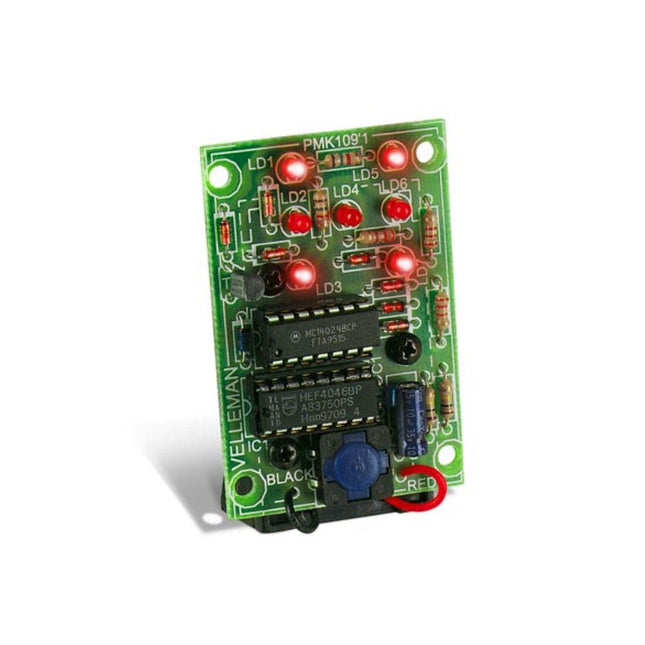
Valentine's Hearts, 28 blinking LEDs, romantic LED lighting Valentine's Hearts – 28 blinking LEDs for a romantic atmosphere. The perfect Valentine's gift to express your love. Battery-powered and portable, ideal for Valentine's Day.
Downloads
Manual
This educational soldering kit is suitable for all kinds of applications such as model making and works with a 9 V battery (not included). You can control the flashing speed with two potentiometers.
Downloads
Manual
The Theremin was the first music synthesizer. The Junior Theremin is our, smaller, version of that classic electronic musical instrument. As you move your hand towards and away from the wire aerial, the Theremin responds by changing the pitch of the note it is playing. It can play individual notes as well as varying the tone of a single note.
How do you use the theremin?
The wire aerial responds to the movement of your hand towards and away from it and changes the pitch of the note it plays, without actually being touched. Junior Theremin works in two modes – continuous and discrete. When you first connect the battery Junior Theremin is in continuous mode. Pressing both pushbuttons together switches between continuous and discrete modes. Discrete mode, as its name implies, plays individual or discrete notes rather than a continuously variable tone. Eight notes over a single octave are available. In discrete mode the two pushbuttons change the octave of the notes. The left-hand pushbutton (marked -) lowers the octave, and the right-hand pushbutton (marked +) raises the octave. The pushbuttons only change the octave so long as they are pressed. In continuous mode the pushbuttons have no effect.
Downloads
Manual