Producten
-

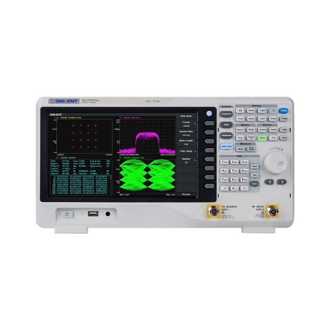
Siglent Siglent SSA3015X Plus Spectrum Analyzer (9 kHz 1,5 gHz)
De Siglent SSA3015X Plus spectrum analyzer is een krachtig en flexibel hulpmiddel voor RF signaal- en netwerkanalyse. Met een frequentiebereik van 1,5 GHz levert de analyzer betrouwbare automatische metingen en meerdere werkingsmodi: spectrum analyzer als basisfunctie, en optionele functies als RF-vermogensmeting, vectorsignaal-modulatieanalyse, reflectiemeting en EMI-test.Toepassingen zijn onder meer monitoring/evaluatie van zendsignalen, metingen op locatie, S-parameter meting, analoge/digitale modulatie analyse, EMI pre-compliance test, onderzoek en ontwikkeling, onderwijs, productie en onderhoud.Kenmerken Spectrum analyzer frequentiebereik van 9 kHz tot 1,5 GHz –156 dBm/Hz Displayed Average Noise Level (typ.) –99 dBc/Hz. @ 10 kHz Offset Phase Noise (1 GHz, typ.) Level Measurement Uncertainty< 1,2 dB (typ.) 1 Hz minimale Resolution Bandwidth (RBW) Voorversterker (standaard) Tracking generator (inbegrepen, gratis) Analoge en digitale signaalmodulatie-analyse modus (optioneel) Reflectie meetkit (optioneel) EMI filter en quasi-peak detector kit (optioneel) Advanced Measurement Kit (optioneel) 10,1-inch multi-touch scherm, muis en toetsenbord ondersteund Webbrowser afstandsbediening op pc en mobiele terminals, en bediening via files Specificaties SSA3015X Plus SSA3021X Plus SSA3032X Plus SSA3075X Plus Frequentiebereik 9 kHz ~ 1,5 GHz 9 kHz ~ 2,1 GHz 9 kHz ~ 3,2 GHz 9 kHz ~ 7,5 GHz Resolutie bandbreedte 1 Hz ~ 1 MHz 1 Hz ~ 1 MHz 1 Hz ~ 1 MHz 1 Hz ~ 3 MHz Phase Noise <–99 dBc/Hz <–98 dBc/Hz <–98 dBc/Hz <–98 dBc/Hz Total Amplitude Accuracy < 1,2 dB < 0,7 dB < 0,7 dB < 0,7 dB Display Average Noise Level –156 dBm/Hz –161 dBm/Hz –161 dBm/Hz –165 dBm/Hz Inbegrepen Siglent SSA3015X Plus spectrum analyzer USB kabel Netsnoer Quick Start gids Downloads Datasheet Manual Documentation Firmware
€ 1.402,39
-

Siglent Siglent SSA3021X Plus Spectrum Analyzer (9 kHz - 2,1 GHz)
De Siglent SSA3021X Plus spectrum analyzer is een krachtig en flexibel hulpmiddel voor RF signaal- en netwerkanalyse. Met een frequentiebereik van 2,1 GHz levert de analyzer betrouwbare automatische metingen en meerdere werkingsmodi: spectrum analyzer als basisfunctie, en optionele functies als RF-vermogensmeting, vectorsignaal-modulatieanalyse, reflectiemeting en EMI-test. Toepassingen zijn onder meer monitoring/evaluatie van zendsignalen, metingen op locatie, S-parameter meting, analoge/digitale modulatie analyse, EMI pre-compliance test, onderzoek en ontwikkeling, onderwijs, productie en onderhoud. Kenmerken Spectrum analyzer frequentiebereik van 9 kHz tot 2,1 GHz –161 dBm/Hz Displayed Average Noise Level (typ.) –98 dBc/Hz. @ 10 kHz Offset Phase Noise (1 GHz, typ.) Level Measurement Uncertainty< 0,7 dB (typ.) 1 Hz minimale Resolution Bandwidth (RBW) Voorversterker (standaard) Tracking generator (inbegrepen, gratis) Analoge en digitale signaalmodulatie-analyse modus (optioneel) Reflectie meetkit (optioneel) EMI filter en quasi-peak detector kit (optioneel) Advanced Measurement Kit (optioneel) 10,1-inch multi-touch scherm, muis en toetsenbord ondersteund Webbrowser afstandsbediening op pc en mobiele terminals, en bediening via files Specificaties SSA3015X Plus SSA3021X Plus SSA3032X Plus SSA3075X Plus Frequentiebereik 9 kHz ~ 1,5 GHz 9 kHz ~ 2,1 GHz 9 kHz ~ 3,2 GHz 9 kHz ~ 7,5 GHz Resolutie bandbreedte 1 Hz ~ 1 MHz 1 Hz ~ 1 MHz 1 Hz ~ 1 MHz 1 Hz ~ 3 MHz Phase Noise <–99 dBc/Hz <–98 dBc/Hz <–98 dBc/Hz <–98 dBc/Hz Total Amplitude Accuracy < 1,2 dB < 0,7 dB < 0,7 dB < 0,7 dB Display Average Noise Level –156 dBm/Hz –161 dBm/Hz –161 dBm/Hz –165 dBm/Hz Inbegrepen Siglent SSA3021X Plus spectrum analyzer USB kabel Netsnoer Quick Start gids Downloads Datasheet Manual Documentation Firmware
€ 1.777,49
-

Siglent Siglent SSA3032X Plus Spectrum Analyzer (9 kHz - 3,2 GHz)
De Siglent SSA3032X Plus spectrum analyzer is een krachtig en flexibel hulpmiddel voor RF signaal- en netwerkanalyse. Met een frequentiebereik van 3,2 GHz levert de analyzer betrouwbare automatische metingen en meerdere werkingsmodi: spectrum analyzer als basisfunctie, en optionele functies als RF-vermogensmeting, vectorsignaal-modulatieanalyse, reflectiemeting en EMI-test.Toepassingen zijn onder meer monitoring/evaluatie van zendsignalen, metingen op locatie, S-parameter meting, analoge/digitale modulatie analyse, EMI pre-compliance test, onderzoek en ontwikkeling, onderwijs, productie en onderhoud.Kenmerken Spectrum analyzer frequentiebereik van 9 kHz tot 3,2 GHz –161 dBm/Hz Displayed Average Noise Level (typ.) –98 dBc/Hz. @ 10 kHz Offset Phase Noise (1 GHz, typ.) Level Measurement Uncertainty< 0,7 dB (typ.) 1 Hz minimale Resolution Bandwidth (RBW) Voorversterker (standaard) Tracking generator (inbegrepen, gratis) Analoge en digitale signaalmodulatie-analyse modus (optioneel) Reflectie meetkit (optioneel) EMI filter en quasi-peak detector kit (optioneel) Advanced Measurement Kit (optioneel) 10,1-inch multi-touch scherm, muis en toetsenbord ondersteund Webbrowser afstandsbediening op pc en mobiele terminals, en bediening via files Specificaties SSA3015X Plus SSA3021X Plus SSA3032X Plus SSA3075X Plus Frequentiebereik 9 kHz ~ 1,5 GHz 9 kHz ~ 2,1 GHz 9 kHz ~ 3,2 GHz 9 kHz ~ 7,5 GHz Resolutie bandbreedte 1 Hz ~ 1 MHz 1 Hz ~ 1 MHz 1 Hz ~ 1 MHz 1 Hz ~ 3 MHz Phase Noise <–99 dBc/Hz <–98 dBc/Hz <–98 dBc/Hz <–98 dBc/Hz Total Amplitude Accuracy < 1,2 dB < 0,7 dB < 0,7 dB < 0,7 dB Display Average Noise Level –156 dBm/Hz –161 dBm/Hz –161 dBm/Hz –165 dBm/Hz Inbegrepen Siglent SSA3032X Plus spectrum analyzer USB kabel Netsnoer Quick Start gids Downloads Datasheet Manual Documentation Firmware
€ 2.951,19
-
Siglent Siglent SSA3075X Plus Spectrum Analyzer (9 kHz - 7,5 GHz)
De Siglent SSA3015X Plus spectrum analyzer is een krachtig en flexibel hulpmiddel voor RF signaal- en netwerkanalyse. Met een frequentiebereik van 7,5 GHz levert de analyzer betrouwbare automatische metingen en meerdere werkingsmodi: spectrum analyzer als basisfunctie, en optionele functies als RF-vermogensmeting, vectorsignaal-modulatieanalyse, reflectiemeting en EMI-test.Toepassingen zijn onder meer monitoring/evaluatie van zendsignalen, metingen op locatie, S-parameter meting, analoge/digitale modulatie analyse, EMI pre-compliance test, onderzoek en ontwikkeling, onderwijs, productie en onderhoud.Kenmerken Spectrum analyzer frequentiebereik van 9 kHz tot 7,5 GHz –165 dBm/Hz Displayed Average Noise Level (typ.) –98 dBc/Hz. @ 10 kHz Offset Phase Noise (1 GHz, typ.) Level Measurement Uncertainty< 0,7 dB (typ.) 1 Hz minimale Resolution Bandwidth (RBW) Voorversterker (standaard) Tracking generator (inbegrepen, gratis) Analoge en digitale signaalmodulatie-analyse modus (optioneel) Reflectie meetkit (optioneel) EMI filter en quasi-peak detector kit (optioneel) Advanced Measurement Kit (optioneel) 10,1-inch multi-touch scherm, muis en toetsenbord ondersteund Webbrowser afstandsbediening op pc en mobiele terminals, en bediening via files Specificaties SSA3015X Plus SSA3021X Plus SSA3032X Plus SSA3075X Plus Frequentiebereik 9 kHz ~ 1,5 GHz 9 kHz ~ 2,1 GHz 9 kHz ~ 3,2 GHz 9 kHz ~ 7,5 GHz Resolutie bandbreedte 1 Hz ~ 1 MHz 1 Hz ~ 1 MHz 1 Hz ~ 1 MHz 1 Hz ~ 3 MHz Phase Noise <–99 dBc/Hz <–98 dBc/Hz <–98 dBc/Hz <–98 dBc/Hz Total Amplitude Accuracy < 1,2 dB < 0,7 dB < 0,7 dB < 0,7 dB Display Average Noise Level –156 dBm/Hz –161 dBm/Hz –161 dBm/Hz –165 dBm/Hz Inbegrepen Siglent SSA3075X Plus spectrum analyzer USB kabel Netsnoer Quick Start gids Downloads Datasheet Manual Documentation Firmware
€ 7.875,89
-
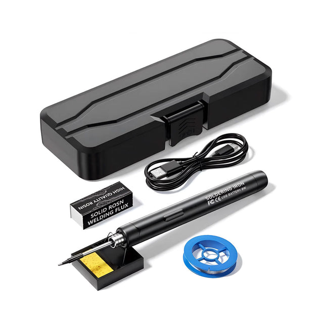
Generic Smart USB Soldeerbout Kit
De Smart USB Soldeerbout Kit is een compacte, draadloze oplossing, ontworpen voor precisie en draagbaarheid. Met intelligente temperatuurregeling met drie snelheden (300-450°C) en een gemakkelijk afleesbaar LED-display, warmt hij op in slechts 10 seconden en smelt het soldeer in slechts 6 seconden. De oplaadbare batterij van 1000 mAh biedt tot 30 minuten continu gebruik, waardoor hij ideaal is voor snelle reparaties, elektronicaprojecten en doe-het-zelfklussen. Met een plug-and-play, vervangbare punt en een hittebestendige, geïsoleerde behuizing is hij veilig, gebruiksvriendelijk en perfect voor zowel beginners als professionals onderweg. Kenmerken Intelligente temperatuurregeling met drie snelheden: Voorzien van een led-display met instelbare temperaturen tussen 300 en 450°C. Schakel eenvoudig tussen Celsius en Fahrenheit. Geïntegreerde plug-in soldeerboutpunt: Plug-and-play ontwerp. De punt kan worden vervangen door deze eenvoudig los te draaien, voor een snelle en gemakkelijke bediening. Veilig en duurzaam ontwerp: Hittebestendige, geïsoleerde behuizing voor extra veiligheid tijdens gebruik. Batterijcapaciteit: Uitgerust met een oplaadbare batterij van 1000 mAh die tot 30 minuten continu gebruik ondersteunt op een volle lading – ideaal voor dagelijkse taken. Efficiënte prestaties: 8 W vermogen met een geïntegreerde verwarmingskern voor snelle opwarming. Smelt tin in slechts 6 seconden en biedt uitstekende thermische geleiding. Gebruiksvriendelijk: Na het inschakelen via USB stelt u de gewenste temperatuur in. De soldeerbout warmt op in 10 seconden. Zodra de soldeerbout klaar is, plaatst u de punt op de standaard – deze koelt binnen 1 minuut af. Perfect voor beginners, hobbyisten, eenvoudige klusjes in huis en het opleiden van ingenieurs. Draadloze innovatie: Deze draadloze soldeerset bevat een ingebouwde oplaadbare lithium-ionbatterij, waardoor kabels niet meer nodig zijn. Veelzijdig te gebruiken voor het solderen van printplaten, elektrische reparaties, het maken van sieraden, metaalbewerking, computeronderhoud en doe-het-zelfprojecten. Specificaties Instelbare temperatuur: 300-450°C Smelttijd tin: <15 seconden Werkspanning: 5 V Uitgangsvermogen: 8 W Batterijcapaciteit: 1000 mAh Automatische slaapfunctie: Activeert na 10 minuten inactiviteit Oplaadtijd: ca. 90 minuten Batterijduur: Tot 30 minuten continu gebruik Oplaadinterface: USB-C Materiaal: Aluminiumlegering Afmetingen: 190 x 16 mm Inbegrepen 1x USB Soldeerbout 1x Soldeerpunt 1x Soldeerhars 1x Soldeerbouthouder (met spons) 1x USB-C oplaadkabel 1x Soldeerdraad 1x Opbergdoos
€ 34,95€ 17,50
Beste prijs
-
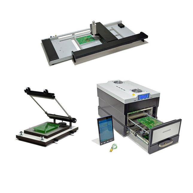
Paggen Werkzeugtechnik SMD Starter I – Productielijn voor prototypes
De SMD Starter I prototype-productielijn bestaat uit de TSD240 stencilprinter, de PlaceMAN SMD-plaatsingsmachine en de 3LHR10 reflow-oven. Stencilprinter SD240 (+ metalen rakel 155 mm) Stencilformaat: max. 175 x 255 mm Boardformaat: max. 180 x 240 mm Afmetingen basiseenheid: 410 x 270 x 110 mm Gewicht: 6,7 kg incl. metalen rakel 155 mm incl. 8 magneten om de printplaat vast te houden, waarvan 6 met M3-instelschroef incl. transparante plaatsingshulp en viltstift Handmatige SMD-plaatsingsmachine PlaceMAN voor standaardcomponenten incl. vacuümpomp (zonder feeders, camera, monitor en dispenser) Uitgerust met soepel lopende plaatsingsarm, plaatsingskop met eenhandsbediening, rotatie van de Z-as en automatische vacuümafsluiting, incl. printplaathouder, vacuümunit en 2 plaatsingsmondstukken met rubberen zuignappen. Capaciteit feeders (niet inbegrepen) 2x invoercassette voor 10 x 8 mm rollen links 4x invoercassette voor toevoereenheden van elk 5 magazijnen Verdere toevoersystemen zijn mogelijk binnen het plaatsingsgebied, bijvoorbeeld een insteeksysteem voor strooktoevoer. Afmetingen Basiseenheid (LxBxH): 765 x 390 x 210 mm Met invoercassette voor 10 x 8 mm rollen (LxBxH): 765 x 390 x 210 mm Met voedingscassette voor 10 x 8 mm rollen en voedingscassette voor magazijninvoer (LxBxH): 765 x 430 x 210 mm (hoogte kan variëren afhankelijk van de lengte van het magazijn) Met voedingscassette voor 10 x 8 mm rollen incl. houder voor 10 rollen en voedingscassette voor magazijninvoer (LxBxH): 765 x 430 x 210 mm (hoogte kan variëren afhankelijk van de lengte van het magazijn) Specificaties Gewicht basiseenheid: ca. 6 kg As verplaatsing (x,y,z): 470 x 230 x 15 mm Max. Werkgebied: 380 x 240 mm Max. PCB-formaat: 230 x 360 mm Voeding Netadapter: 230/12 V, 800 mA Voeding vacuümpomp: 230 V, 6 W 3LHR10 Reflow Oven (programmeerbaar voor loodvrij solderen met handmatige lade en met tabletbediening) Reflow-oven met IR- en convectieverwarming. Geforceerde hete lucht convectie zorgt voor een gelijkmatig temperatuurprofiel in de hele oven. Na het handmatige openen van de afsluiting worden de ventilatoren ingeschakeld en wordt de gesoldeerde printplaat snel afgekoeld. Kleine reflow-oven met handmatige opening Klaar voor Industrie 4.0, Bluetooth-communicatie + tablet IR + convectieverwarming. Android-app voor verbinding met tablet of smartphone 100 verschillende gebruikersprogramma's Leveringsomvang: 3LHR10, tablet met app, beschermhoes voor tablet, 4 printplaathouders, extern thermokoppel, handleiding in tablet Toepassing Sluit de oven aan op het elektriciteitsnet en sluit de optioneel verkrijgbare afzuigunit (3LFE10S) aan op de luchtafvoeraansluiting. Na de eerste keer inschakelen zoekt de oven naar een tablet of smartphone. Wanneer beide verbonden zijn in de Android-app, selecteer je de programmering van de oven. Hier kunnen de temperatuur en voorverwarmingstijd worden ingesteld, evenals andere dingen. Registreer je met de tablet om de software in zijn geheel te kunnen gebruiken. Als de oven al geprogrammeerd is, kan de gebruiker het proces bedienen met de knoppen en het display aan de voorkant. Er klinkt een toon wanneer het reflow proces is voltooid. Er wordt ook een signaal weergegeven op de tablet/smartphone. De lade moet nu handmatig worden geopend. De Android-app geeft de processtatus, tijd en temperatuur of andere informatie weer. Specificaties Netaansluiting: 230 V, 50 Hz Maximaal vermogen: 3100 W Temperaturen: 50-260°C Afmetingen: 510 x 370 x 340 mm Maximaal gewicht: 16 kg Afmetingen rooster: 350 x 220 mm Maximale afmetingen van de printplaat: 300 x 200 mm Maximale componenthoogte op de PCB: 50 mm boven, 30 mm onder Leveringsomvang Stencilprinter TSD240 SMD-plaatsingsmachine PlaceMAN Reflow-oven 3LHR10
€ 6.549,00
Beste prijs
-
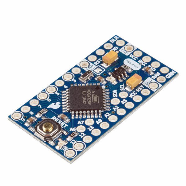
SparkFun SparkFun Arduino Pro Mini 328 (5 V, 16 MHz)
De Arduino Pro Mini is een microcontroller board gebaseerd op de ATmega328P. Het heeft 14 digitale in-/uitgangspinnen (waarvan er 6 kunnen worden gebruikt als PWM-uitgangen), 6 analoge ingangen, een on-board resonator, een reset-knop, en gaten voor het monteren van pin headers. Een six-pin header kan worden aangesloten op een FTDI-kabel of Sparkfun breakout board om USB-voeding en communicatie te bieden aan de board. De Arduino Pro Mini is bedoeld voor semi-permanente installatie in voorwerpen of tentoonstellingen. Het board komt zonder pre-gemonteerde headers, waardoor het gebruik van diverse types van schakelaars of het directe solderen van draden is toegestaan. De pin lay-out is compatibel met Arduino Mini. Specificaties Microcontroller ATmega328P Boord Stroomvoorziening 5-12 V Circuit Werkspanning 5 V Digitale I/O Pinnen 14 PWM Pennen 6 UART 1 SPI 1 I²C 1 Analoge ingangspinnen 6 Externe Onderbrekingen 2 DC stroom per I/O Pin 40 mA Flash Geheugen 32 KB waarvan 2 KB gebruikt door bootloader SRAM 2 KB EEPROM 1 KB Kloksnelheid 16 MHz Afmetingen 18 x 33,3 mm Downloads Eagle files Schematics
€ 14,95€ 7,95
Beste prijs
-

Elektor Digital Starten met Internet of Things (E-book)
35 projecten met Raspberry Pi en wireless Arduino Internet of Things (alles aan het internet) is een trend die zich niet meer laat keren. We willen alles in huis met onze mobiel of tablet doen, van Facebook tot TV kijken, van lichten bedienen tot de temperatuur in de gaten houden. In dit boek laten we in 35 leuke en handige projecten zien hoe u op eenvoudige wijze zelf een Internet of Things systeem kunt aanleggen. We gaan in op de hardware (de perfecte combinatie van Raspberry Pi en Arduino) en de software om bediening via internet mogelijk te maken. We maken gebruik van Wi-Fi en radioverbindingen zodat er geen kabels dwars door uw huis hoeven. Wanneer u deze projecten maakt heeft u een compleet Internet of Things systeem waarmee u van alles in uw huis kunt bedienen en bekijken. Bijvoorbeeld of er post in de brievenbus ligt en of de auto in de garage staat. U kunt op vanaf de bank het licht aandoen en het alarm bedienen. Door de heldere uitleg kunt u de projecten eenvoudig aanpassen om bijvoorbeeld uw koffiezetautomaat of tv op afstand aan te zetten. Via de index vindt u gemakkelijk creatieve projecten die als voorbeeld kunnen dienen, zodat u zelfstandig alles met het internet kunt verbinden.
€ 29,95
Leden: € 26,96
-
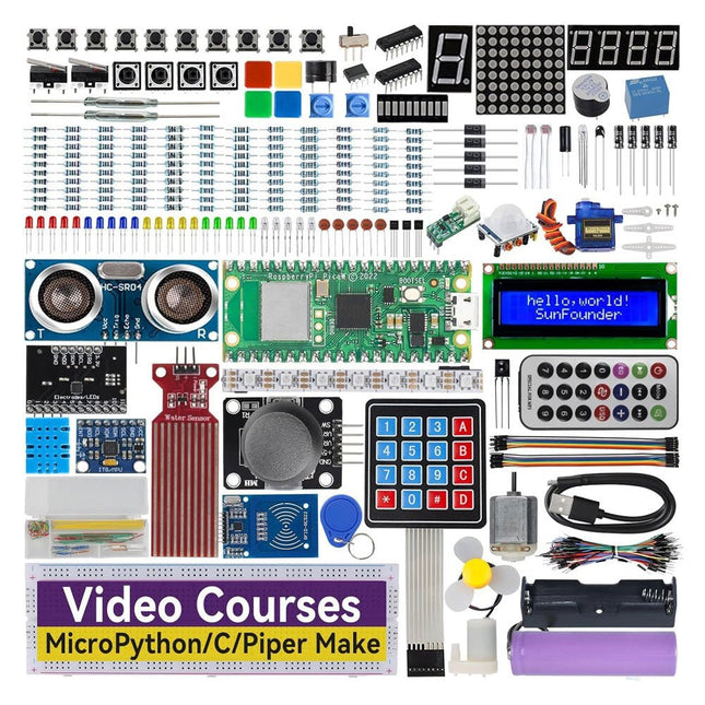
SunFounder SunFounder Kepler Kit (Ultimate Starter Kit voor Raspberry Pi Pico W)
Uw toegangspoort tot IoT en programmeren met microcontrollers Met 450+ componenten en 117 online projecten, stimuleert deze uitgebreide kit uw creativiteit. De tutorials van Paul McWhorter maken leren leuk voor beginners en gevorderde gebruikers. Deze kit ondersteunt MicroPython, C/C++ en Piper Make, en biedt diverse programmeeropties. Ontdek sensoren, actuatoren, LED's en LCD's voor eindeloze projectmogelijkheden. Van huisautomatisering tot robotica, deze kit versterkt uw technische reis. Kenmerken IoT Starter Kit voor beginners: Deze kit biedt een rijke IoT-leerervaring voor beginners. Met 450+ componenten, 117 projecten en door experts geleide videolessen, maakt deze kit het leren van microcontrollerprogrammering en IoT boeiend en toegankelijk. Door experts geleide videolessen: De kit bevat 27 videotutorials van de bekende docent Paul McWhorter. Zijn boeiende stijl vereenvoudigt complexe concepten, wat zorgt voor een effectieve leerervaring in microcontrollerprogrammering. Breed scala aan hardware: De kit bevat een divers scala aan componenten zoals sensoren, actuatoren, LED's, LCD's en meer, waardoor u kunt experimenteren en verschillende projecten kunt maken met de Raspberry Pi Pico W. Ondersteunt meerdere talen: De kit biedt veelzijdigheid met ondersteuning voor drie programmeertalen – MicroPython, C/C++ en Piper Make, wat zorgt voor een gevarieerde programmeerleerervaring. Toegewijde ondersteuning: Profiteer van onze voortdurende assistentie, inclusief een communityforum en tijdige technische hulp voor een naadloze leerervaring. Inbegrepen Raspberry Pi Pico W Breadboard Jumper Wires Weerstand Transistor Condensator Diode Li-po-oplaadmodule 74HC595 TA6586 – Motordriverchip LED RGB-LED LED-staafdiagram Weergave met 7 segmenten 4-cijferige 7-segmentweergave LED-dotmatrix I²C LCD1602 WS2812 RGB-strip met 8 LED's Zoemer DC-motor Servo DC-water Pomp Relais Knop Microschakelaar Schuifschakelaar Potentiometer Infraroodontvanger Joystickmodule 4x4 toetsenbord MPR121-module MFRC522-module Fotoweerstand Thermistor Kantelschakelaar Reedschakelaar PIR-bewegingssensormodule Waterniveausensormodule Ultrasone module DHT11-vochtigheidssensor MPU6050-module Documentatie Online tutorials in 3 talen (EN, DE en JP)
-

Elektor Digital Supersnel PC Interfacen (E-book)
Wilt u in enkele minuten een programma maken op uw PC, dat communiceert met een microcontroller? Dit boek, samen met de Piccolino en gratis software, maakt dat mogelijk!Als hardware wordt gebruik gemaakt van de Piccolino. Dit is een prototype platform met een moderne PIC16F887 microcontroller, dat gebruikt kan worden om razendsnel microcontroller opstellingen te maken. Alle basisvoorzieningen zijn aanwezig op de Piccolino, en door middel van de headers kunnen extra onderdelen eenvoudig aangesloten worden.De Piccolino wordt geprogrammeerd met de krachtige maar eenvoudig te leren gratis programmeertaal JAL. Deze taal wordt zowel door hobbyisten als professionals gebruikt. Bovendien is een serie projectboeken in deze taal verkrijgbaar, en een lesboek waarmee u JAL kunt leren. Aan de PC kant wordt gebruik gemaakt van de eveneens eenvoudig te leren gratis programmeertaal Small Basic van Microsoft. Deze taal is speciaal ontwikkeld om snel Windows programma's te kunnen ontwikkelen, ook voor mensen die weinig of geen PC programmeer ervaring hebben. U leert verschillende technieken om een PC met een microcontroller te laten communiceren zoals losse communicatie, het versterken en verzwakken van signalen, verwerken van valse metingen, master-slave communicatie en synchronisatie met geforceerde reset.Behalve theorie staan in het boek ook 15 leuke en praktische projecten. Door de duidelijke uitleg en instructies kunt u deze projecten zelf uitbreiden en helemaal aan uw eigen wensen aanpassen. Een paar voorbeelden uit het boek: Meet signalen en toon ze op de PC Maak een eigen muis of keyboard besturing. Meet en analyseer componenten (Spoel / Condensator / Transistor / OPAMP) met automatische grafieken op uw PC. Bestuur een servomotor vanaf de PC. Verzamel metingen in de Piccolino en zet ze later over naar uw PC. De combinatie van theorie en praktijkvoorbeelden in dit boek zorgt er voor dat u voor elk interface-probleem een oplossing bij de hand hebt, of weet hoe u er een moet maken.Wat heeft u nodig: Een PC met seriële of USB poort, internetaansluiting en een browser zoals Microsoft Internet Explorer. De gratis download van het softwarepakket (bestand hierboven te vinden), met alle benodigde programma's en voorbeelden De print van het Piccolino-bord is binnenkort verkrijgbaar bij Elektor. Het onderdelenpakket behorende bij dit boek is; verkrijgbaar bij Elektor
€ 29,95
Leden: € 26,96
-

Elektor Digital Technical Modeling with OpenSCAD (E-book)
Create Models for 3D Printing, CNC Milling, Process Communication and Documentation Engineers dread designing 3D models using traditional modeling software. OpenSCAD takes a refreshing and completely different approach. Create your models by arranging geometric solids in a JavaScript-like language, and use them with your 3D printer, CNC mill, or process communication. OpenSCAD differs from other design systems in that it uses programmatical modeling. Your model is made up of primitives that are invoked using a C-, Java- or Python-like language. This approach to model design is close to the “mechanical work” done in the real world and appeals to engineers and others who are not a member of the traditional creative class. OpenSCAD also provides a wide variety of comfort functions that break the 1:1 relationship between code and geometry. This book demonstrates the various features of the programming language using practical examples such as a replacement knob for a LeCroy oscilloscope, a wardrobe hanger, a container for soap dispensers, and various other real-life examples. Written by an engineer with over 15 years of experience, this book is intended for Linux and Windows users alike. If you have programming experience in any language, this book will have you producing practical three-dimensional objects in short order!
€ 29,95
Leden: € 26,96
-

Elektor Publishing Tektronix 7000 Series Mainframes
The Most Iconic Oscilloscopes in Electronics History The 7000 Series was the most iconic family of oscilloscopes in the history of technology. Introduced in 1969 by Tektronix, the sector’s leader at the time, this remarkable line of instruments defined an era and became a benchmark for generations of engineers, researchers, and technicians. Throughout the 1970s and well beyond, 7000-Series oscilloscopes were a constant presence in laboratories, universities, and industrial facilities around the world. Their modular plug-in architecture, exceptional flexibility, and outstanding performance embodied the engineering philosophy that made Tektronix synonymous with accuracy, innovation, and reliability. This book offers an in-depth exploration of the 7000-Series oscilloscopes, combining historical context, technical analysis, and practical insight into their design and restoration. Conceived as a continuation of Tektronix Epic Oscilloscopes, this work expands the subject into two volumes: the first devoted to mainframes and core technologies, the second focused entirely on plug-ins.
€ 69,95
Leden: € 62,96
-
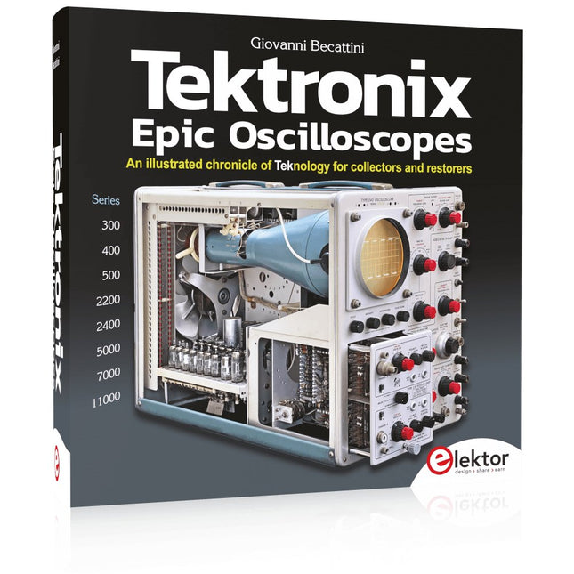
Elektor Publishing Tektronix Epic Oscilloscopes
Een geïllustreerde kroniek van technologienologie voor verzamelaars en restaurateurs Oscilloscopen hebben een belangrijke bijdrage geleverd aan de vooruitgang van de menselijke kennis, niet alleen op het gebied van de elektronica, maar in alle wetenschappen, waar een fysieke grootheid kan worden omgezet in een tijdgerelateerd elektrisch signaal. Dit boek beschrijft de geschiedenis van een cruciaal instrument via vele Tektronix producten. Dit is het bedrijf dat de meeste functies heeft uitgevonden en gepatenteerd die tegenwoordig in alle oscilloscopen te vinden zijn. Tek is en blijft synoniem met de oscilloscoop. In bijna 600 pagina's, met honderden prachtige foto's, diagrammen, anekdotes en technische gegevens, reis je door de geschiedenis van Tektronix in een prachtige verzameleditie met een technisch perspectief. De auteur is niet bang om zijn handen vuil te maken door zijn eigen Tek-apparatuur te restaureren. De reis begint begin jaren vijftig. Het eindigt in de jaren '90, na het verkennen van de ins en outs van de meest interessante modellen in de 300, 400, 500, 5000, 7000 en 11000-serie, van buizen tot geavanceerde hybride technologieën. Downloads NIEUW: Gratis Supplement (136 pagina's, 401 MB)
€ 79,95
Leden: € 71,96
-

Elektor Digital The Arduino-Inside Measurement Lab (E-book)
An 8-in-1 test & measurement instrument for the electronics workbench A well-equipped electronics lab is crammed with power supplies, measuring devices, test equipment and signal generators. Wouldn‘t it be better to have one compact device for almost all tasks? Based on the Arduino, a PC interface is to be developed that’s as versatile as possible for measurement and control. It simply hangs on a USB cable and – depending on the software – forms the measuring head of a digital voltmeter or PC oscilloscope, a signal generator, an adjustable voltage source, a frequency counter, an ohmmeter, a capacitance meter, a characteristic curve recorder, and much more. The circuits and methods collected here are not only relevant for exactly these tasks in the "MSR" electronics lab, but many details can also be used within completely different contexts.
€ 29,95
Leden: € 26,96
-

Elektor Publishing The BeagleY-AI Handbook
A Practical Guide to AI, Python, and Hardware Projects Welcome to your BeagleY-AI journey! This compact, powerful, and affordable single-board computer is perfect for developers and hobbyists. With its dedicated 4 TOPS AI co-processor and a 1.4 GHz Quad-core Cortex-A53 CPU, the BeagleY-AI is equipped to handle both AI applications and real-time I/O tasks. Powered by the Texas Instruments AM67A processor, it offers DSPs, a 3D graphics unit, and video accelerators. Inside this handbook, you‘ll find over 50 hands-on projects that cover a wide range of topics—from basic circuits with LEDs and sensors to an AI-driven project. Each project is written in Python 3 and includes detailed explanations and full program listings to guide you. Whether you‘re a beginner or more advanced, you can follow these projects as they are or modify them to fit your own creative ideas. Here’s a glimpse of some exciting projects included in this handbook: Morse Code Exerciser with LED or BuzzerType a message and watch it come to life as an LED or buzzer translates your text into Morse code. Ultrasonic Distance MeasurementUse an ultrasonic sensor to measure distances and display the result in real time. Environmental Data Display & VisualizationCollect temperature, pressure, and humidity readings from the BME280 sensor, and display or plot them on a graphical interface. SPI – Voltmeter with ADCLearn how to measure voltage using an external ADC and display the results on your BeagleY-AI. GPS Coordinates DisplayTrack your location with a GPS module and view geographic coordinates on your screen. BeagleY-AI and Raspberry Pi 4 CommunicationDiscover how to make your BeagleY-AI and Raspberry Pi communicate over a serial link and exchange data. AI-Driven Object Detection with TensorFlow LiteSet up and run an object detection model using TensorFlow Lite on the BeagleY-AI platform, with complete hardware and software details provided.
€ 44,95
Leden: € 40,46
-

Elektor Digital The BeagleY-AI Handbook (E-book)
A Practical Guide to AI, Python, and Hardware Projects Welcome to your BeagleY-AI journey! This compact, powerful, and affordable single-board computer is perfect for developers and hobbyists. With its dedicated 4 TOPS AI co-processor and a 1.4 GHz Quad-core Cortex-A53 CPU, the BeagleY-AI is equipped to handle both AI applications and real-time I/O tasks. Powered by the Texas Instruments AM67A processor, it offers DSPs, a 3D graphics unit, and video accelerators. Inside this handbook, you‘ll find over 50 hands-on projects that cover a wide range of topics—from basic circuits with LEDs and sensors to an AI-driven project. Each project is written in Python 3 and includes detailed explanations and full program listings to guide you. Whether you‘re a beginner or more advanced, you can follow these projects as they are or modify them to fit your own creative ideas. Here’s a glimpse of some exciting projects included in this handbook: Morse Code Exerciser with LED or BuzzerType a message and watch it come to life as an LED or buzzer translates your text into Morse code. Ultrasonic Distance MeasurementUse an ultrasonic sensor to measure distances and display the result in real time. Environmental Data Display & VisualizationCollect temperature, pressure, and humidity readings from the BME280 sensor, and display or plot them on a graphical interface. SPI – Voltmeter with ADCLearn how to measure voltage using an external ADC and display the results on your BeagleY-AI. GPS Coordinates DisplayTrack your location with a GPS module and view geographic coordinates on your screen. BeagleY-AI and Raspberry Pi 4 CommunicationDiscover how to make your BeagleY-AI and Raspberry Pi communicate over a serial link and exchange data. AI-Driven Object Detection with TensorFlow LiteSet up and run an object detection model using TensorFlow Lite on the BeagleY-AI platform, with complete hardware and software details provided.
€ 34,95
Leden: € 31,46
-

Elektor Publishing The Book of 555 Timer Projects
Over 45 Builds for the Legendary 555 Chip (and the 556, 558) The 555 timer IC, originally introduced by the Signetics Corporation around 1971, is sure to rank high among the most popular analog integrated circuits ever produced. Originally called the IC Time Machine, this chip has been used in many timer-related projects by countless people over decades. This book is all about designing projects based on the 555 timer IC. Over 45 fully tested and documented projects are presented. All projects have been fully tested by the author by constructing them individually on a breadboard. You are not expected to have any programming experiences for constructing or using the projects given in the book. However, it’s definitely useful to have some knowledge of basic electronics and the use of a breadboard for constructing and testing electronic circuits. Some of the projects in the book are: Alternately Flashing Two LEDs Changing LED Flashing Rate Touch Sensor On/Off Switch Switch On/Off Delay Light-Dependent Sound Dark/Light Switch Tone Burst Generator Long Duration Timer Chasing LEDs LED Roulette Game Traffic Lights Continuity Tester Electronic Lock Switch Contact Debouncing Toy Electronic Organ Multiple Sensor Alarm System Metronome Voltage Multipliers Electronic Dice 7-Segment Display Counter Motor Control 7-Segment Display Dice Electronic Siren Various Other Projects The projects given in the book can be modified or expanded by you for your very own applications. Electronic engineering students, people engaged in designing small electronic circuits, and electronic hobbyists should find the projects in the book instructive, fun, interesting, and useful.
€ 34,95
Leden: € 31,46
-

Elektor Digital The Book of 555 Timer Projects (E-book)
Over 45 Builds for the Legendary 555 Chip (and the 556, 558) The 555 timer IC, originally introduced by the Signetics Corporation around 1971, is sure to rank high among the most popular analog integrated circuits ever produced. Originally called the IC Time Machine, this chip has been used in many timer-related projects by countless people over decades. This book is all about designing projects based on the 555 timer IC. Over 45 fully tested and documented projects are presented. All projects have been fully tested by the author by constructing them individually on a breadboard. You are not expected to have any programming experiences for constructing or using the projects given in the book. However, it’s definitely useful to have some knowledge of basic electronics and the use of a breadboard for constructing and testing electronic circuits. Some of the projects in the book are: Alternately Flashing Two LEDs Changing LED Flashing Rate Touch Sensor On/Off Switch Switch On/Off Delay Light-Dependent Sound Dark/Light Switch Tone Burst Generator Long Duration Timer Chasing LEDs LED Roulette Game Traffic Lights Continuity Tester Electronic Lock Switch Contact Debouncing Toy Electronic Organ Multiple Sensor Alarm System Metronome Voltage Multipliers Electronic Dice 7-Segment Display Counter Motor Control 7-Segment Display Dice Electronic Siren Various Other Projects The projects given in the book can be modified or expanded by you for your very own applications. Electronic engineering students, people engaged in designing small electronic circuits, and electronic hobbyists should find the projects in the book instructive, fun, interesting, and useful.
€ 29,95
Leden: € 26,96
-

Elektor Digital The Bottle Builder (E-book)
The author, Johan Basse Bergqvist, is an engineer, a musician, and an audiophile with a knack for building projects that produce the desired results. The combination of these skills leads to a uniquely valuable perspective on audio design that is routinely reflected in the book and passed on to the readers. Several design projects are provided, 40 in total. The designs are explained, and the unique features or methods he uses are described in further detail. Each design includes detailed schematics and a complete parts list. Many of the projects also include layout documentation in the form of CAD photos of the PCB layouts. The range of projects is very diverse and includes something that will appeal to everyone. Stereo amplifiers, guitar and bass amplifiers, preamplifiers for phono, and microphones are all covered. Several variants for each type are included, and the power amplifier designs range from a few watts to several hundred watts, which meet almost any power level you might tackle.
€ 64,95
Leden: € 58,46
-
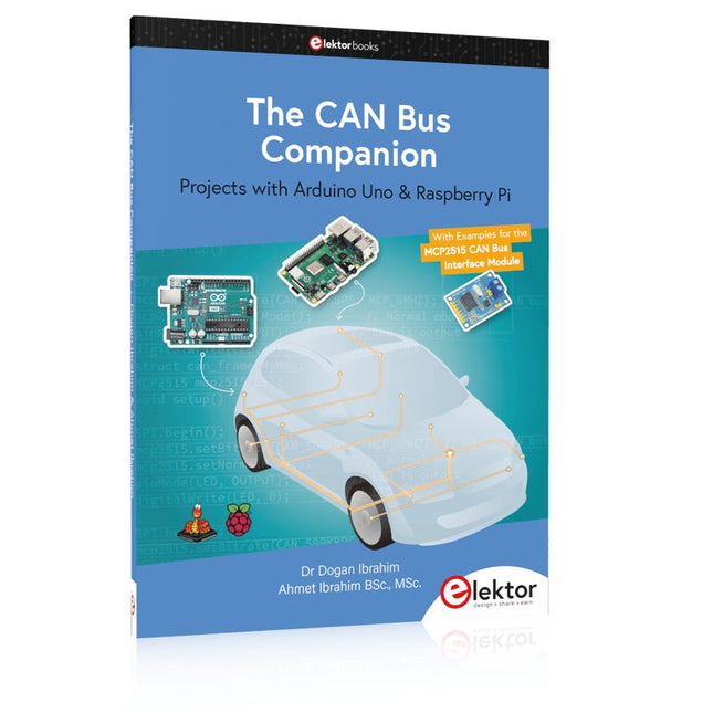
Elektor Publishing The CAN Bus Companion
Projects with Arduino Uno & Raspberry Pi with Examples for the MCP2515 CAN Bus Interface Module This book details the use of the Arduino Uno and the Raspberry Pi 4 in practical CAN bus based projects. Using either the Arduino Uno or the Raspberry Pi with off-the-shelf CAN bus interface modules considerably ease developing, debugging, and testing CAN bus based projects. This book is written for students, practicing engineers, enthusiasts, and for everyone else wanting to learn more about the CAN bus and its applications. The book assumes that the reader has some knowledge of basic electronics. Knowledge of the C and Python programming languages and programming the Arduino Uno using its IDE and Raspberry Pi will be useful, especially if the reader intends to develop microcontroller-based projects using the CAN bus. The book should be a useful source of reference material for anyone interested in finding answers to questions such as: What bus systems are available for the automotive industry? What are the principles of the CAN bus? How can I create a physical CAN bus? What types of frames (or data packets) are available in a CAN bus system? How can errors be detected in a CAN bus system and how dependable is a CAN bus system? What types of CAN bus controllers exist? How do I use the MCP2515 CAN bus controller? How do I create 2-node Arduino Uno-based CAN bus projects? How do I create 3-node Arduino Uno-based CAN bus projects? How do I set the acceptance masks and acceptance filters? How do I analyze data on the CAN bus? How do I create 2-node Raspberry Pi-based CAN bus projects? How do I create 3-node Raspberry Pi-based CAN bus projects?
€ 34,95
Leden: € 31,46
-
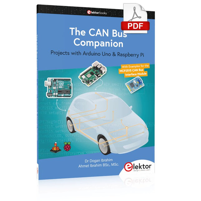
Elektor Digital The CAN Bus Companion (E-book)
Projects with Arduino Uno & Raspberry Pi with Examples for the MCP2515 CAN Bus Interface Module This book details the use of the Arduino Uno and the Raspberry Pi 4 in practical CAN bus based projects. Using either the Arduino Uno or the Raspberry Pi with off-the-shelf CAN bus interface modules considerably ease developing, debugging, and testing CAN bus based projects. This book is written for students, practicing engineers, enthusiasts, and for everyone else wanting to learn more about the CAN bus and its applications. The book assumes that the reader has some knowledge of basic electronics. Knowledge of the C and Python programming languages and programming the Arduino Uno using its IDE and Raspberry Pi will be useful, especially if the reader intends to develop microcontroller-based projects using the CAN bus. The book should be a useful source of reference material for anyone interested in finding answers to questions such as: What bus systems are available for the automotive industry? What are the principles of the CAN bus? How can I create a physical CAN bus? What types of frames (or data packets) are available in a CAN bus system? How can errors be detected in a CAN bus system and how dependable is a CAN bus system? What types of CAN bus controllers exist? How do I use the MCP2515 CAN bus controller? How do I create 2-node Arduino Uno-based CAN bus projects? How do I create 3-node Arduino Uno-based CAN bus projects? How do I set the acceptance masks and acceptance filters? How do I analyze data on the CAN bus? How do I create 2-node Raspberry Pi-based CAN bus projects? How do I create 3-node Raspberry Pi-based CAN bus projects?
€ 29,95
Leden: € 26,96
-

Elektor Digital The Complete ESP32 Projects Guide (E-book)
59 Experiments with Arduino IDE and Python The main aim of this book is to teach the Arduino IDE and MicroPython programming languages in ESP32 based projects, using the highly popular ESP32 DevKitC development board. Many simple, basic, and intermediate level projects are provided in the book using the Arduino IDE with ESP32 DevKitC. All projects have been tested and work. Block diagrams, circuit diagrams, and complete program listings of all projects are given with explanations. In addition, several projects are provided for programming the ESP32 DevKitC using MicroPython. The projects provided in this book are designed to teach the following features of the ESP32 processor: GPIOs Touch sensors External interrupts Timer interrupts I²C and I²S SPI PWM ADC DAC UART Hall sensor Temperature sensor Infrared controller Reading and writing to SD card Reading and writing to flash memory RTC timer Chip ID Security and encryption Wi-Fi and network programming Bluetooth BLE programming Communication mobile devices Low power design ESP-IDF programming The projects have been organized with increasing levels of difficulty. Readers are encouraged to tackle the projects in the order given. A specially prepared hardware kit (SKU 18305) is available from Elektor. With the help of this hardware, it should be easy and fun to build the projects in this book.
€ 34,95
Leden: € 31,46
-

Elektor Classics The Complete Linear Audio Library (USB-stick)
Jan Didden schiep Linear Audio in 2010 en publiceerde 14 delen tussen 2010 en 2017. Elk deel van 200 bladzijden bevat gemiddeld 10 artikelen van deskundige auteurs op het gebied van audio, akoestiek, en instrumentatie. Of je nu geïnteresseerd bent in buizenversterkers, solid-state apparatuur, luidsprekerontwerp, condensator- en weerstandsvervorming of vervormingsmeting, je vindt er zeker nuttige adviezen en interessante discussies. Van beginner tot gevorderd niveau, voor de audio professional of de serieuze hobbyist, deze ExpertCollection zal je kennis vergroten en nieuwe perspectieven bieden op veel voorkomende problemen. Bonusmateriaal bij deze collectie is een 5-delige YouTube serie over negatieve feedback toegepast op audio van de bekende auteur Jan Didden, en nog negen andere baanbrekende audio artikelen en presentaties. Als je serieus geïnteresseerd bent in audio, akoestiek, en instrumentatie, mag je dit niet missen! Het gepubliceerde materiaal is geïndexeerd en volledig doorzoekbaar en zal een bijna onbeperkte bron zijn voor vele jaren. Je kunt over de auteurs van Linear Audio lezen, en de inhoudsopgave van elk deel, zie linearaudio.net.
€ 149,95€ 74,95
Beste prijs
-

Elektor Publishing The Connected Autonomous Vehicle and its Environment
An Introduction to Real and Reduced-Scale Autonomous Vehicles Want to cut through the hype and get to the core of autonomous and connected vehicles? Then this book is your clear, accessible guide to a complex and fast-moving field. Starting with Intelligent Transport Systems (ITS), it walks you through the essential foundations, including Advanced Driver Assistance Systems (ADAS) – the stepping stones to full autonomy. Explore how self-driving cars mimic human behavior through a loop of perception, analysis, decision, and action. Discover the key functions that make it possible: localization, obstacle detection, driver monitoring, cooperative awareness – and the most challenging of all, trajectory planning, across strategic, tactical, and operational levels. Will vehicles be connected? The debate is on – but the standards are already here. Learn how connectivity, infrastructure, and vehicles can work in synergy through the innovative concept of floating car data (FCD). Dive into real-world implementation: with embedded electronics account-ing for over 30% of a modern vehicle‘s cost, we unpack the architecture, coordination, and tools required to manage the complexity – brought to life with a hands-on case study. To finish, we open the door to the future: building your own 1:10 scale autonomous vehicle. No plug-and-play solutions – just the foundations for a collaborative, creative, and geek-friendly challenge. Let’s drive the future together.
€ 34,95
Leden: € 31,46


