Construisez votre station météo idéale ou explorez les données environnementales avec le monde entier. Avec de nombreux projets pratiques pour Arduino, Raspberry Pi, NodeMCU, ESP32 et autres cartes de développement.
Les stations météo jouissent d’une grande popularité depuis des décennies. Tous les magazines d’électronique, qu’ils soient récents ou non, ont publié et publient régulièrement des articles sur la construction d’une station météo. Au fil des années, elles sont devenues de plus en plus sophistiquées et peuvent aujourd’hui être entièrement intégrées dans la maison intelligente. Ceci implique toutefois souvent une fidélité à un fabricant de produits de marque (coûteux) pour tous les composants.
Cependant, avec votre propre station météo, vous pouvez facilement suivre le rythme et même capturer des relevés que les appareils commerciaux ne peuvent pas réaliser. Le plaisir ne manque pas : vous développerez de manière ludique vos connaissances en électronique, en cartes de développement de microcontrôleurs modernes et en langages de programmation. Pour moins de dix euros, vous pouvez collecter des données environnementales initiales et étendre votre système au fur et à mesure que votre intérêt grandit.
Dans ce numéro
Sur la route du vent et de la météo
Écran météo OpenWeatherMap à affichage fluorescent
Les composés organiques volatils dans l‘air que nous respirons
Travailler avec les capteurs MQ : mesurer le monoxyde de carbone
Détecteur de CO2 avec connexion IdO vers ThingSpeak
Un arrosage automatique pour vos plantes
Un climat intérieur sain : la température et l‘humidité de l‘air sont importants
Thermomètre avec tubes Nixie
Une maison météo rétro pour toute la famille
Mesurez la pression atmosphérique et la température avec précision
Un détecteur de coups de soleil
Capteur maison pour la durée d‘ensoleillement
Le smartphone l‘indique : brouillard ou bonne visibilité ?
Détecter les tremblements de terre
Les niveaux des cours d‘eau et des réservoirs
Évaluer la valeur du pH de l’eau
Détecter les rayonnements radioactifs
Avec le GPS, vous savez où se trouve votre capteur
Enregistrer les fichiers journaux avec horodatage sur des cartes SD
LoRaWAN, The Things Network et ThingSpeak
Exploiter la passerelle LoRaWAN pour le TTN
Affichage géant à led avec prévisions météo
Vanaf nu kunt u uw Arduino boards aansluiten met de officiële Arduino USB kabel. Met deze data USB kabel kan uw Arduino board eenvoudig worden verbonden met een door u gekozen apparaat, via een USB-C naar een USB-C met een USB-A adapter. De Arduino USB kabel heeft een nylon gevlochten mantel in de typische Arduino kleuren wit en groenblauw. De connectoren hebben een aluminium omhulsel dat uw kabel beschermt tegen schade en er meteen ook cool uitziet. Lengte: 100 cm Aluminium omhulsel met logo Nylon gevlochten mantel in wit en groenblauw
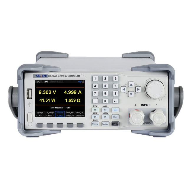
De Siglent SDL1020X-E DC meetsnoeren hebben een meetresolutie van 0,1 mV/0,1 mA en de basis SDL1000X-E serie heeft een resolutie van 1 mV/1 mA en instelbare stroom flankstijgtijden van 0,001 A/?s~2,5 A/?s. Voor communicatie en bediening op afstand bevat de SDL serie S232/USB/LAN interfaces. De SDL1020X-E levert stabiliteit over een breed scala van toepassingen en kan aan allerlei test vereisten voldoen. o.a: Voeding, batterij/handapparaat ontwerp, industrie, LED verlichting, auto-elektronica, en ruimtevaart.
Kenmerken
SDL1020X-E (één kanaal): DC 150 V/30 A, totaal vermogen 200 W
4 Statische modes / Dynamische mode: CC/CV/CR/CP
CC Dynamische stand: Continu, gepulseerd, omgeschakeld
CC Dynamische stand: 25 kHz, CP Dynamische stand: 12,5 kHz, CV Dynamische modus: 0,5 Hz
Meetsnelheid van spanning en stroom: tot 500 kHz
Instelbaar bereik van de stijgtijd van de stroom: 0,001 A/us~2,5 A/us
Min. afleesresolutie: 0,1 mV, 0,1 mA
Kortsluit-, batterijtest-, CR-LED modus-, en fabriekstestfuncties
4-draads SENSE compensatie mode functie
List functie ondersteunt het bewerken van wel 100 stappen
Programmeerfunctie ondersteunt 50 groepen stappen
OCP, OVP, OPP, OTP en LRV beveiliging
Externe analoge regeling
Spanning, stroom bewaking via 0-10 V
3,5 inch TFT-LCD scherm, geschikt voor gelijktijdige weergave van meerdere parameters en toestanden
Ingebouwde RS232/USB/LAN communicatie interface, USB-GPIB module (optioneel)
Trendgrafiek van golfvormen en gemakkelijk te gebruiken functies voor het opslaan en oproepen van bestanden
Inclusief PC software: Ondersteunt SCPI, LabView aandrijving
Inbegrepen
1x Siglent SDL1020X-E DC programmeerbare belasting
1x Snelstartgids
1x Garantiekaart
1x Netsnoer
1x USB kabel
Downloads
Datasheet
Manual
Programming Guide
PC Software
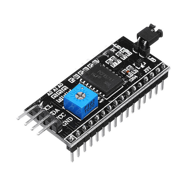
This is another great IIC/I²C/TWI/SPI Serial Interface. As the pin resources of controller is limited, your project may be not able to use normal LCD shield after connected with a certain quantity of sensors or SD card. However, with this I²C interface module, you will be able to realize data display via only 2 wires. If you already has I²C devices in your project, this LCD module actually cost no more resources at all. It is fantastic for based project. I²C Address: 0X20~0X27 (the original address is 0X20,you can change it yourself) The backlight and contrast is adjusted by potentiometer Comes with 2 IIC interface, which can be connected by Dupont Line or IIC dedicated cable I²C Address: 0x27 (I²C Address: 0X20~0X27 (the original address is 0X27,you can change it yourself) Specifications Compatible for 1602 LCD Supply voltage: 5 V Weight: 5 g Size: 5.5 x 2.3 x 1.4 cm
Case for the DPS5005 and DPH5005 Power Supplies Package includes: Metal case Fan Fan power supply board Connection cables Switch Screws Nuts Spacers Forked cable lugs Binding posts Transparent sticky mat
35 Touch Develop & MicroPython Projects
The BBC micro:bit is a credit sized computer based on a highly popular and high performance ARM processor. The device is designed by a group of 29 partners for use in computer education in the UK and will be given free of charge to every secondary school student in the UK.
The device is based on the Cortex-M0 processor and it measures 4 x 5 cm. It includes several important sensors and modules such as an accelerometer, magnetometer, 25 LEDs, 2 programmable push-button switches, Bluetooth connectivity, micro USB socket, 5 ring type connectors, and a 23-pin edge connector. The device can be powered from its micro USB port by connecting it to a PC, or two external AAA type batteries can be used.
This book is about the use of the BBC micro:bit computer in practical projects. The BBC micro:bit computer can be programmed using several different programming languages, such as Microsoft Block Editor, Microsoft Touch Develop, MicroPython, and JavaScript.
The book makes a brief introduction to the Touch Develop programming language and the MicroPython programming language. It then gives 35 example working and tested projects using these language. Readers who learn to program in Touch Develop and MicroPython should find it very easy to program using the Block Editor or any other languages.
The following are given for each project:
Title of the project
Description of the project
Aim of the project
Touch Develop and MicroPython program listings
Complete program listings are given for each project. In addition, working principles of the projects are described briefly in each section. Readers are encouraged to go through the projects in the order given in the book.
In 2011 we published a small PCB, FT232R USB/Serial Bridge/BOB (110553) with a USB-UART IC from FTDI, the FT232RQ. Here we present its successor with a cheaper version, an FT231XQ. But there are some other changes too. Instead of connectors, alongside the PCB, normal pin headers are used that are mounted on the bottom side and make the PCB a little smaller when mounted, compared to the old BoB. An ESD protection device (D1) is added in the USB data signal lines for extra safety. Despite less room for all parts to fit on the PCB, it is only a little over 2 mm longer. The FT231 has four configurable CBUS I/O pins, one less now. More importantly, however, the power supply for the I/O's VCCIO is only specified for +1.8 V to +3.3 but is 5 V tolerant for external UART logic running on +5 V. The +3.3 V internal regulator of the FT231 can deliver 50 mA to external circuitry. The manufacturer FTDI has a utility to configure several settings, FTPROG. Such as the function of the CBUS pins. By default, CBUS1 and CBUS 2 are low-level outputs to drive receive and transmit LEDs, indicating data transfer on the USB bus. So, when receiving data through the UART, the TX LED lights up. If you prefer this the other way around, FTPROG can be used to change this. But be careful the chip can become unresponsive when wrong settings are programmed. Some of the more important properties of the new BoB: Micro-USB connector USB 2.0 Full Speed capable VCCIO +1.8...+3.3 V (max. 4 V, 5 V input from UART logic tolerant) +3.3 V regulator output, max. 50 mA Data transfer 300 baud to 3 Mbaud UART Compatible with RS232, RS485, and RS422 I/O pin output drive 4 mA - 16 mA 4 configurable CBUS pins Here you can find information regarding the EEPROM Programming Utility, the VCP Drivers and the D2XX Drivers.
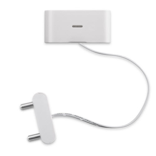
LWL01 is powered by a CR2032 coin battery, in a good LoRaWAN Network Coverage case, it can transmit as many as 12,000 uplink packets (based on SF 7, 14 dB). In poor LoRaWAN network coverage, it can transmit ~ 1,300 uplink packets (based on SF 10, 18.5 B). The design goal for one battery is up to 2 years. User can easily change the CR2032 battery for reuse. The LWL01 will send periodically data every day as well as for water leak event. It also counts the water leak event times and also calculates last water leak duration. Each LWL01 is pre-load with a set of unique keys for LoRaWAN registration, register these keys to local LoRaWAN server and it will auto connect after power on. Features LoRaWAN v1.0.3 Class A SX1262 LoRa Core Water Leak detect CR2032 battery powered AT Commands to change parameters Uplink on periodically and water leak event Downlink to change configure Applications Wireless Alarm and Security Systems Home and Building Automation Industrial Monitoring and Control
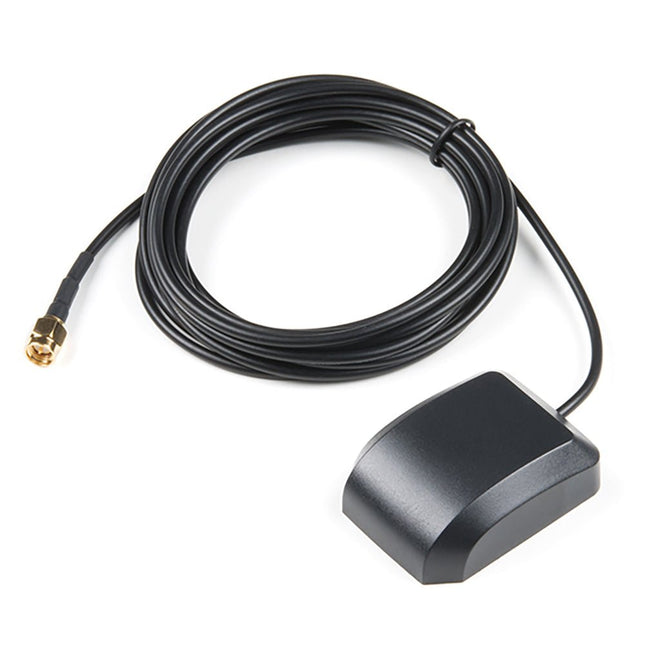
Deze uitzonderlijke GPS/GNSS-antenne is ontworpen voor zowel GPS- als GLONASS-ontvangst. Door de magnetische bevestiging kan de antenne gemakkelijk worden bevestigd op een metalen ondergrond zoals een grondplaat of autodak. De antenne wordt afgesloten met een kabel van 3 m en een standaard SMA-connector.Features
Afmetingen: 50x38x17mm
Gewicht: 75g inclusief 3m kabel
Frequentiebereik: 1575 - 1610MHz
GPS middenfrequentie: 1575.42MHz
GLONASS Center Frequentie: 1602MHz
LNA spanning: 3 tot 5VDC
LNA-versterking: 28dB
LNA Stroom: 10mA
Terminatie Aansluiting: SMA
Impedantie: 50Ω
Rechtse polarisatie
Kabellengte: 3 meter
De Pico Cube is een 4x4x4 led kubus HAT voor Raspberry Pi Pico met 5 VDC bedrijfsspanning. De Pico Cube, een monochromatisch Blauw met 64 leds, leert u op een leuke manier programmeren. Hij is ontworpen om lichtgevende bewerkingen te tonen met een laag energieverbruik, heeft een robuust ontwerp en is eenvoudig te installeren, waardoor mensen / kinderen / gebruikers de effecten op leds met een verschillend kleurenpatroon leren kennen door software en hardware, zoals de Raspberry Pi Pico, te combineren. Kenmerken Standaard 40-pins Raspberry Pi Pico header GPIO-gebaseerde communicatie 64 high-intensity monochromatische leds Toegang tot individuele leds Toegang tot elke laag Specificaties Bedrijfsspanning: 5 V Kleur: blauw Communicatie: GPIO Leds: 64 Inbegrepen 1x Pico Cube basis PCB 4x PCB lagen 8x PCB pilaren 2x berg strips (1 x 20), male 2x berg strips (1 x 20), female 70 leds Opmerking: Raspberry Pi Pico is niet inbegrepen. Downloads GitHub Wiki
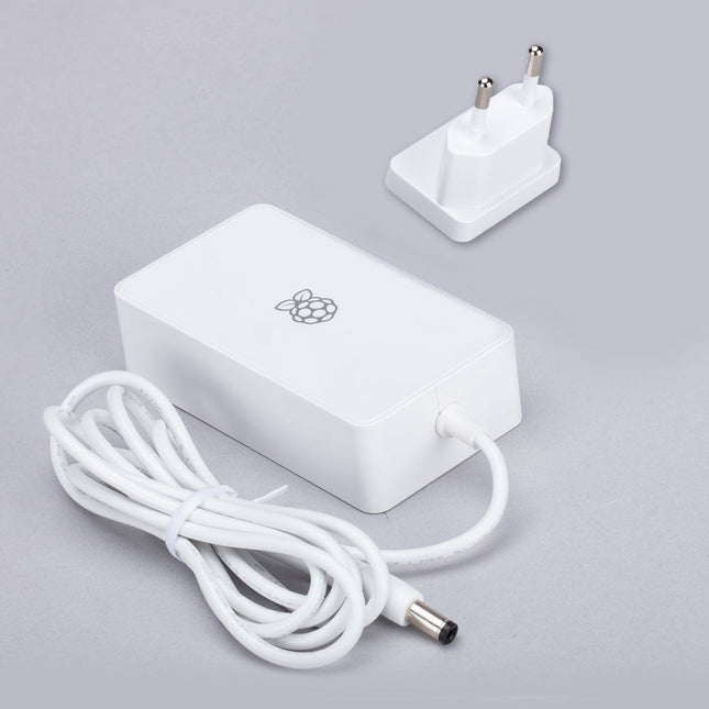
This 48 W (8 VDC, 6 A) power supply is designed for the use with the Raspberry Pi Build HAT. Input: 110-240 VAC
Output: 8 VDC, 6 A Cable: 1.5 m, 16 awg
Het T-Journal is een goedkoop ESP32 Camera Development Board dat is voorzien van een OV2640 camera, een antenne, een 0,91 inch OLED display, enkele blootliggende GPIO's, en een micro-USB interface. Het maakt het gemakkelijk en snel om code te uploaden naar het bord.Specificaties
Chipset Expressif-ESP32-PCIO-D4 240 MHz Xtensa single-/dual-core 32-bit LX6 microprocessor
FLASH QSPI flash/SRAM, tot 4x 16 MB
SRAM 520 kB SRAM
KEY-reset, IO32
Display 0,91' SSD1306
Aan/uit-lampje rood
USB naar TTL CP2104
Camera OV2640, 2 Megapixel
Analoge servo stuurmotor
On-board klok 40 MHz kristal oscillator
Werkspanning 2,3-3,6 V
Werkstroom ongeveer 160 mA
Werkend temperatuurbereik -40? ~ +85?
Afmeting 64,57 x 23,98 mm
Voeding USB 5 V/1 A
Laadstroom 1 A
Batterij 3,7 V lithium batterij
WiFi
Standaard FCC/CE/TELEC/KCC/SRRC/NCC (ESP32-chip)
Protocol 802.11 b/g/n/e/i (802.11n, snelheid tot 150 Mbps) A-MPDU en A-MSDU polymerisatie, ondersteuning 0,4 ?S Beschermingsinterval
Frequentiebereik 2,4 GHz~2,5 GHz (2400 M ~ 2483,5 M)
Zendvermogen 22 dBm
Communicatieafstand 300m
Bluetooth
Protocol voldoet aan bluetooth v4.2BR/EDR en BLE standaard
Radio frequentie met -98 dBm gevoeligheid NZIF ontvanger Klasse-1, Klasse-2 & Klasse-3 emitter AFH
Audio frequentie CVSD & SBC audio frequentie
Software
Wifi-modus Station/SoftAP/SoftAP+Station/P2P
Veiligheidsmechanisme WPA/WPA2/WPA2-Enterprise/WPS
Encryptie Type AES/RSA/ECC/SHA
Firmware-upgrade UART-download/OTA (via netwerk/host om firmware te downloaden en te schrijven)
Softwareontwikkeling Ondersteuning cloud server ontwikkeling /SDK voor gebruiker firmware ontwikkeling
Netwerkprotocol IPv4, IPv6, SSL, TCP/UDP/HTTP/FTP/MQTT
Gebruikersconfiguratie AT + instructieset, cloud server, Android/iOS app
OS FreeRTOS
Inbegrepen
1x ESP32-cameramodule (Fish-eye lens)
1x Wi-Fi-antenne
1x Stroomkabel
DownloadsCamerabibliotheek voor Arduino
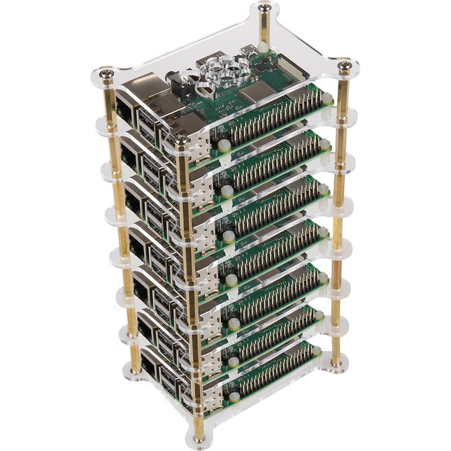
Tower-Case for Raspberry Pi Server Cluster Material Acryl, brass Capacity up to 7 boards Color Transparent Dimensions 75 mm x 104 mm x 202 mm Weight 226 g
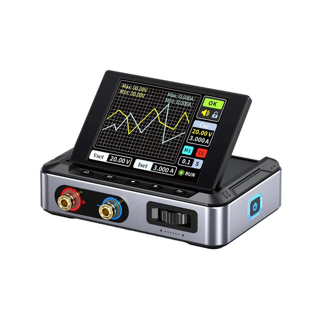
De FNIRSI DPS150 is een krachtige, instelbare DC-voeding met een USB-C-ingangsinterface en meerdere voedingsmodi, waardoor een nauwkeurige aanpassing van de uitgangsspanning (0-30 V) en stroom (0-5 A) mogelijk is.
Het biedt een efficiënte, laag verbruik en stabiele output, uitgerust met meerdere veiligheidsbeschermingsfuncties, waaronder overspanning, overstroom, overbelasting, oververhitting en omgekeerde verbinding. Het kan flexibel worden toegepast op de seriële verbinding van meerdere apparaten, met een rijke en gebruiksvriendelijke weergave en bediening, een compact en draagbaar ontwerp en voldoet aan verschillende toepassingsbehoeften.
Kenmerken
30 V, 5 A, 150 W variabel gelijkstroomvermogen met 0,01 V, 0,001 A precisie, CC/CV-modi en <20 mV rimpel om gevoelige elektronica te beschermen.
Ondersteunt pc-, QC- en DC-ingangen met programmeerbare uitgangen en 6 vooraf ingestelde spannings-/stroominstellingen.
Compatibel met 4 mm banaanstekkers, U-vormige aansluitingen en koperdraden voor diverse apparatuur.
8 veiligheidsmechanismen, waaronder bescherming tegen overspanning, stroom, kortsluiting en oververhitting.
2,8-inch HD IPS-scherm met 90° flip-, numerieke en curve-displays voor eenvoudige monitoring.
Klein, ruimtebesparend ontwerp voor gebruik in laboratoria, reparaties en doe-het-zelf-projecten.
Specificaties
Ingangsspanning
5~32 V DC
Ingangsstroom
100 mA-5 A
Uitgangsspanning
0-30 V
Uitgangsstroom
0~5 A
Uitgangsvermogen
0-150 W
Input way
PD-snellader
QC snellader
Powerbank
DC-voedingsadapters
Bedrijfsomgeving
0-40°C
Belastingsregeling
0,49%
Efficiëntie bij volledige belasting
96,30%
Display
2,8 inch (320 x 240)
Afmetingen
106 x 76 x 28 mm
Gewicht
178 g
Inbegrepen
1x DPS150 voeding
2x Krokodillenklemdraden (zwart en rood)
1x Micro-USB-kabel
1x Manual
Downloads
Manual
Firmware V0.0.1
De EggBot is een gemakkelijk te bedienen open-source robot, die allerlei vormen kan tekenen op bolvormige en eivormige voorwerpen. De EggBot heeft een groot aantal instelmogelijkheden en kan bijvoorbeeld tekenen en op eieren, maar ook golfballen, gloeilampen, kerstballen en zelfs wijnglazen.
Mogelijkheden van de EggBot Deluxe
Gebruik de bot om indrukwekkende paaseieren te creëren, maak uw eigen kerstversiering of personaliseer uw golfballen. De EggBot is niet alleen een cool gadget, het biedt ook een geweldige introductie in de wereld van CNC (Computer Numerical Control) en doe-het-zelf robotica. Alle elektronica en software in de Eggbot kunt u aanpassen en zelfs voor andere toepassingen gebruiken.
Hoe werkt de robot?
De EggBot wordt aangeboden in vorm van een bouwpakket en wordt geleverd inclusief een universele netvoeding (met US-EU-adapter). De Eggbot is makkelijk in elkaar te zetten in een paar uur en heeft alleen een paar basis tools nodig zoals een platte schroevendraaier. Solderen is niet nodig.
Met behulp van de EggBot-software, open source, kunt u deze machine aansturen vanuit Inkscape, een uitstekend freeware illustratieprogramma (voor Mac-, Windows-en Linux-computers). U kunt zelf een afbeelding tekenen, een foto inscannen of ontwerpen uit andere programma's importeren. U kunt de EggBot ook vanuit veel andere programma’s aansturen wanneer deze de mogelijkheid bezitten om seriële commando’s te versturen via een USB-poort.
Een retro-rol met een neonziel
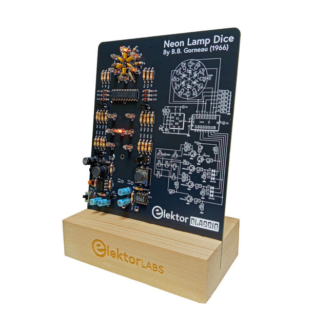
Dobbelstenen met leds zijn gebruikelijk, maar hun licht is koud. Dat geldt niet voor deze elektronische neon-dobbelsteen, die zijn waarde toont met de warme gloed van neonlampen. Hij is perfect om te spelen op koude, donkere winteravonden. De ogen van de dobbelsteen zijn neonlampen en de random number generator heeft zes neonlampen om aan te geven dat hij werkt.
Hoewel de dobbelsteen een ingebouwde 100 V-voeding heeft, is hij volkomen veilig. Zoals bij alle Elektor Classic-producten is ook bij de dobbelsteen het schema op de voorkant afgedrukt, terwijl een uitleg over de werking van de schakeling op de achterkant te vinden is.
De neonlamp-dobbelsteen wordt geleverd als een bouwpakket met eenvoudig te solderen doorlopende onderdelen. De voeding is een 9 V-batterij (niet meegeleverd).
Kenmerken
Warme vintage gloed
Elektor Heritage Circuit Symbolen
Getest en getest door Elektor Labs
Educatief en geeky project
Alleen doorlopende onderdelen
Inbegrepen
Printplaat
Alle componenten
Houten standaard
Vereist
9 V batterij
Stuklijst
Weerstanden (THT, 150 V, 0.25 W)
R1, R2, R3, R4, R5, R6, R14 = 1 MΩ
R7, R8, R9, R10, R11, R12 = 18 kΩ
R13, R15, R16, R17, R18, R21, R23, R24, R25, R26, R28, R30, R33 = 100 kΩ
R32, R34 = 1.2 kΩ
R19, R20, R22, R27, R29 = 4.7 kΩ
R31 = 1 Ω
Condensatoren
C1, C2, C3, C4, C5, C6 = 470 nF, 50 V, 5 mm pitch
C7, C9, C11, C12 = 1 µF, 16 V, 2 mm pitch
C8 = 470 pF, 50 V, 5 mm pitch
C10 = 1 µF, 250 V, 2.5 mm pitch
Spoelen
L1 = 470 µH
Halfgeleiders
D1, D2, D3, D4, D5, D6, D7 = 1N4148
D8 = STPS1150
IC1 = NE555
IC2 = 74HC374
IC3 = MC34063
IC4 = 78L05
T1, T2, T3, T4, T5 = MPSA42
T6 = STQ2LN60K3-AP
Diversen
K1 = PP3 9 V batterijhouder
NE1, NE2, NE3, NE4, NE5, NE6, NE7, NE8, NE9, NE10, NE11, NE12, NE13 = neonlicht
S2 = Miniatuurschuifschakelaar
S1 = Drukknop (12 x 12 mm)
De Aoyue 8486 rookafzuiger maakt gebruik van 3 filters, waaronder HEPA en actieve koolkorrels, die zorgen voor een maximale extractie efficiëntie. Dit verwijdert 97% van de deeltjes groter dan 0,3 um. Plaats de arm van de rookafzuiger eenvoudig boven het soldeerwerk, daar waar u de rook verwacht. Kies het juiste vermogen voor de rookafzuiging met behulp van de bedieningsknop en de grote uitlezing op het voorpaneel. De Aoyue 8486 zuigt dan soldeerrook, veroorzaakt door smeltend vloeimiddel en andere dampen, weg van uw gezicht zodat u vrij kunt ademen. Kenmerken Desktop rookafzuigsysteem met HEPA-filter (high efficiency particulate air filter) voor het verwijderen van stofdeeltjes en een verbeterd actief koolstof filtratiesysteem. Met echte koolstof filterkorrels. Grote zuigkracht, stille werking. Elektronisch bedieningspaneel met variabele luchtstroomregeling. Subfilters verlengen de levensduur van de hoofdfilters. Vrijstaande afzuigarm. Afzuigarm kan naar wens worden gebogen en behoudt vorm na verdraaiing. Het apparaat heeft montagegaten zodat hij aan de muur kan worden bevestigd om zo bureauruimte vrij te maken. Specificaties Voeding 220 V DC spanning 12 V Zuigventilator 3,59 m/s Zuigkracht 18-100% HEPA-filter H11 class Koolstoffilter Activated carbon 800 IV (cilinder type) Afmetingen 184 x 184 x 152 mm (B x H x D) Gewicht 1,8 kg Inbegrepen Basisstation Flexibele afzuigarm Filterkap HEPA-filter Actief koolstoffilter Sub-luchtfilter DC voeding Gebruiksaanwijzing
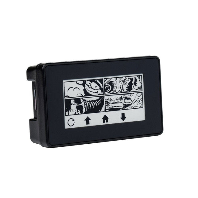
Features
2.13' capacitive touch e-Paper display, 5-point touch, 250×122 pixels
Supports waken up by user-defined gesture
No backlight, keeps displaying last content for a long time even when power down
Ultra low power consumption, basically power is only required for refreshing
Standard Raspberry Pi 40PIN GPIO extension header, supports Raspberry Pi Zero / Zero W
Comes with development resources and manual (examples for Raspberry Pi)
Included
1x 2.13inch Touch e-Paper HAT
1x ABS case
1x Screwdriver
1x Thermal tape
1x Rubber feet 4pcs
2x Screws
Downloads
Documentation
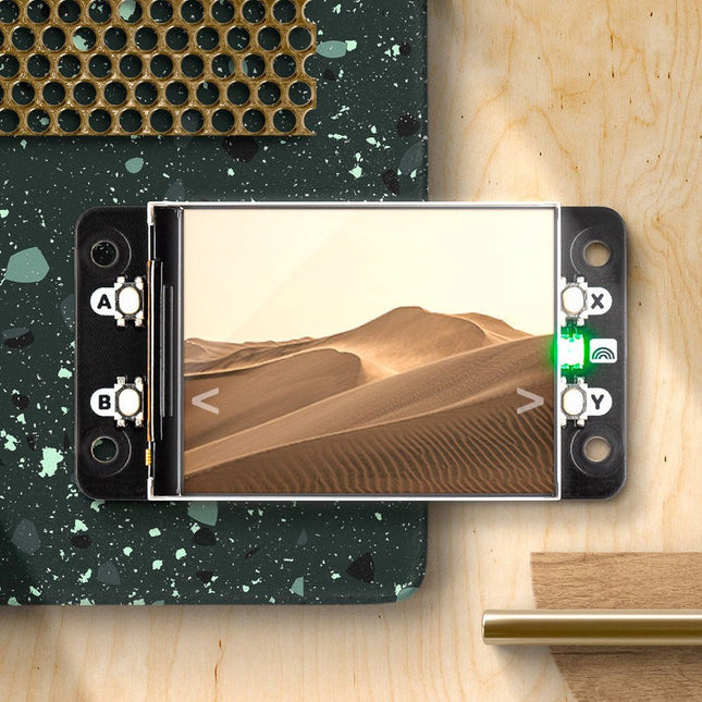
Display HAT Mini features a bright 18-bit capable 320x240 pixel display with vibrant colours and formidable IPS viewing angles, connected via SPI. It's got four tactile buttons for interacting with your Raspberry Pi with your digits and a RGB LED for notifications. A QwST connector (Qwiic / STEMMA QT) and a Breakout Garden header is also squeezed in so it's a doddle to connect up different kinds of breakouts.It will work with any model of Raspberry Pi with a 40 pin header, but we think it goes with the Raspberry Pi Zero particularly well - we've included a pair of standoffs so you can use to bolt HAT and Raspberry Pi together to make a sturdy little unit. To accommodate the screen Display HAT Mini is a bit bigger than a standard mini HAT or pHAT – it's around 5 mm taller than a Raspberry Pi Zero (so a Mini HAT XL or a Mini HAT Pro, if you will).Display HAT Mini lets you turn a Raspberry Pi into a convenient IoT control panel, a tiny photo frame, digital art display or gif-box, or a desktop display for news headlines, tweets, or other info from online APIs. This screen is a handy 3:2 ratio, useful for retro gaming purposes!Features
2.0” 320x240 pixel IPS LCD screen, connected via SPI (~220 PPI, 65K colours)
4x tactile buttons
RGB LED
Qw/ST (Qwiic/STEMMA QT) connector
Breakout Garden / I²C header
Pre-soldered socket header for attaching to Raspberry Pi
Compatible with all models of Raspberry Pi with a 40-pin header.
Fully assembled
No soldering required (as long as your RPi has header pins attached).
Dimensions: approx 65.5 x 35 x 9 mm (W x H x D, includes header and display). With a Raspberry Pi Zero attached with standoffs, the total depth is 17 mm.
Screen usable area: 40.8 x 30.6 mm (L x W)
Pinout
Schematic
Dimensional drawing
Display HAT Mini Python library
ST7789 Python library
Included
Display HAT Mini
2x 10 mm standoffs
SPIDriver shows you what’s happening on the SPI bus in real time, so no more guessing about the bus state. Its purpose is to make understanding the functioning of SPI hardware more intuitive. It's useful if you're into debugging hardware or simply introduce a class to SPI for the first time.You can directly control LEDs and LCD displays just by having SPIDriver and you won't have to deal with microcontrollers. It's also a useful tool for examining, backing up and cloning an SPI flash as well as reading and writing SPI flash in circuit.SPIDriver is also applicable if you want to drive, test and evaluate different displays.With the help of current and voltage monitoring you'll be able to detect electrical problems at early stages. Thanks to the included color coded wires you can hook SPIDriver up without much effort; no pinout diagram required. It includes 3.3 V and 5 V supplies for your device, plus a high-side current meter.SPIDriver comes with software to control it from:
a GUI
the command-line
C and C++ using a single source file
Python 2 and 3, using a module
Technical features
Live display shows you exactly what it’s doing all the time
Sustained SPI transfers at 500 Kbps
USB line voltage monitor to detect supply problems, to 0.01 V
Target device high-side current measurement, to 5 mA
Two auxiliary output signals, A and B
Two dedicated power outlines: of 3.3 V and 5 V
All signals color coded to match jumper colors
All signals are 3.3 V, and are 5 V tolerant
Uses an FTDI USB serial adapter, and Silicon Labs automotive-grade EFM8 controller
Also reports uptime, temperature, and running CRC of all traffic
All sensors and signals controlled using a simple serial protocol
GUI, command-line, C/C++, and Python 2/3 host software provided for Windows, Mac, and Linux
Details
Maximum power out current: up to 470 mA
Signal current: up to 10 mA
Device current: up to 25 mA
Dimensions: 61 mm x 49 mm x 6 mm
Interface: USB 2.0, micro USB connector
Contents (SPIDriver Core)
1x SPIDriver
1x Set of hookup jumpers
Deze LR1302 module is een LoRaWAN gateway module van de nieuwe generatie. Zijn vormfactor is gebaseerd op mini-PCIe, en hij heeft een laag stroomverbruik en hoge prestaties. Voorzien van de SX1302 LoRaWAN baseband chip van Semtech Network biedt de LR1302 gateway module diverse gateway functies met potentieel de capaciteit voor draadloze transmissie over lange afstanden. Vergeleken met de vorige SX1301 en SX1308 LoRa chips heeft de SX1302 chip een hogere gevoeligheid, een lager stroomverbruik en een lagere bedrijfstemperatuur. Hij ondersteunt 8-kanaals gegevensoverdracht, verbetert de communicatie efficiëntie en capaciteit, en ondersteunt de verbindingen en gegevensoverdracht naar meer apparaten.
Hij heeft twee antenne interfaces, één voor het verzenden en ontvangen van LoRa-signalen en één U.FL (IPEX) interface voor onafhankelijke transmissie. Hij heeft ook een metalen afscherming om te beschermen tegen externe interferentie, en om een betrouwbare communicatieomgeving te bieden.
De LR1302 is speciaal ontworpen voor IoT, en is derhalve geschikt voor een verscheidenheid aan IoT toepassingen. Of het nu gaat om gebruik in smart cities, landbouw, industriële automatisering of andere gebieden, de LR1302 module kan betrouwbare verbindingen en efficiënte gegevensoverdracht bieden.
Kenmerken
Maakt gebruik van de Semtech SX1302 baseband LoRa chip met extreem laag stroomverbruik en uitstekende prestaties
De Mini-PCIe vormfactor en het compact ontwerp maken het gemakkelijker om hem te integreren in verschillende gateway-apparaten, en maakt hem geschikt voor toepassingen met beperkte ruimte, en biedt flexibele implementatieopties
Ondersteuning van 8-kanaals datatransmissie, zorgt voor betere communicatie-efficiëntie en capaciteit
Ultra-lage bedrijfstemperatuur elimineert de noodzaak van extra koeling, en verkleint de afmeting van de LoRaWAN gateway
Gebruikt het SX1250 TX/RX front-end met een gevoeligheid tot -139 dBm@SF12; TX-vermogen tot 26 dBm @3,3 V
Specificaties
Frequentie
863 - 870 MHz (EU868)
Chipset
Semtech SX1302 chip
Gevoeligheid
-125 dBm @125K/SF7-139 dBm @125K/SF12
TX vermogen
26 dBm (met 3,3 V voeding)
Bandbreedte
125/250/500 kHz
Kanalen
8 kanaals
LED's
Power: GroenConfig: RoodTX: GroenRX: Blauw
Vormfactor
Mini PCIe, 52-pins Golden Finger
Stroomverbruik (SPI-versie)
Stand-by: 7,5 mATX maximaal vermogen: 415 mARX: 40 mA
Stroomverbruik (USB-versie)
Stand-by: 20 mATX maximaal vermogen: 425 mARX: 53 mA
LBT (Listen Before Talk)
Ondersteund
Antenne connector
U.FL
Bedrijfstemperatuur
-40 tot 85°C
Afmetingen (B x L)
30 x 50,95 mm
Note
De LR1302 LoRaWAN HAT voor de Raspberry Pi is niet inbegrepen.
Downloads
Wiki
SX1302 Datasheet
Schema
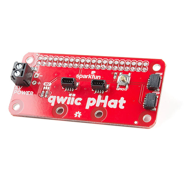
De Qwiic pHAT verbindt de I²C bus (GND, 3.3V, SDA, en SCL) op uw Raspberry Pi met een reeks van Qwiic connectoren op de HAT. Aangezien het Qwiic systeem het mogelijk maakt om borden met verschillende adressen door te lussen, kunt u zoveel sensoren stapelen als u wilt om een toren van sensorkracht te maken! De Qwiic pHAT V2.0 heeft vier Qwiic connect poorten (twee aan de zijkant en twee verticaal), allemaal op dezelfde I²C bus. We hebben ook gezorgd voor een eenvoudige 5V schroefaansluiting om borden te voeden die meer dan 3,3V nodig hebben en een druktoets (met de optie om de Pi uit te schakelen met een script). De montagegaten zijn gewijzigd op het bord, ze zijn nu zo geplaatst dat ze overeenkomen met de standaard Qwiic bordafmetingen van 1,0 'x 1,0'. Deze HAT is compatibel met elke Raspberry Pi die gebruik maakt van de standaard 2x20 GPIO header en met de NVIDIA Jetson Nano en Google Coral. Eigenschappen 4 x Qwiic Aansluitpoorten 1 x 5V schroefaansluiting 1 x Knop voor algemeen gebruik HAT-compatibele 40-pins socket
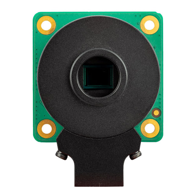
De Raspberry Pi High Quality Camera is een betaalbare hoogwaardige camera van Raspberry Pi. Hij heeft een resolutie van 12 megapixels en een 7,9 mm diagonale sensor voor indrukwekkende prestaties bij weinig licht. De M12 Mount variant is ontworpen om te werken met de meeste van de verwisselbare M12 lenzen, terwijl de CS Mount variant is ontworpen om te worden gebruikt met verwisselbare lenzen in zowel CS als C mount uitvoeringen (C mount lenzen vereisen het gebruik van de C-CS adapter die bij dit objectief wordt meegeleverd). Andere uitvoeringen van de lens kunnen worden aangepast met behulp van lensadapters van derden.De High Quality Camera is zeer geschikt voor industriële en consumententoepassingen, zoals beveiligingscamera's, die het hoogste niveau van visuele getrouwheid en/of integratie met gespecialiseerde optica vereisen. Hij is compatibel met alle modellen van Raspberry Pi vanaf Model B.Specificaties
Sensor
Sony IMX477R stacked, back-illuminated sensor
Resolutie
12,3 megapixels< / td>
Sensor formaat
7,9 mm sensor diagonaal
Pixel formaat td>
1,55 x 1,55 ?m
Output
RAW12/10/8, COMP8
Back focus lengte van de lens
2,6–11,8 mm (M12 Mount variant)12,5–22,4 mm (CS Mount variant)
Lens sensor formaat
1/2,3' (7,9 mm) of groter
IR cut filter
Geïntegreerd
Ribbon kabellengte
200 mm
Tripod houder
1/4'-20
Inbegrepen
1x Print met daarop een Sony IMX477 sensor
1x FPC kabel voor aansluiting op een Raspberry Pi computer
1x Gefreesde aluminium lenshouder met geïntegreerde statiefbevestiging
1x C naar CS Mount adapter
3x Lens borgringen
Niet inbegrepenM12 Mount Lens
The Mendocino Motor AR O-8 is a magnetically levitated, solar powered electric motor as a kit.
Light Becomes Movement
The solar-powered Mendocino motor seems to float in the air. At first glance, you can't see why the rotor is turning at all. This is the magic of the motor.
The Lorentz force is a very small electrical force. In a classroom setting, it is detected by a current swing in the magnetic field. With the Mendocino motor, we have succeeded in developing a beautiful application that uses this weak force for propulsion. Due to its concealed base magnet, the motor will fascinate technically inclined observers.
In bright sunlight, the motor can reach a speed of up to 1,000 rpm. More impressive, however, is that even the faint glow of an ample tea light (D = 6 cm with a flame height of about 2 cm) is sufficient to drive the motor. The motor is not yet an alternative source of energy, even though it looks tempting. Presumably, it will remain an attractive model until a resourceful mind disproves this assumption.
Dimensions
All solar cells 65 x 20 mm
Mirror diameter: 25 mm
Rotor weight: approx. 150 g
Model length: 160 mm
Model width: 85 mm
Frame height: approx. 85 mm
Frame material: black acrylic
Tube made of highly polished aluminum
Mirror color: silver
The Mendocino motor’s easy-to-follow instruction manual includes more than 70 illustrations. It describes a safe and practical approach to construction but also gives you the freedom to try your solutions.
Partly Pre-Assembled Kit
A portion of the kit comes pre-assembled. Bonding the borosilicate glass pane to the acrylic surface requires specialized knowledge and aids. We do not want to impose this on the hobbyist. For instance, the base magnet is attached to the aluminum tube.
As a hobbyist, you will need some know-how and appropriate tools: carpet knife, soldering iron and tin, hot glue, pliers, and a clamp or ferrule to fix the supplied assembly aid. A lot of fun is guaranteed!