The EC200U-EU C4-P01 development board features the EC200U-EU LTE Cat 1 wireless communication module, offering a maximum data rate of up to 10 Mbps for downlink and 5 Mbps for uplink. It supports multi-mode and multi-band communication, making it a cost-effective solution.
The board is designed in a compact and unified form factor, compatible with the Quectel multi-mode LTE Standard EC20-CE. It includes an onboard USB-C port, allowing for easy development with just a USB-C cable.
Additionally, the board is equipped with a 40-pin GPIO header that is compatible with most Raspberry Pi HATs.
Kenmerken
Equipped with EC200U-EU LTE Cat 1 wireless communication module, multi-mode & multi-band support
Onboard 40-Pin GPIO header, compatible with most Raspberry Pi HATs
5 LEDs for indicating module operating status
Supports TCP, UDP, PPP, NITZ, PING, FILE, MQTT, NTP, HTTP, HTTPS, SSL, FTP, FTPS, CMUX, MMS protocols, etc.
Supports GNSS positioning (GPS, GLONASS, BDS, Galileo, QZSS)
Onboard Nano SIM card slot and eSIM card slot, dual card single standby
Onboard MIPI connector for connecting MIPI screen and is fully compatible with Raspberry Pi peripherals
Onboard camera connector, supports customized SPI cameras with a maximum of 300,000 pixels
Provides tools such as QPYcom, Thonny IDE plugin, and VSCode plugin, etc. for easy learning and development
Comes with online development resources and manual (example in QuecPython)
Specificaties
Applicable Regions
Europe, Middle East, Africa, Australia, New Zealand, Brazil
LTE-FDD
B1, B3, B5, B7, B8, B20, B28
LTE-TDD
B38, B40, B41
GSM / GPRS / EDGE
GSM: B2, B3, B5, B8
GNSS
GPS, GLONASS, BDS, Galileo, QZSS
Bluetooth
Bluetooth 4.2 (BR/EDR)
Wi-Fi Scan
2.4 GHz 11b (Rx)
CAT 1
LTE-FDD: DL 10 Mbps; UL 5 Mbps
LTE-TDD: DL 8.96 Mbps; UL 3.1 Mbps
GSM / GPRS / EDGE
GSM: DL 85.6 Kbps; UL 85.6 Kbps
USB-C Port
Supports AT commands testing, GNSS positioning, firmware upgrading, etc.
Communication Protocol
TCP, UDP, PPP, NITZ, PING, FILE, MQTT, NTP, HTTP, HTTPS, SSL, FTP, FTPS, CMUX, MMS
SIM Card
Nano SIM and eSIM, dual card single standby
Indicator
P01: Module Pin 1, default as EC200A-XX PWM0
P05: Module Pin 5, NET_MODE indicator
SCK1: SIM1 detection indicator, lights up when SIM1 card is inserted
SCK2: SIM2 detection indicator, lights up when SIM2 card is inserted
PWR: Power indicator
Buttons
PWK: Power ON/OFF
RST: Reset
BOOT: Forcing into firmware burning mode
USB ON/OFF: USB power consumption detection switch
Antenna Connectors
LTE main antenna + DIV / WiFi (scanning only) / Bluetooth antenna + GNSS antenna
Operating Temperature
−30~+75°C
Storage Temperature
−45~+90°C
Downloads
Wiki
Quectel Resources
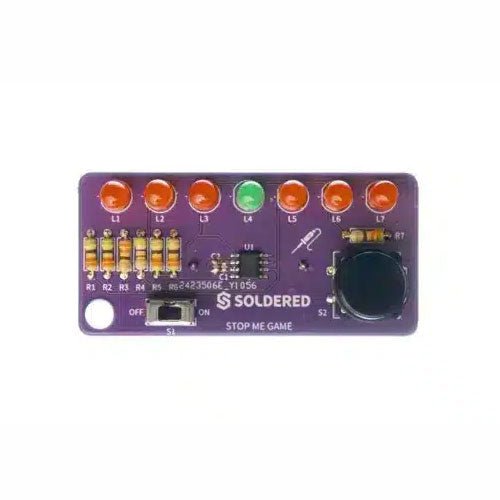
If you are looking for a simple way to learn soldering, or just want to make a small gadget that you can carry, this set is a great opportunity. Stop me game is an educational kit which teaches you how to solder, and in the end, you get to have your own small game. The LEDs go up and down, and your goal is to press the button as soon as the green LED turns on. With every correct answer, the game gets a bit harder – the time you have to press the button shortens. How many correct answers can you get?
It’s based on ATtiny404 microcontroller, programmed in Arduino. At its back, you’ll find CR2032 battery which makes the kit portable. There’s keychain holder as well. Soldering process is easy enough based on the mark on the PCB.
Included
1x PCB
1x ATtiny404 microcontroller
7x LEDs
1x Pushbutton
1x Switch
7x Resistors (330 ohm)
1x CR2032 battery holder
1x Battery CR2032
1x Keychain holder
Maker Line is een lijnsensor met 5 x IR sensoren array die in staat is om lijnen te volgen van 13 mm tot 30 mm breedte.De sensor calibratie is ook vereenvoudigd. Het is niet nodig om de potentiometer voor elke IR sensor aan te passen. U hoeft alleen maar de calibrate knop gedurende 2 seconden in te drukken om de calibratie modus te openen. Daarna moet u de sensoren over de lijn laten vegen, nogmaals op de knop drukken en u bent klaar om te gaan.De kalibratiegegevens worden opgeslagen in EEPROM en deze blijven intact, zelfs als de sensor is uitgeschakeld. Kalibratie hoeft dus maar één keer te worden uitgevoerd, tenzij de sensorhoogte, lijnkleur of achtergrondkleur is veranderd.Maker Line ondersteunt ook dubbele uitgangen: 5 x digitale uitgangen voor de status van elke sensor onafhankelijk, wat vergelijkbaar is met conventionele IR-sensor, maar u krijgt het voordeel van eenvoudige kalibratie, en ook een analoge uitgang, waar de spanning de lijnpositie vertegenwoordigt. De analoge uitgang biedt ook een hogere resolutie in vergelijking met afzonderlijke digitale uitgangen. Dit is vooral nuttig wanneer een hoge nauwkeurigheid vereist is bij het bouwen van een lijnvolgende robot met PID regeling.Features
Bedrijfsspanning: DC 3,3 V en 5 V compatibel (met omgekeerde polariteitsbeveiliging)
Aanbevolen lijndikte: 13 mm tot 30 mm
Selecteerbare lijnkleur (licht of donker)
Sensor afstand (hoogte): 4 mm tot 40 mm (Vcc = 5 V, zwarte lijn op wit oppervlak)
Sensor Vernieuwingsfrequentie: 200 Hz
Eenvoudig kalibratieproces
Dubbele uitgangstypen: 5 x digitale uitgangen vertegenwoordigen elke IR-sensor staat, 1 x analoge uitgang vertegenwoordigt lijn positie.
Ondersteunt een breed scala aan controllers, zoals Arduino, Raspberry Pi etc.
Documentatie
Datasheet
Tutorial: Een goedkope lijnvolgende robot bouwen
Features NDIR CO2-sensortechnologie: ingebed in Sensirion SCD30 Multi-functie: Integreert temperatuur- en vochtigheidssensor op dezelfde sensormodule Hoge precisie en grote meetnauwkeurigheid: ±(30 ppm + 3%) tussen 400 ppm en 10000 ppm Superieure stabiliteit: Detectie met twee kanalen Eenvoudige projectbediening: Digitale interface I²C, Breadboard-vriendelijk, Grove-compatibel Beste prestatie-prijs verhouding Toepassingsideeën Luchtzuiveraar Milieubewaking Milieubewakingssysteem voor planten Arduino weerstation
This camera adopts binocular structured light 3D imaging technology to obtain depth images and realize the function of depth information modeling. It is equipped with a dedicated depth computing chip and is specially optimized for robot obstacle avoidance.The camera is compact in size, easy to integrate, with USB2.0 standard output interface, providing users with a high degree of flexibility. It can be adapted to complex environments such as all-black environment, indoors with strong light or weak light, backlight or smooth light, even semi-outdoors, which has a wide range of applications.Features
Offers 1280 x 920 high-resolution image output
Uses the binocular structured light 3D imaging technology
Fearless ambient light interference
Deep calculation processors use high-performance dedicated chips
USB2.0 standard output interface
Specifications
Detection distance: 20-250 cm
Accuracy Error: <1.5 cm
Resolution: 1280 x 920 Pixel
HFOV: 78 ±3°
VFOV: 60 ±3°
Power: 1.5 W
Active Light Source: Spectrum: 830-850 nm | Power: <1.5 W
Dust-proof and Waterproof: IP65
ESD: Contact Discharge: ±8 KV | Antiaircraft: ±12 KV
Interface: USB2.0
Operating Temperature: -10~50 °C
Operating Humidity: 0~80 RH
Storage Temperature: -20~80 °C
Weight: 96 g
Downloads
Datasheet
User Manual
Development Manual
SDK
Tool
ROS
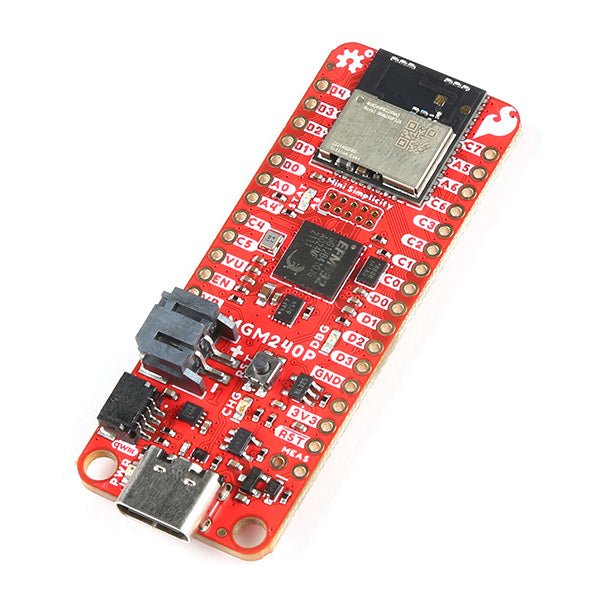
The SparkFun Thing Plus Matter is the first easily accessible board of its kind that combines Matter and SparkFun’s Qwiic ecosystem for agile development and prototyping of Matter-based IoT devices. The MGM240P wireless module from Silicon Labs provides secure connectivity for both 802.15.4 with Mesh communication (Thread) and Bluetooth Low Energy 5.3 protocols. The module comes ready for integration into Silicon Labs' Matter IoT protocol for home automation.
What is Matter? Simply put, Matter allows for consistent operation between smart home devices and IoT platforms without an Internet connection, even from different providers. In doing so, Matter is able to communicate between major IoT ecosystems in order to create a single wireless protocol that is easy, reliable, and secure to use.
The Thing Plus Matter (MGM240P) includes Qwiic and LiPo battery connectors, and multiple GPIO pins capable of complete multiplexing through software. The board also features the MCP73831 single-cell LiPo charger as well as the MAX17048 fuel gauge to charge and monitor a connected battery. Lastly, a µSD card slot for any external memory needs is integrated.
The MGM240P wireless module is built around the EFR32MG24 Wireless SoC with a 32-bit ARM Cortext-M33 core processor running at 39 MHz with 1536 kb Flash memory and 256 kb RAM. The MGM240P works with common 802.15.4 wireless protocols (Matter, ZigBee, and OpenThread) as well as Bluetooth Low Energy 5.3. The MGM240P supports Silicon Labs' Secure Vault for Thread applications.
Specifications
MGM240P Wireless Module
Built around the EFR32MG24 Wireless SoC
32-bit ARM-M33 Core Processor (@ 39 MHz)
1536 kB Flash Memory
256 kB RAM
Supports Multiple 802.15.4 Wireless Protocols (ZigBee and OpenThread)
Bluetooth Low Energy 5.3
Matter-ready
Secure Vault Support
Built-in Antenna
Thing Plus Form-Factor (Feather-compatible):
Dimensions: 5.8 x 2.3 cm (2.30 x 0.9")
2 Mounting Holes:
4-40 screw compatible
21 GPIO PTH Breakouts
All pins have complete multiplexing capability through software
SPI, I²C and UART interfaces mapped by default to labeled pins
13 GPIO (6 labeled as Analog, 7 labeled for GPIO)
All function as either GPIO or Analog
Built-in-Digital to Analog Converter (DAC)
USB-C Connector
2-Pin JST LiPo Battery Connector for a LiPo Battery (not included)
4-Pin JST Qwiic Connector
MC73831 Single-Cell LiPo Charger
Configurable charge rate (500 mA Default, 100 mA Alternate)
MAX17048 Single-Cell LiPo Fuel Gauge
µSD Card Slot
Low Power Consumption (15 µA when MGM240P is in Low Power Mode)
LEDs:
PWR – Red Power LED
CHG – Yellow battery charging status LED
STAT – Blue status LED
Reset Button:
Physical push-button
Reset signal can be tied to A0 to enable use as a peripheral device
Downloads
Schematic
Eagle Files
Board Dimensions
Hookup Guide
Datasheet (MGM240P)
Fritzing Part
Thing+ Comparison Guide
Qwiic Info Page
GitHub Hardware Repo
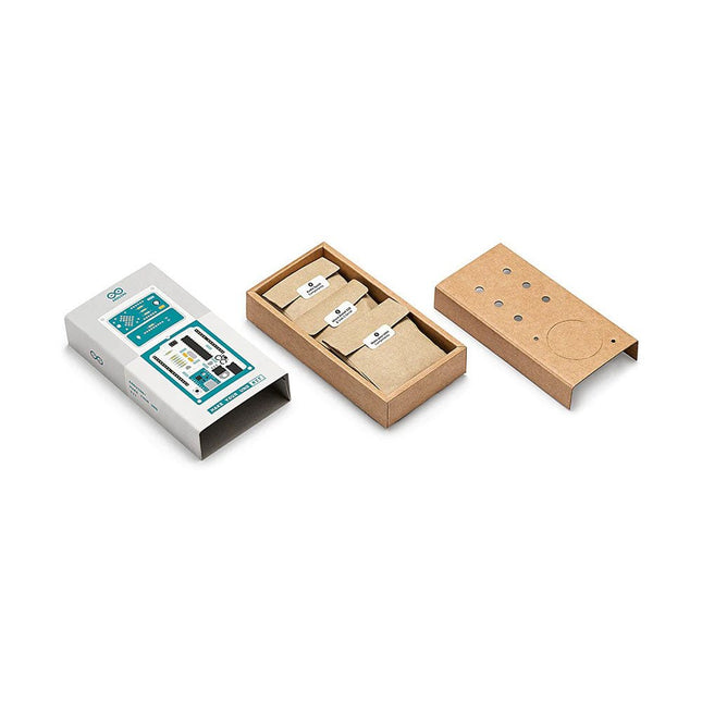
Doe basiskennis van elektronica op door zelf handmatig uw Arduino Uno in elkaar te zetten, raak vertrouwd met solderen door eigenhandig elk onderdeel te monteren, en laat vervolgens uw creativiteit de vrije loop met de enige kit waarmee u ook meteen een synthesizer kan bouwen! De Arduino Make-Your-Uno kit is echt de beste kit om te leren solderen. En als u klaar bent kunt u met deze bundel ook een synthesizer bouwen en muziek maken. Een kit met alle componenten om uw eigen Arduino Uno mét audio synthesizerkaart te bouwen. De Make-Your-Uno kit wordt geleverd met een complete set instructies, beschikbaar op een speciale website. Deze biedt videomateriaal, een interactieve 3D-viewer voor het volgen van gedetailleerde instructies, en hoe u uw board kunt programmeren zodra deze is afgebouwd. Deze kit bevat: Arduino Make-Your-Uno 1x Make-Your-Uno PCB 1x USB C serial adapter board 7x weerstanden 1k Ohm 2x weerstanden 10k Ohm 2x weerstanden 1M Ohm 1x diode (1N4007) 1x 16 MHz kristal 4x gele LED's 1x groene LED 1x drukknop 1x MOSFET 1x LDO (3,3 V) 1x LDO (5 V) 3x keramische condensatoren (22pF) 3x elektrolytische condensatoren (47uF) 7x polyester condensatoren (100nF) 1x socket voor ATMega 328p 2x I/O connectoren 1x connector header 6 pins 1x barrel jack connector 1x ATmega 328p microcontroller Arduino Audio Synth 1x Audio Synth PCB 1x weerstand 100k Ohm 1x weerstand 10 Ohm 1x audio versterker (LM386) 1x keramische condensator (47nF) 1x elektrolytische condensator (47uF) 1x elektrolytische condensator (220uF) 1x polyester condensator (100nF) 4x connectoren pin header 6x potentiometer 10k Ohm met kunststof knoppen Reserveonderdelen 2x elektrolytische condensatoren (47uF) 2x polyester condensatoren (100nF) 2x keramische condensatoren (22pF) 1x drukknop 1x gele LED 1x groene LED Mechanische onderdelen 5x afstandhouders 12 mm 11x afstandhouders 6 mm 5x schroefmoeren 2x schroeven 12 mm
The Intelligent Digital Thermostat Temperature Controller is a small switch controller (77x51mm) which allows you to create your own thermostat. With its NTC Sensor and its LED displays, you are able to switch up to 10A 220V depending on the measured temperature.
Grove 3-Axis Digitale Versnellingsmeter (LIS3DHTR) is een goedkope 3-Axis versnellingsmeter in een bundel van Grove producten. Het is gebaseerd op de LIS3DHTR chip die meerdere bereiken en interfaces selectie biedt. Het is niet te geloven dat zo'n kleine 3 assige versnellingsopnemer I²C, SPI en ADC GPIO interfaces kan ondersteunen, wat betekent dat u elke manier kunt kiezen om verbinding te maken met uw ontwikkelbord. Bovendien kan deze versnellingsmeter ook de omringende temperatuur monitoren om de daardoor veroorzaakte fout af te stellen. Features Metingsbereik: ±2g, ±4g, ±8g, ±16g, selectie van meerdere bereiken. Meervoudige interfaces optie: Grove I²C interface, SPI interface, ADC interface. Temperatuur instelbaar: in staat om aan te passen en af te stemmen de fout veroorzaakt door temperatuur. 3/5V voeding Specificaties Voeding 3/5V Interfaces IC/SPI/GPIO ADC I²C adres Standaard 0x19, kan worden gewijzigd in 0x18 wanneer SDO Pin wordt verbonden met GND ADC GPIO stroomingang 0-3.3V Onderbreking Een onderbrekingsspeld gereserveerd SPI-Modus instellen Sluit de CS-Pin aan op GND Inclusief 1x Grove 3-Axis Digitale Versnellingsmeter (LIS3DHTR) 1x Grove kabel Downloads LIS3DHTR Datasheet Hardwareschema Arduino-bibliotheek
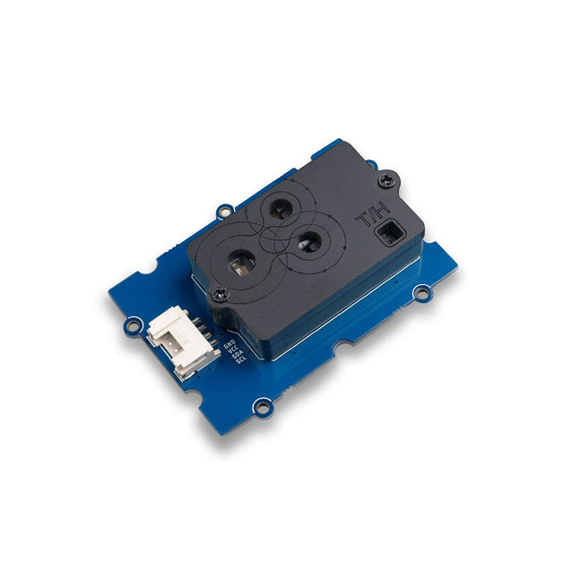
This module has an ultrasonic transmitter and an ultrasonic receiver so you can consider it as an ultrasonic transceiver. Familiar with sonar, when the 40 kHz ultrasonic wave generated by the transmitter encounters the object, the sound wave will be emitted back, and the receiver can receive the reflected ultrasonic wave. It is only necessary to calculate the time from the transmission to the reception, and then multiply the speed of the sound in the air (340 m/s) to calculate the distance from the sensor to the object. Features 3.3V / 5V compatible, wide voltage level: 3.2V~5.2V Only 3 pins are needed, save I/O resources Wide measurement range: 3cm ~ 350cm Plug and play with Grove connector Applications Distance measurement Ultrasonic detector Proximity alarm Smart car Technical Specifications Dimensions 50 mm x 25 mm x 16 mm Weight 17 g Battery Exclude Measuring range 3 cm - 350 cm Operating voltage DC 3.2 V ~ 5.2 V Operating current 8 mA Ultrasonic frequency 40 kHz Connector 1 x Grove Output PWM
De ThingPulse Pendrive S3 is een ESP32-S3-apparaat met USB-C-stekker, WS2812B RGB-LED en 128 MB Flash. Met behulp van TinyUSB kan de ESP32-S3 zich voordoen als vele USB-apparaten, zoals:
USB-geheugenstick
USB-toetsenbord
USB-muis
Audioapparaat
Videoapparaat
Netwerkapparaat
Toepassingen
Als BadUSB-apparaat met SuperWiFiDuck kan het KeyStroke-injecties uitvoeren
Als WiFiDisk kan hij door elke gewone computer worden aangekoppeld, zoals een geheugenstick, en kan hij de bestanden op de schijf synchroniseren met de cloud
Als WiFiDongle kan het een extra WiFi-netwerkapparaat aan elke computer/telefoon toevoegen
Inbegrepen
ESP32-S3 printplaat met
WS2812B RGB-LED
Capacitieve aanraakknop (veer)
Plastic behuizing van USB-drive
Downloads
CircuitPython
Wilt u een UV-detector maken om de UV-index te weten wanneer u zich onder de zon bevindt? Grove Sunlight Sensor is een meerkanaals digitale lichtsensor, die zowel UV-licht, zichtbaar licht als infrarood licht kan detecteren.Dit apparaat is gebaseerd op de SI1151, een nieuwe sensor van SiLabs. De Si1151 is een laag-vermogen, op reflectie gebaseerde, infrarode nabijheids-, UV-index- en omgevingslichtsensor met I²C digitale interface en programmeerbare-gebeurtenis interrupt uitgang. Dit apparaat biedt uitstekende prestaties onder een breed dynamisch bereik en een verscheidenheid van lichtbronnen, waaronder direct zonlicht.Grove Sunlight Sensor bevat een on-board Grove connector, die u helpt om het gemakkelijk aan te sluiten op uw Arduino. U kunt dit apparaat gebruiken voor het maken van een aantal projecten die het licht moeten detecteren, zoals een eenvoudige UV-detector voor uw Raspberry Pi weerstation, of een slim irrigatiesysteem met behulp van Arduino als je nodig hebt om het zichtbare spectrum te monitoren.Features
Multi-kanaals digitale lichtsensor: kan UV-licht, zichtbaar licht en infrarood licht detecteren
Breed spectrum detectiebereik: 280-950 nm
Gemakkelijk in gebruik: I²C-interface (7-bit), compatibel met Grove-poort, gewoon plug-and-play
Programmeerbare configuratie: Veelzijdig voor verschillende toepassingen
3,3/5 V voeding, geschikt voor vele microcontrollers en SBC's
Toepassingen
Lichtdetectie
Slimme irrigatiesysteem
DIY weerstation
Inbegrepen
1x Grove Zonlicht Sensor
1x Grove kabel
Downloads
Schema in PDF
Schema in Eagle-bestand
Si1145 Datasheet
GitHub Repositoriy voor Grove Sunlight Sensor
Spectrum
Lumen (eenheid)
Ultraviolet index
Features Pitch spacing is 2.54 mm (1 to 36 contacts per row) with vertical orientation Number of contacts: 40 Number of rows: 2 Gender: receptacle Contact termination type: Through hole Contact Plating: Tin plated contacts High operating temperature range of -55°C to 105°C for matte tin plated contacts Contact material is phosphor bronze Black glass filled polyester insulator material Tiger Buy contact system Complies with UL E111594 and CSA 090871_0_000 standards
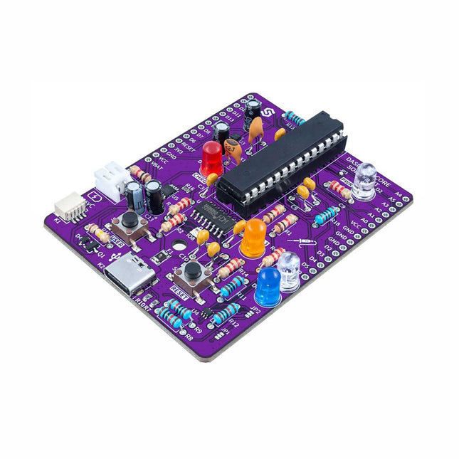
If you’re looking for a simple way to start soldering or just want to make your own Dasduino, this soldering set is a great opportunity. "Make your own Dasduino CORE" is an educational set for learning the skill of soldering, with which you end up with a functional microcontroller board. As with the other SMD versions of the Dasduino CORE boards we offer, the possibilities are endless.
It is based on the ATmega328P microcontroller, and all SMD components are already soldered on the board. The set also includes a THT socket for the microcontroller, which simplifies the replacement of the microcontroller should it ever become necessary.
Included
1x PCB
7x Capacitors (100nF)
4x Capacitors (2.2uF)
2x Capacitors (22pF)
5x Resistors (2.2 kOhm)
5x Resistors (10 kOhm)
3x Resistors (1 kOhm)
1x Resistor (100 kOhm)
1x Resistor (100 ohm)
1x JST battery connector
1x LED (purple)
1x LED (white)
1x LED (blue)
1x LED (red)
1x LED (orange)
1x Socket for ATmega328P
1x ATmega328P microcontroller
Features Ondersteunt NMEA en U-Blox 6 protocollen. Laag stroomverbruik Baudrates configureerbaar Grove UART-interface Specificaties Afmetingen 40 mm x 20 mm x 13 mm Update snelheid 1 Hz, max 10 Hz Baud Rate 9.600 - 115.200 Invoer Voltage 3,3 V / 5 V Navigatiegevoeligheid -160dBm Voedingsvereisten 3.3/5V Aantal Kanalen 22 tracking, 66 kanalen Tijd tot eerste start Koude start: 13sWarme start: 1-2swarme start: < 1s Antennels Antenne inbegrepen Nauwkeurigheid 2,5m GPS Horizontale Positie Nauwkeurigheid
The matte-black circuit board is extra thick and has subtle white markings, including an alphanumeric grid and PIN labels. The wiring pattern — that of classic breadboards — is easy to see by looking at the exposed traces on the bottom of the board.
The kit comes complete with the 'Integrated Circuit Leg' stand and 8 colour-coded thumbscrew terminal posts. Using the terminal posts and solder points, you can hook up to your 'IC' with bare wires, lugs, alligator clips, and/or solder joints. Connections to the 8 terminal posts are through the three-position strips on the PCB; each is labelled with the corresponding PIN.
Kenmerken
Anodized aluminium stand
8-32 size press-fit threaded inserts (8 pieces) pre-installed in the protoboard
All materials (including the circuit board and stand) are RoHS compliant (lead-free)
Tri lobular thread forming screws (6 pieces, black, 6-32 thread size) and spacers for mounting the stand.
Dimensions: 13.25 x 8.06 x 2.54 mm
Dimensions assembled: 13.25 x 9.9 x 4.3 cm
Grove LED Bar is comprised of a 10 segment LED gauge bar and an MY9221 LED controlling chip. It can be used as a indicator for remaining battery life, voltage, water level, music volume or other values that require a gradient display.There are 10 LED bars in the LED bar graph: one red, one yellow, one light green, and the rest green. Demo code is available to get you up and running quickly. It lights up the LEDs sequentially from red to green, so the entire bar graph is lit up in the end. Want to go further? Go ahead and code your own effect!Features
Each LED segment can be controlled individually via code
Grove module
Plug-and-play
Can be cascaded for a larger display
Flexible power option, supports 3-5.5 DC
Available demo code
Dimensions: 40 x 20 x 18 mm
Included
1x Grove LED Bar v2.0
1x Grove Cable
Downloads
Grove LED Bar Eagle File
Grove LED Bar Library
MY9221 Datasheet
Suli-compatible Library
GitHub repository for LED Bar
10 Segment LED Gauge Bar
De Ynvisible Segment E-Paper Displays zijn dun & flexibel, zonlicht leesbaar, zeer eenvoudig te bedienen, en dat ze de meest energie-efficiënte display technologie op de markt voor de meeste toepassingen. Ga vandaag nog aan de slag! Evalueer de ultra-low-power, dunne en flexibele Segment E-Paper Displays. De kit bevat display-ontwerpen en bevat zowel een handmatige display-driver als een display-driver met I²C-interface. Display parameters White Reflectance 40% Contrastverhouding (Yb/Yd) 1:3 Afhankelijkheid van de hoek Nee, lambertiaan Dikte 300 µm Grafische opmaak Segmenten Afmetingen segmenten 1-100 mm Responstijd 100-1000 ms Power parameters Aandrijfspanning 1,5 V Aandrijfmethode Directe aandrijving Energieverbruik 1 mJ/cm^2 Pulsenergie 0,25 mJ/cm^2 Beeldbehoud zonder stroom 1-5 minuten Bedrijfsomstandigheden -20°C - +60°C Activeringen/cycli 1.000.000 Inbegrepen
Onzichtbare Segment Displays (Gesegmenteerde e-paper displays met verschillende lay-outs, vormen en symbolen, geschikt voor testen en evaluatie.) 3 eencijferig display 1 dubbelcijferig display 5 displays met één segment/icoon 4 voortgangsbalken (7-segment en 3-segment)
Handmatige display-klikker (handmatige display-controller voor aan/uit-bediening)
Display-driver en softwarebibliotheek (Speciale display-driver met I²C-communicatie-interface. Compatibel met Arduino en andere gebruiksvriendelijke ontwikkelborden)
Flexibele display-adapter (Voor gemakkelijke aansluiting van flexibele displays op een plastic ondergrond op harde elektronica (zoals ontwikkelborden), met behulp van een FFC/FPC-connector.) Downloads Datasheet Gids & instructies
De MicroMod DIY Carrier Kit bevat vijf M.2 connectoren (4.2mm hoogte), schroeven en standoffs zodat u over alle speciale onderdelen beschikt die u nodig heeft om uw eigen carrier-board te maken. MicroMod gebruikt de standaard M.2 connector. Dit is dezelfde connector als die op moderne moederborden en laptops. Er zijn verschillende plaatsen voor de plastic 'key' op de M.2 connector om te voorkomen dat een gebruiker er een niet-compatibel apparaat insteekt. De MicroMod standaard gebruikt de 'E'-key en wijkt van de M.2 standaard af doordat de montageschroef 4 mm naar de zijkant is verplaats. De 'E'-key is vrij gangbaar, zodat een gebruiker een M.2-compatibele Wifi-module zou kunnen plaatsen. Maar omdat de schroefbevestiging niet uitgelijnd is, zou de gebruiker een niet-compatibel apparaat niet kunnen vastzetten op een MicroMod-carrier. Eigenschappen 5x kruiskopschroef M2.5 x 3 mm 5x SMD Reflow Compatible Standoffs M2.5 x 2,5mm 5x M.2 MicroMod Connector Key: E Hoogte: 4.2 mm Aantal pennen: 67 Pitch: 0.5 mm
De Pico Cube is een 4x4x4 led kubus HAT voor Raspberry Pi Pico met 5 VDC bedrijfsspanning. De Pico Cube, een monochromatisch Rood met 64 leds, leert u op een leuke manier programmeren. Hij is ontworpen om lichtgevende bewerkingen te tonen met een laag energieverbruik, heeft een robuust ontwerp en is eenvoudig te installeren, waardoor mensen / kinderen / gebruikers de effecten op leds met een verschillend kleurenpatroon leren kennen door software en hardware, zoals de Raspberry Pi Pico, te combineren. Kenmerken Standaard 40-pins Raspberry Pi Pico header GPIO-gebaseerde communicatie 64 high-intensity monochromatische leds Toegang tot individuele leds Toegang tot elke laag Specificaties Bedrijfsspanning: 5 V Kleur: rood Communicatie: GPIO Leds: 64 Inbegrepen 1x Pico Cube basis PCB 4x PCB lagen 8x PCB pilaren 2x berg strips (1 x 20), male 2x berg strips (1 x 20), female 70 leds Opmerking: Raspberry Pi Pico is niet inbegrepen. Downloads GitHub Wiki
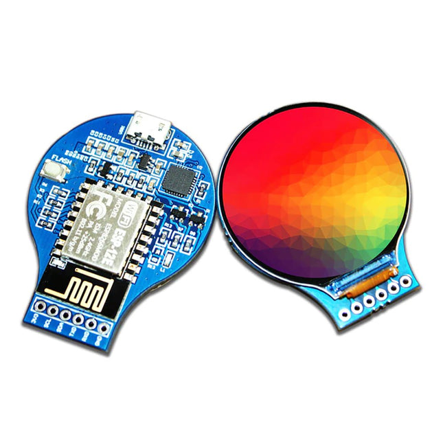
Het Waveshare ESP32-S3 1,47" Display Development Board is een microcontrollerplatform met 2,4 GHz WiFi, Bluetooth BLE 5, Flash met hoge capaciteit en PSRAM. Het LCD-scherm ondersteunt soepele GUI-ontwikkeling met LVGL, terwijl meerdere randapparatuur interfaces maken het ideaal voor snelle prototyping van HMI en andere op ESP32-S3 gebaseerde toepassingen.
Kenmerken
Processor: Uitgerust met een krachtige Xtensa 32-bit LX7 dual-core processor, die werkt op maximaal 240 MHz.
Connectiviteit: Ondersteunt 2,4 GHz Wi-Fi (802.11 b/g/n) en Bluetooth 5 (LE) met een ingebouwde antenne.
Geheugen: Ingebouwd 512 KB SRAM, 384 KB ROM, 16 MB Flash en 8 MB PSRAM voor voldoende opslag en prestaties.
Scherm: Beschikt over een 1,47-inch LCD-scherm met een resolutie van 172 x 320 en 262K kleuren, ideaal voor GUI-toepassingen.
Interfaces: Past meerdere IO-interfaces aan en integreert een full-speed USB-poort voor veelzijdige connectiviteit.
Opslag: Bevat een TF-kaartsleuf voor externe opslag van foto's en bestanden.
Energie-efficiëntie: Ondersteunt nauwkeurige bediening met flexibele klokinstellingen en meerdere energiemodi, waardoor een laag energieverbruik in alle scenario's mogelijk is.
Verlichting: Ingebouwde RGB-LED met een helder acryl sandwichpaneel voor aanpasbare en stijlvolle lichteffecten.
Inbegrepen
1x ESP32-S3 1,47" Display Development Board (ESP32-S3-LCD-1.47)
1x Header (zwart)
Downloads
Wiki
This IPS 7.9-inch HDMI touch display with 400 x 1280 resolution, 170° wide viewing angle and built-in ferrite Hi-Fi speaker can be used as a secondary screen for chassis and also supports Raspberry Pi and Jetson Nano.
Features
7.9-inch IPS display with a hardware resolution of 400 x 1280.
Zinc alloy case, toughened glass panel with up to 6H hardness.
When working as a computer monitor, it supports Windows without a driver.
When working with Raspberry Pi, it supports Raspberry Pi OS / Ubuntu / Kali and Retropie, driver-free.
When working with Jetson Nano, it supports Ubuntu, driver-free.
Support backlight control for power saving.
Support 5-point capacitive touch control.
Specifications
Display size
7.9"
Viewing angle
170°
Resolution
400 x 1280 pixels
Display area
191.08 x 60.40 mm
IPS version solor gamut
62% NTSC
Max brightness
550 cd/m²
Backlight adjustment
Adjusted by the key/HID software
Contrast
900:1
Color depth
16.7M
Refresh rate
60 Hz
Power port
USB-C
Display port
HDMI interface
Dimensions
211 x 73 x 20 mm
Included
1x 7.9-inch Side Monitor
1x HDMI to Micro HDMI adapter
1x USB Type-A to Type-C cable (1 m)
1x HDMI flat cable (1 m)
2x Nonskid rubber feet
Downloads
Wiki
Features Bodemvochtsensor gebaseerd op bodemweerstandsmeting bestaat uit twee sondes die de stroom door de bodem laten lopen Gemakkelijk in gebruik en kosteneffectief Grove compatibele interface (u-blox versie) Specificaties Afmetingen: 60 x 20 x 6,35 mm
Gewicht: 10 g
Batterij: Exclusief
Bedrijfsspanning: 3,3 V ~ 5 V
Bedrijfsstroom: 35 mA
Sensor Uitgangswaarde in droge grond: 0 ~ 300
Sensoruitgangswaarde in vochtige grond: 300 ~ 700
Sensor Uitgangswaarde in water: 700 ~ 950
Hier vind je allerlei onderdelen, componenten en accessoires die je nodig hebt in verschillende projecten, te beginnen met eenvoudige draden, sensoren en displays tot en met reeds voorgemonteerde modules en kits.