Producten
-

OWON OWON HDS120 (2-in-1) True RMS Multimeter & Oscilloscoop
De OWON HDS120 is een nauwkeurige 4½-cijferige True RMS multimeter (20.000 counts), ideaal voor professionals, makers en studenten. Hij biedt intelligente sondedetectie, automatische golfvormmetingen (Vmax, Vmin, Vp-p, Vavg, Vrms en frequentie) en een volledig uitgeruste handheld oscilloscoop (1 MHz). Kenmerken Multifunctioneel meetinstrument: 4½-cijferige multimeter + oscilloscoop Automatische golfvormmetingen: Inclusief Vmax, Vmin, Vp-p, Vavg, Vrms en frequentie. Gebruiksvriendelijk ontwerp: Duidelijk gelabelde toetsen voor eenvoudige bediening en langere levensduur van het apparaat. Intelligente sondedetectie: Schakelt automatisch tussen meetfuncties op basis van de sonde-inbreng, waardoor schade aan het instrument door onjuiste bediening effectief wordt voorkomen. Efficiënt energiebeheer: Aangedreven door 18650 lithiumbatterijen, voor een langere gebruiksduur en verbeterde betrouwbaarheid voor uitgebreide meettaken. Veilige hoogspanningsmeting: Voldoet aan de CAT Ⅲ 1000 V-normen, waardoor veilige en directe meting van hoogspanning mogelijk is. golfvormen tot 1000 V, waardoor de toepassingsmogelijkheden worden uitgebreid. High-Definition Display: beschikt over een 2,8-inch IPS-scherm met een brede kijkhoek, wat zorgt voor een duidelijke leesbaarheid vanuit elk perspectief. Adaptive Environmental Display: Hoge helderheid en contrastrijke dual-theme weergavemodi bieden optimale zichtbaarheid onder heldere en zwakke lichtomstandigheden, wat de algehele bruikbaarheid verbetert. Multimeter Specificaties Meetbereik Nauwkeurigheid DC-spanning (V) 20.000mV / 200.00mV / 2.0000V / 20.000V / 200.00V / 1000.0V ±(0.1%+5dig) AC-spanning (V) 20.000mV / 200.00mV / 6.0000V / 60.000V / 600.00V / 750.00V ±(0.6%+10dig) DC-stroom (A) 200.00uA / 2000.0uA / 20.000mA / 200.00mA / 2.0000A / 10.000A ±(0.5%+10dig) AC-stroom (A) 200.00uA / 2000.0uA / 20.000mA / 200.00mA / 2.0000A / 10.000A ±(0.8%+10dig) Weerstand (Ω) 200.00Ω / 2.0000kΩ / 20.000kΩ / 200.00KΩ / 2.0000MΩ / 20.000MΩ / 100.00MΩ ±(0.3%+5dig) Capaciteit (F) 2.000nF / 20.00nF / 200.0nF / 2.000μF / 20.00μF / 200.0μF / 2.000mF / 20.00mF ±(3.0%+10dig) Frequentie (Hz) 200.00Hz / 2.0000kHz / 20.000kHz / 200.00kHz / 2.0000MHz / 20.000MHz ±(0.1%+5dig) Inschakelduur 0.1%~99.9% (typische waarde: Vrms=1V, f=100Hz) ±(1.2%+3dig) 0.1%~99.9% (≥1kHz) ±(2.5%+10dig) Diode 3.0000V ±(1.0%+10dig) On-Off 1000.0Ω Display 20000 Oscilloscoop Specificaties Analoge bandbreedte 1 MHz (alleen ACV-schaal) Kanaal 1 Tijdbasisbereik 2,5us~10s/grid Verticaal spanningsgevoeligheidsbereik 30 mV~500 V/grid Verticale amplitudenauwkeurigheid ±(5% + 0,2div) Maximale spanningslimiet 1000 V DC+AC piek waarde Triggermodus Auto/Normal/Single Automatisch instellen Tijdbasis/Verticale amplitude/Triggerwaarde Maximale sample 5,0 MSa/s Ingangsimpedantie ≈10 MΩ Tijdbasisnauwkeurigheid ±(0,01% + 0,1div) Stroom verticaal gevoeligheidsbereik 100 μA~5 A/grid Meetfunctie Vmax, Vmin, Vp-p, Vavg, Vrms, Hz Maximale stroomlimiet 15 A DC+AC piekwaarde Trigger edge Rise edge/Fall edge Algemene Specificaties Display 2,8" LCD (320 x 240) Indicatie voor lege batterij Ja Achtergrondverlichting Ja Slaapstand Ja Ingangsbeveiliging Ja Relatieve meting Ja Ingangsimpedantie ≥10 MΩ Batterij 18650 Lithium Veiligheidsnaleving CAT III 1000V Afmetingen 93 x 41,5 x 188 mm Gewicht 0,35 kg Inbegrepen 1x OWON HDS120 multimeter & oscilloscoop 2x Multimeterkabels 1x USB-kabel 1x Opbergtas 1x Manual Downloads Datasheet Manual
€ 59,00
-

OWON OWON HDS160 (2-in-1) True RMS Multimeter & Oscilloscoop
De OWON HDS160 is een nauwkeurige 4½-cijferige True RMS multimeter (60.000 counts), ideaal voor professionals, makers en studenten. Hij biedt intelligente sondedetectie, automatische golfvormmetingen (Vmax, Vmin, Vp-p, Vavg, Vrms en frequentie) en een volledig uitgeruste handheld oscilloscoop (1 MHz). Kenmerken Multifunctioneel meetinstrument: 4½-cijferige multimeter + oscilloscoop Automatische golfvormmetingen: Inclusief Vmax, Vmin, Vp-p, Vavg, Vrms en frequentie. Gebruiksvriendelijk ontwerp: Duidelijk gelabelde toetsen voor eenvoudige bediening en langere levensduur van het apparaat. Intelligente sondedetectie: Schakelt automatisch tussen meetfuncties op basis van de sonde-inbreng, waardoor schade aan het instrument door onjuiste bediening effectief wordt voorkomen. Efficiënt energiebeheer: Aangedreven door 18650 lithiumbatterijen, voor een langere gebruiksduur en verbeterde betrouwbaarheid voor uitgebreide meettaken. Veilige hoogspanningsmeting: Voldoet aan de CAT Ⅲ 1000 V-normen, waardoor veilige en directe meting van hoogspanning mogelijk is. golfvormen tot 1000 V, waardoor de toepassingsmogelijkheden worden uitgebreid. High-Definition Display: beschikt over een 2,8-inch IPS-scherm met een brede kijkhoek, wat zorgt voor een duidelijke leesbaarheid vanuit elk perspectief. Adaptive Environmental Display: Hoge helderheid en contrastrijke dual-theme weergavemodi bieden optimale zichtbaarheid onder heldere en zwakke lichtomstandigheden, wat de algehele bruikbaarheid verbetert. Multimeter Specificaties Meetbereik Nauwkeurigheid DC-spanning (V) 60.000mV / 600.00mV / 6.0000V / 60.000V / 600.00V / 1000.0V ±(0.05%+5 dig) AC-spanning (V) 60.000mV / 600.00mV / 6.0000V / 60.000V / 600.00V / 750.00V ±(0.1%+30dig) DC-stroom (A) 600.00uA / 6000.0uA / 60.000mA / 600.00mA / 6.0000A / 10.000A ±(0.15%+10dig) AC-stroom (A) 600.00uA / 6000.0uA / 60.000mA / 600.00mA / 6.0000A / 10.000A ±(0.5%+20dig) Weerstand (Ω) 600.00Ω / 6.0000kΩ / 60.000kΩ / 600.00KΩ / 6.0000MΩ / 60.000MΩ ±(0.15%+10dig) Capaciteit (F) 6.000nF / 60.00nF / 600.0nF / 6.000μF / 60.00μF / 600.0μF / 6.000mF / 60.00mF ±(2.0%+20dig) Frequentie (Hz) 60.00Hz / 600.00Hz / 6.0000kHz / 60.000kHz / 600.00kHz / 6.0000MHz / 60.000MHz ±(0.2%+10dig) Inschakelduur 0.1%~99.9% (typische waarde: Vrms=1V, f=100Hz) ±(1.2%+3dig) 0.1%~99.9% (≥1kHz) ±(2.5%+10dig) Diode 3.0000V ±(1.0%+10dig) On-Off 1000.0Ω Display 60000 Oscilloscoop Specificaties Analoge bandbreedte 1 MHz (alleen ACV-schaal) Kanaal 1 Tijdbasisbereik 2,5us~10s/grid Verticaal spanningsgevoeligheidsbereik 30 mV~500 V/grid Verticale amplitudenauwkeurigheid ±(5% + 0,2div) Maximale spanningslimiet 1000 V DC+AC piek waarde Triggermodus Auto/Normal/Single Automatisch instellen Tijdbasis/Verticale amplitude/Triggerwaarde Maximale sample 5,0 MSa/s Ingangsimpedantie ≈10 MΩ Tijdbasisnauwkeurigheid ±(0,01% + 0,1div) Stroom verticaal gevoeligheidsbereik 100 μA~5 A/grid Meetfunctie Vmax, Vmin, Vp-p, Vavg, Vrms, Hz Maximale stroomlimiet 15 A DC+AC piekwaarde Trigger edge Rise edge/Fall edge Algemene Specificaties Display 2,8" LCD (320 x 240) Indicatie voor lege batterij Ja Achtergrondverlichting Ja Slaapstand Ja Ingangsbeveiliging Ja Relatieve meting Ja Ingangsimpedantie ≥10 MΩ Batterij 18650 Lithium Veiligheidsnaleving CAT III 1000V Afmetingen 93 x 41,5 x 188 mm Gewicht 0,35 kg Inbegrepen 1x OWON HDS160 multimeter & oscilloscoop 2x Multimeterkabels 1x USB-kabel 1x Opbergtas 1x Manual Downloads Datasheet Manual
€ 85,00
-

OWON OWON HDS2102s (3-in-1) 2-kanaals Oscilloscoop (100 MHz) + Multimeter + Signaalgenerator
De OWON HDS2102s is een draagbare 3-in-1 multifunctionele tester, die kan worden gebruikt als een 2-kanaals oscilloscoop met een bandbreedte van 100 MHz, multimeter en signaalgenerator. Het beschikt over een contrastrijk 3,5-inch kleurendisplay dat geschikt is voor onderhoud van buitenfaciliteiten, snelle metingen op locatie, onderhoud van auto's, stroomdetectie, enz. Kenmerken Oscilloscope + multimeter + waveform generator, multifunction in one 3.5-inch high-resolution, high-contrast color LCD display, suitable for outdoor use 18650 lithium battery, can work continuously for 3-6 hours USB Type-C interface, support power bank, support PC software connection Self-calibration function SCPI supported, facilitate secondary development Specificaties Bandwidth 100 MHz Channels 2-ch Oscilloscope + 1-ch Generator Sample Rate 500 MSa/s Acquisition Model Normal, Peak detect Record Length 8K Display 3.5-inch LCD Waveform Refresh Rate 10,000 wfrms/s Input Coupling DC, AC, and Ground Input Impedance 1 MΩ ±2%, in parallel with 16pF ±10pF Probe Attenuation Factors 1X,10X,100X,1000X,10000X Max. input Voltage 400 V (DC+AC, PK-PK, 1MΩ input impedance) (10:1 probe attenuation) Bandwidth Limit (typical) 20 MHz Horizontal Scale 2ns/div - 1000s/div, step by 1 - 2 - 5 Vertical Sensitivity 10mV/div - 10V/div Vertical Resolution 8 bits Trigger Type Edge Trigger Modes Auto, Normal, single Automatic Measurement Frequency, Period, Amplitude, Max, Min, Mean, PK-PK Cursor Measurement ΔV, ΔT, ΔT&ΔV between cursors Communication Interface USB-C Multimeter (Specificaties) Max. Resolution 20,000 counts Testing Mode Voltage, Current, Resistance, Capacitance, Diode, and Continuity test Input Impedance 10 MΩ Max Input Voltage AC 750 V, DC 1000 V Max Input Current DC: 10 A, AC: 10 A Diode 0-2 V Signaalgenerator (Specificaties) Frequency Output Sine 0.1 Hz - 25 MHz Square 0.1 Hz - 5MHz Ramp 0.1 Hz - 1 MHz Pulse 0.1 Hz - 5 MHz Arbitrary 0.1 Hz - 5 MHz Sampling Rate 125 MSa/s Channel 1-ch Amplitude Range (high impedance) 20 mVpp - 5 Vpp Waveform Length 8K Vertical Resolution 14 bits Output Impedance 50Ω Inbegrepen 1x OWON HDS2102s Oscilloscope 1x Power adapter 1x USB cable 1x Passive probes 2x Crocodile clip cable 1x Set of multimeter probes (one red and one black) 1x User manual 1x Probe correction adjustment knife Downloads User Manual Specifications SCPI Protocol Quick Guide Software
€ 187,57
-

OWON OWON HDS2202s 2-kanaals oscilloscoop (200 MHz) + multimeter + signaalgenerator
De OWON HDS2202s is een draagbare 3-in-1 multifunctionele tester, die kan worden gebruikt als een 2-kanaals oscilloscoop met een bandbreedte van 200 MHz, en als een multimeter en signaalgenerator. Hij beschikt over een contrastrijk 3,5-inch kleurendisplay dat geschikt is voor onderhoud buitenshuis, snelle metingen ter plaatse, auto-onderhoud, stroomdetectie, enzovoort./p> Kenmerken Oscilloscoop + multimeter + golfvormgenerator, multifunctioneel in één 3,5-inch LCD-kleurenscherm met hoge resolutie en hoog contrast, geschikt voor gebruik buitenshuis 18650 lithium accu, kan 3-6 uur continu werken USB type-C interface, ondersteuning voor powerbank, ondersteuning voor software via een pc Zelfkalibratie functie Ondersteunt SCPI, faciliteert secundary development Specificaties Bandbreedte 200 MHz Kanalen 2-kanaals oscilloscoop + 1-kanaals generator Sample frequentie 1 GSa/s Acquisitie methode Normaal, Piekdetectie Record length 8K Scherm 3,5-inch LCD Golfvorm refresh rate 10.000 wfrms/s Ingangssignaal DC, AC en Aarde Ingangsimpedantie 1 MΩ ±2%, met parallel 16pF ±10pF Dempingswaarden probe 1X,10X,100X,1000X,10000X Maximale ingangsspanning 400 V (DC+AC, PK-PK, 1MΩ ingangsimpedantie) (10:1 demping op de probe) Bandbreedte limiet (typical) 20 MHz Horizontale schaal 2ns/div - 1000s/div, in stappen van 1 - 2 - 5 Verticale gevoeligheid 10mV/div - 10V/div Verticale resolutie 8 bits Triggertype Edge Triggermodi Auto, Normaal, Single Automatische metingen Frequentie, Periode, Amplitude, Max, Min, Gemiddelde, PK-PK Cursormeting ΔV, ΔT, ΔT&ΔV tussen cursors Communicatie interface USB Type-C Multimeter Specificaties Max. resolutie 20.000 counts Testmodus Spanning, Stroom, Weerstand, Capaciteit, Diode en Continuïteitstest Ingangsimpedantie 10 MΩ Maximale ingangsspanning AC 750 V, DC 1000 V Max ingangsstroom DC: 10 A, AC: 10 A Diode 0-2 V Waveform Generator Specificaties Frequentie uitgang Sinus 0,1 Hz - 25 MHz Square 0,1 Hz - 5MHz Ramp 0,1 Hz - 1 MHz Pulse 0,1 Hz - 5 MHz Arbitrary 0,1 Hz - 5 MHz Sample frequentie 125 MSa/s Kanalen 1 kanaal Amplitudebereik (hoge impedantie) 20 mVpp - 5 Vpp Golfvorm Lengte 8K Verticale resolutie 14 bits Uitgangsimpedantie 50 Ω Inbegrepen 1x OWON HDS2202s 1x Voedingsadapter 1x USB-kabel 1x Passieve probe 2x Krokodillenklem kabels 1x Set multimeter probes (een rode en een zwarte) 1x Gebruiksaanwijzing 1x Insteltool voor aanpassing van de probe Downloads Gebruikershandleiding Specificaties SCPI Protocol Quick Guide Software
€ 242,00
-

OWON OWON HDS242 2-ch Oscilloscope (40 MHz) + Multimeter
De HDS242 is een draagbare 2-in-1 multifunctionele tester, die kan worden gebruikt als een 2-kanaals oscilloscoop en multimeter. Hij beschikt over een contrastrijk 3,5-inch kleurendisplay dat geschikt is voor outdoor service, snelle metingen op locatie, voertuigonderhoud, spanningsdetectie, en meer.Kenmerken Oscilloscoop + multimeter 3,5-inch LCD-kleurenscherm met hoge resolutie en hoog contrast – geschikt voor gebruik buitenshuis 18650 lithium accu – kan tot 6 uur continu werken USB Type-C interface - ondersteuning voor powerbank en PC-aansluiting Zelfkalibratie functie SCPI ondersteund – faciliteer secundairy development Specificaties Oscilloscoop Bandbreedte 40 MHz Kanalen 2-kanaals oscilloscoop Sample frequentie 250 MSa/s Acquisition modi Normaal, Piekdetectie Record Lengte 8K Display 3,5-inch LCD Golfvorm refresh rate 10.000 wfrms/s Ingangssignaal DC, AC en Ground Ingangsimpedantie 1 M? ±2%, parallel aan 16pF ±10pF Probe dempingen 1X, 10X, 100X, 1000X, 10000X Max. Ingangsspanning 400 V (DC+AC, PK-PK, 1M? ingangsimpedantie) (10:1 probe demping) Bandbreedte (typical) 20 MHz Horizontale schaal 5ns/div - 1000s/div, in stappen van 1 - 2 - 52ns/div - 1000s/div, in stappen van 1 - 2 - 55ns/div - 1000s/div, in stappen van 1 - 2 - 52ns/div - 1000s/div, in stappen van 1 - 2 - 5 Verticale gevoeligheid 10mV/div - 10V/div Verticale resolutie 8 bits Trigger Type Edge Trigger Modi Auto, Normal, Single Automatische Meting Frequency, Period, Amplitude, Max, Min, Mean, PK-PK Cursor meting ? V, ? T, ?T & ?V tussen cursors Multimeter Max resolutie 20.000 counts Test modi Spanning, Stroom, Weerstand, Capaciteit, Diode en Continuïteitstest Ingangsimpedantie 10 M? Max ingangsspanning AC: 750 V | DC: 1000 V Max ingangsstroom DC: 10 A | AC: 10 A Diode 0-2 V Overig Connectiviteit USB Type-C Afmetingen 198 x 96 x 38 mm (7,68 x 3,74 x 1,5') Gewicht 600 g (zonder accu) Inbegrepen 1x OWON HDS242 Oscilloscoop 1x tasje 1x probe 1x netsnoer 1x probe adjust 1x USB-kabel 1x voedingsadapter 1x set multimeter probe kabels (rode en zwarte) 1x set oscilloscoop probe leads (BNC naar Krokodil) 1x gebruikershandleiding (Engels) Downloads User Manual for HDS200 Series SCPI Protocol for HDS200 Series Quick Guide for HDS200 Series PC Software for OWON HDS200 Series
€ 112,87
-

OWON OWON HDS272S 2-kanaals oscilloscoop (70 Mhz) + Multimeter + Signaalgenerator
De OWON HDS272S is de perfecte alles-in-één oplossing!Oscilloscoop, multimeter en signaalgenerator in hetzelfde accu-gevoede apparaat, om overal mee te kunnen werken.Features Oscilloscoop + multimeter + signaalgenerator, multifunctioneel in één apparaat 3,5-inch lcd-kleurenscherm met hoge resolutie en hoog contrast, geschikt voor gebruik buitenshuis 18650 lithium accu, weinig stroomverbruik ≤3 W, kan ongeveer 6 uur continu werken USB Type-C interface, ondersteuning voor powerbank, ondersteuning voor PC-verbinding Zelfkalibratie functie Ondersteunt SCPI, faciliteert secundary development Specificaties Oscilloscoop Bandbreedte 70 MHz Kanalen 2-kanaals oscilloscoop + 1-kanaals generator Sample rate 250 MSa/s Acquisitie model Normaal, Peak detectie Record lengte 8K Beeldscherm 3,5-inch LCD Vernieuwingsfrequentie golfvorm 10.000 wfrms/s Ingang DC, AC en Aarde Input Impedantie 1 MΩ±2%, met parallel 16pF±10pF Probe dempingsfactoren 1x, 10x, 100x, 1000x, 10000x Maximale ingangsspanning 400 V (DC+AC, PK-PK, 1MΩ ingangsimpedantie) (10:1 sondedemping) Bandbreedte limiet (standaard) 20 MHz Horizontale schaal 5 ns/div - 1000 s/div, in stappen van 1 - 2 - 5 Verticale gevoeligheid 10 mV/div - 10 V/div Verticale resolutie 8 bits Trigger type Edge Trigger modi Auto, Normaal, Enkel Automatische meting Periode, Frequentie, Gemiddeld, PK-PK, Max, Min Cursor meting ΔV, ΔT, ΔT&ΔV tussen cursors Communicatie interface USB Type-C Multimeter Maximale resolutie 20.000 counts Testmodus Spanning, Stroom, Weerstand, Capaciteit, Diode en Continuïteit test Ingangsimpedantie 10 MΩ Maximale ingangsspanning AC 750 V, DC 1000V Maximale ingangsstroom DC: 10A , AC: 10A Diode 0-2 V Signaalgenerator Frequentie uitgang Sinus 0,1 Hz - 25 MHz Square 0,1 Hz - 5 MHz Ramp 0,1 Hz - 1 MHz Pulse 0,1 Hz - 5 MHz Arbitrary 0,1 Hz - 5 MHz Sample rate 125 MSa/s Kanalen 1-kanaals Amplitude Bereik 20 mVpp - 5 Vpp Golfvorm lengte 8K Verticale resolutie 14 bits Uitgangs impedantie 50Ω Downloads User Manual for HDS200 Series SCPI Protocol for HDS200 Series Quick Guide for HDS200 Series PC Software for OWON HDS200 Series
€ 199,65
-

OWON OWON OW18B Bluetooth Multimeter
Features Data-logger & Multimeter & Thermometer 3 (5/6) digits True RMS test supported BLE 4.0 wireless transmission, more stable, less power consumption Chart and Diagram mode, to analyze your data Supports NCV Voice Broadcast simplifies testing Flashlight function Built-in offline recording function Supports Android, iOS Included Test leads K-type thermocouple 9 V Battery Bolt driver Crocodile clip Quick guide
€ 39,63
-

OWON OWON OW18E True RMS Multimeter
Kenmerken 4 1/2 bit resolutie (20000 counts) Datalogger Multimeter Thermometer True RMS test ondersteund BLE 4.0 draadloze transmissie, stabieler, minder stroomverbruik Ingebouwde offline opnamefunctie Grafiek en Diagram modus helpen om de datatrend te analyseren Met de zaklampfunctie om licht in de duisternis te brengen Ondersteuning van NCV (non-contact voltage sense), een draadloze spanningszoeker Brede ondersteuning op Android, iOS, Windowss Inbegrepen OWON OW18E Multimeter Korte handleiding Multimeter snoeren K-type Thermokoppel Schroefkop houder App Downloaden De Bluetooth functie van deze multimeter is compatibel met Android-app versie 1.5.8.0 of nieuwer. Gebruik de QR code in de doos of ga naar http://files.owon.com.cn/bluetooth.
€ 59,95
-

OWON OWON P4603 DC Power Supply (180 W)
Features Channel Single Channel Output Total Output Power 180 W Channel Output 0 - 60 V / 0 - 3 A × 1-CH Display 3.7' color LCD display Dimension 117 mm(L) × 194 mm(H) × 295 mm(D) Weight Approx. 5.8 kg Interface RS232 Specifications Rated Output (0 ? - 40 ?) Voltage 0 - 60 V Current 3 A Load Regulation Voltage ? 0.01% + 3 mV Current ? 0.01% + 3 mA Power Regulation Voltage ? 0.01% + 3 mV Current ? 0.01% + 3 mA Setting Resolution Voltage 1 mV Current 1 mA Readback Resolution Voltage 1 mV Current 1 mA Setpoint accuracy (within 12 months) (25 ? ± 5 ?) Voltage ? 0.03% + 10 mV Current ? 0.1% + 5 mA Readback Resolution (25 ? ± 5 ?) Voltage ? 0.03% + 10 mV Current ? 0.1% + 5 mA Ripple/Noise (20 Hz - 20 MHz) Voltage (Vp-p) ? 4 mVp-p Voltage (Vrms) ? 1 mVrms Current (rms) ? 4 mArms Output temperature coefficient (0 ? - 40 ?) Voltage ? 0.03% + 10 mV Current ? 0.1% + 5 mA Readback temperature coefficient Voltage ? 0.03% + 10 mV Current ? 0.1% + 5 mA Response Time 100 ?s Storage 5 groups of data Working Temperature 0 - 40 ?
€ 164,57
-

OWON OWON SDS1104 4-ch Oscilloscope (100 MHz)
Bandwidth 100MHz Sample Rate 100MS/s Horizontal Scale (s/div) 5ns/div - 1000s/div, step by 1 - 2 - 5 Channel 4 Display 7' color LCD, 800 x 480 pixels Input Coupling DC, AC and GND Vertical Resolution (A/D) Vertical Resolution (A/D) Vertical Sensitivity 5mV/div - 5V/div (at input) Trigger Type Edge, Video Trigger Mode Auto, Normal and Single Waveform Math ?, ?, x, ÷, invert, FFT Fuse 2A, T class, 250 V Dimension (W x H x D) 301 mm x 152 mm x 70 mm Weight 1.1 kg Included 1 x SDS1104 1 x Mains power cord 1 x CD Rom 1 x Quickstart Guide 1 x USB Cable 4 x Oscilloscope probe 1 x Probe Adjust For more information, check out the user manual here.
€ 249,00
-

OWON OWON SPE6103 DC Power Supply (300 W)
The OWON SPE6103 is a 1-channel DC power supply (300 W) in a small body with features like over voltage and over current protection. It has a high resolution of 10 mV/1 mA. The 2.8' LCD displays the following information (constant voltage output, constant current output, cumulative running time, actual output power, channel output status, actual voltage output, actual current output).Features Small body for easy carry High resolution: 10 mV/1 mA List waveform editing output, editable 10 groups of timing output function Low ripple/noise Over voltage / over current protection Output voltage and current curve monitoring function Intelligent temperature control fan cooling 2.8-inch TFT LCD display USB communication interface, support SCPI Specifications Model SPE6102 SPE6103 Rated Output (0-40°C) Voltage 0-60 V 0-60 V Current 10 A 10 A Output Power 200 W 300 W USB Output 5 V/1 A (SPE Series) or suppout QC2.0, QC3.0, BC1.2, Apple, Huawei, Samsung fast charging protocols (optional) Load Regulation Voltage ?30 mV Current ?20 mA Power Regulation Voltage ?30 mV Current ?20 mA Setting Resolution Voltage 10 mV Current 1 mA Readback Resolution Voltage 10 mV Current 1 mA Value Resolution (within 12 months) (25 ±5°C) Voltage ?0.1% ±30 mV ?0.1% ±30 mV Current ?0.05% ±10 mA Readback Value Resolution (25 ±5°C) Voltage ?0.1% ±30 mV ?0.1% ±30 mV Current Ripple/Noise Voltage (Vp-p) ?50mVp-p ?50mVp-p Voltage (rms) ?5mVrms ?5mVrms Current (rms) ?30mAp-p Output temperature coefficient (0-40°C) Voltage 100ppm/°C Current 200ppm/°C Readback temperature coefficient Voltage 100ppm/°C Current 200ppm/°C Response Time (50-100% rated load) ?1.0ms Storage 4 groups of data Working Temperature 0-40°C Included 1x OWON SPE6102 1x Power Cord 1x Quick Guide 1x USB Cable 1x Fuse Downloads User Manual Programming Manual Software
€ 125,00
-

OWON OWON SPS3081 Ventilatorloze DC-voeding (120 W)
De OWON SPS3081 ventilatorloze programmeerbare DC-voeding (120 W) levert ultrastille, uiterst nauwkeurige prestaties met een nauwkeurigheid van 10 mV/1 mA en geavanceerde warmteafvoer voor betrouwbaarheid op lange termijn. Met uitgebreide bescherming, een USB-interface met SCPI-ondersteuning voor afstandsbediening en een 2,8-inch TFT LCD-scherm, is dit de perfecte keuze voor laboratoria, elektronicatests en onderzoek. Kenmerken Ontwerp zonder ventilator: ultrastille werking, vermindert trillingsgeluid en minimaliseert de potentiële storingsrisico's die gepaard gaan met traditionele koelventilatoren. Uitstekend ontwerp voor warmteafvoer: zorgt voor een gecontroleerde temperatuurstijging, waardoor langdurig gebruik onder volledige belasting mogelijk is en de levensduur van de interne componenten wordt verlengd. Lichtgewicht en ultradun ontwerp. Uitgangsnauwkeurigheid tot 10 mV/1 mA. Ondersteunt het bewerken en uitvoeren van golfvormen in de lijst, met vier geheugensnelkoppelingsparameters voor snelle en gemakkelijke toegang. Geïntegreerde beveiligingsfuncties omvatten bescherming tegen overspanning, overstroom, oververhitting en onderspanningsbeveiliging voor verbeterde veiligheid. Ingebouwd ontladingscircuit voorkomt resterende hoogspanningsrisico's wanneer de stroom wordt uitgeschakeld. USB-communicatie-interface met SCPI-protocolondersteuning, waardoor pc-programmering en afstandsbediening mogelijk zijn voor vereenvoudigd gebruikersbeheer. 2,8-inch TFT LCD-scherm Specificaties Model SPS6051 SPS3081 Nominaal vermogen (0°C-40°C) Spanning 0-61 V 0-31 V Stroom 0-5,1 A 0-8,1 A Vermogen 150 W 120 W Belastingsregeling Spanning ≤30 mV Stroom ≤20 mA Vermogensregeling Spanning ≤30 mV Stroom ≤20 mA Resolutie instellen Spanning 10 mV Stroom 1 mA Leesresolutie Spanning 10 mV Stroom 1 mA Instelnauwkeurigheid (25°C ±5°C) Spanning ≤0,05% ±20 mV ≤0,1% ±20 mV Stroom ≤0,05% ±20 mA ≤0,2% ±20 mA Leesnauwkeurigheid (25°C ±5°C) Stroom ≤0,05% ±20 mV ≤0,1% ±20 mV Spanning ≤0,05% ±20 mV ≤0,2% ±20 mA Rimpeling/ruis Spanning ≤30 mVp-p ≤30 mVp-p Spanning ≤4 mVrms ≤5 mVrms Stroom ≤10 mAp-p ≤30 mAp-p Uitgangstemperatuurcoëfficiënt (0°C-40°C) Spanning 100 ppm/°C Stroom 200 ppm/°C Teruglezen temperatuurcoëfficiënt Spanning 100 ppm/°C Stroom 200 ppm/°C Responstijd (50-100% nominale belasting) ≤1,0 ms Opslag 4 groepen gegevens Werktemperatuur 0-40°C Display 2,8-inch LCD-kleurenscherm Interface USB Afmetingen (B x H x D) 82 x 142 x 226 mm Gewicht 1,8 kg Inbegrepen 1x OWON SPS3081 Voeding 2x Testleads 1x Netsnoer 1x Manual Downloads Datasheet User Manual Programming Manual PC Software
€ 137,94
-

OWON OWON SPS6051 Ventilatorloze DC-voeding (150 W)
De OWON SPS6051 ventilatorloze programmeerbare DC-voeding (150 W) levert ultrastille, uiterst nauwkeurige prestaties met een nauwkeurigheid van 10 mV/1 mA en geavanceerde warmteafvoer voor betrouwbaarheid op lange termijn. Met uitgebreide bescherming, een USB-interface met SCPI-ondersteuning voor afstandsbediening en een 2,8-inch TFT LCD-scherm, is dit de perfecte keuze voor laboratoria, elektronicatests en onderzoek. Kenmerken Ontwerp zonder ventilator: ultrastille werking, vermindert trillingsgeluid en minimaliseert de potentiële storingsrisico's die gepaard gaan met traditionele koelventilatoren. Uitstekend ontwerp voor warmteafvoer: zorgt voor een gecontroleerde temperatuurstijging, waardoor langdurig gebruik onder volledige belasting mogelijk is en de levensduur van de interne componenten wordt verlengd. Lichtgewicht en ultradun ontwerp. Uitgangsnauwkeurigheid tot 10 mV/1 mA. Ondersteunt het bewerken en uitvoeren van golfvormen in de lijst, met vier geheugensnelkoppelingsparameters voor snelle en gemakkelijke toegang. Geïntegreerde beveiligingsfuncties omvatten bescherming tegen overspanning, overstroom, oververhitting en onderspanningsbeveiliging voor verbeterde veiligheid. Ingebouwd ontladingscircuit voorkomt resterende hoogspanningsrisico's wanneer de stroom wordt uitgeschakeld. USB-communicatie-interface met SCPI-protocolondersteuning, waardoor pc-programmering en afstandsbediening mogelijk zijn voor vereenvoudigd gebruikersbeheer. 2,8-inch TFT LCD-scherm Specificaties Model SPS6051 SPS3081 Nominaal vermogen (0°C-40°C) Spanning 0-61 V 0-31 V Stroom 0-5,1 A 0-8,1 A Vermogen 150 W 120 W Belastingsregeling Spanning ≤30 mV Stroom ≤20 mA Vermogensregeling Spanning ≤30 mV Stroom ≤20 mA Resolutie instellen Spanning 10 mV Stroom 1 mA Leesresolutie Spanning 10 mV Stroom 1 mA Instelnauwkeurigheid (25°C ±5°C) Spanning ≤0,05% ±20 mV ≤0,1% ±20 mV Stroom ≤0,05% ±20 mA ≤0,2% ±20 mA Leesnauwkeurigheid (25°C ±5°C) Stroom ≤0,05% ±20 mV ≤0,1% ±20 mV Spanning ≤0,05% ±20 mV ≤0,2% ±20 mA Rimpeling/ruis Spanning ≤30 mVp-p ≤30 mVp-p Spanning ≤4 mVrms ≤5 mVrms Stroom ≤10 mAp-p ≤30 mAp-p Uitgangstemperatuurcoëfficiënt (0°C-40°C) Spanning 100 ppm/°C Stroom 200 ppm/°C Teruglezen temperatuurcoëfficiënt Spanning 100 ppm/°C Stroom 200 ppm/°C Responstijd (50-100% nominale belasting) ≤1,0 ms Opslag 4 groepen gegevens Werktemperatuur 0-40°C Display 2,8-inch LCD-kleurenscherm Interface USB Afmetingen (B x H x D) 82 x 142 x 226 mm Gewicht 1,8 kg Inbegrepen 1x OWON SPS6051 Voeding 2x Testleads 1x Netsnoer 1x Manual Downloads Datasheet User Manual Programming Manual PC Software
€ 134,31
-

OWON OWON VDS1022I 2-ch USB-oscilloscoop (25 MHz)
De OWON VDS1022I 2-kanaals USB-oscilloscoop (25 MHz) is een oscilloscoop voor gebruik met een computer. Hij wordt van voeding voorzien via USB en heeft een klein formaat, waardoor hij gemakkelijk mee te nemen is. De oscilloscoop is zeer betaalbaar. Hij heeft een afgeschermde USB-aansluiting, waardoor storing wordt verminderd en de computer wordt beschermd tegen overspanning. De multipoort op de scoop kan worden gebruikt voor externe triggering, trigger out of Pass / Fail uitgang.Kenmerken 25 MHz bandbreedte, en max. 1 GS/s real-time sample rate 10M recordlengte Gebruiksvriendelijke UI: FFT, of X-Y, en golfvorm 2 weergaven op hetzelfde scherm Multi-trigger optie: flank, video, slope, puls en afwisselend USB isolatie - minder signaalverstoring, meer pc-bescherming USB busvoeding en LAN afstandsbediening (optioneel) Ultradunne behuizing, gemakkelijk draagbaar Specificaties Bandbreedte 25 MHz Kanalen 2+1 (multi) Sample Rate 100 MSa/s Horizontal schaal (s/div) 5 ns/div?100s/div, in stappen van 1?2?5 Opname lengte 5K Max ingangsspanning 400 V (PK - PK) (DC+AC, PK - PK) 40 V (PK - PK) (DC+AC, PK - PK) Verticale resolutie (A/D) 8 bits (2 kanalen tegelijkertijd) Model VDS1022I Verticale gevoeligheid 5 mV/div?5 V/div Triggertype Edge, Pulse, Video, Slope, en Afwisselend Trigger mode Auto, Normaal, en Enkelvoudig Acquisition Mode Sample, Peak Detect, en Gemiddeld Golfvorm berekeningen ?, ?, ×, ÷, invert, FFT Communicatie Interface USB 2.0 (geïsoleerd) Multifunctioneel Interface Signaltype Level standard TTL Voeding 5,0 V/1 A Stroomverbruik ?2.5 W Afmetinegn (B × H × D) 170 x 120 x 18 mm Gewicht 0,26 kg Inbegrepen 1x OWON VDS1022I oscilloscoop 1x CD-ROM 1x Snelstartgids 2x Oscilloscoop probe 1x Probe 1x Voedingsadapter 1x USB kabel 1x Silicone beschermers voor de behuizing 1x Stroomkabel Downloads Datasheet Gebruiksaanwijzing SCPI protocol USB driver
€ 119,00
-
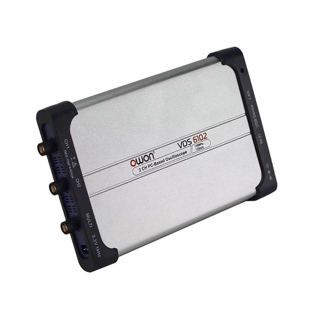
OWON OWON VDS6102A 2-kanaals USB-oscilloscoop (100 MHz)
The OWON VDS6000 Series PC Oscilloscope combines powerful performance with a sleek, ultra-thin design. With 100 MHz bandwidth, 1 GSa/s real-time sampling, and up to 14-bit resolution, it delivers highly accurate measurements. The built-in 5 MHz function generator, USB-C power supply, and optional WiFi connectivity make it incredibly versatile. Compatible with Windows, Linux, Android, and iOS, the VDS6000 is perfect for labs, fieldwork, and remote diagnostics – compact, flexible, and ready for any challenge. Features Bandwidth: 100 MHz Vertical resolution: 14 bits Rise time: ≤3.5 ns Memory: 10 Mpts Number of channels: 2 channels + 1 channel function generator Horizontal scale: 5ns - 100s/div Sample rate: Max. 1 GSa/s Maximum voltage: 40 V (peak - peak) Automatic measurements: Vpp, Vavg, Vamp, Vrms, Freq, Period, Vmax, Vmin, Vtop, Vbase, Overshoot, Preshoot, Rise Time, Connectivity: USB-C, LAN, Wifi (optional) Fall Time, Delay A→B↑, Delay A→B↓, +Width, -Width, +Duty, -Duty Bandwidth: 5 MHz Sample rate: 25 MSa/s Standard waveforms: Sine (0.1 Hz - 5 MHz), Square (0.1 Hz - 200 kHz), Ramp (1 Hz - 10 kHz), Pulse (1 Hz - 10 kHz) Resolution: 10 bits DC offset range (AC + DC): ±2.5 V Amplitude range: 10 mVpp - 5 Vpp Dimensions: 190 x 120 x 18 mm Weight: 380 g Downloads Manual Quick Guide PC Software MacOS Software
€ 330,00
-

OWON OWON XDG2035 2-ch Arbitrary Waveform Generator (35 Mhz)
The 2-channel OWON XDG2035 is a function/waveform generator that can generate signals with a maximum frequency of 35 Hz. The generator has a resolution of 1 µHz and a sample rate of 500 MSa/s.The OWON XDG2035 is capable of generating 6 standard waveforms and 150 arbitrary waveforms. With the included software you can write advanced functions up to 10 million points. Waveforms can be saved to the function generator's internal memory using a PC via USB or LAN.The OWON XDG2035 also supports SCPI commands and LabView. The function generator has an integrated high-quality frequency counter, which can operate from 100 to 200 MHz.Features Max. 35 MHz frequency output 500 MSa/s Sample rate, Vertical resolution 1μHz 14 bits Vertical Resolution, 10 Marb waveform length Comprehensive waveform output: 6 basic waveforms,and 150 built-in arbitrary waveforms Comprehensive modulation functions: AM, FM, PM, FSK, 3FSK, 4FSK, PSK, OSK, ASK, BPSK, PWM, Sweep, and Burst High-accuracy frequency counter integrated, supported range 100-200 MHz SCPI and LabVIEW supported 7 inch multi-touch screen (800 x 480 pixels) Specifications Channel 2 Frequency Output 35 MHz Sample Rate 500 MSa/s Vertical Resolution 14 bits Waveform Standard Waveform sine, square, pulse, ramp, noise, and harmonic Arbitrary Waveform exponential rise, exponential fall, sin(x)/x, step wave, and others, total 150 built-in waveforms, and user-defined arbitrary waveform Frequency (resolution 1 μHz) Sine 1 μHz-100 MHz Square 1 μHz ~ 30 MHz Pulse 1 μHz ~ 25 MHz Ramp 1 μHz ~ 3 MHz Noise (-3 dB, typical) 100 MHz Arbitrary Waveform 1 μHz ~ 15 MHz Harmonic 1 μHz ~ 50 MHz Accuracy ±2ppm, 25°C ±5°C Waveform Length 2 points - 10M points Amplitude Into 50Ω load 1mVpp ~ 10Vpp (≤25 MHz); 1mVpp ~ 5Vpp (≤60 MHz); 1mVpp ~ 2.5Vpp (≤100 MHz) Modulation Type AM, DSB-AM, FM, PM, ASK, FSK, PSK, BPSK, QPSK, 3FSK, 4FSK, OSK, PWM, SUM Frequency Counter Function Frequency, period, +width, -width, +duty, and -duty Frequency Range 100 ~ 200 MHz Frequency Resolution 7 digits Input/Output Input mode frequency counter, external modulation input, external trigger input, internal clock output, external reference clock input/output Communication Interface USB Host, USB Device, LAN, RS232 (optional) Mechanical specifications Dimensions 340 x 177 x 90 mm Weight 2.3 kg Included 1x OWON XDG2035 1x Power Cord 1x CD-ROM 1x Quick start guide 1x USB Cable 1x BNC-BNC Cable DownloadsQuick Guide
€ 339,00
-
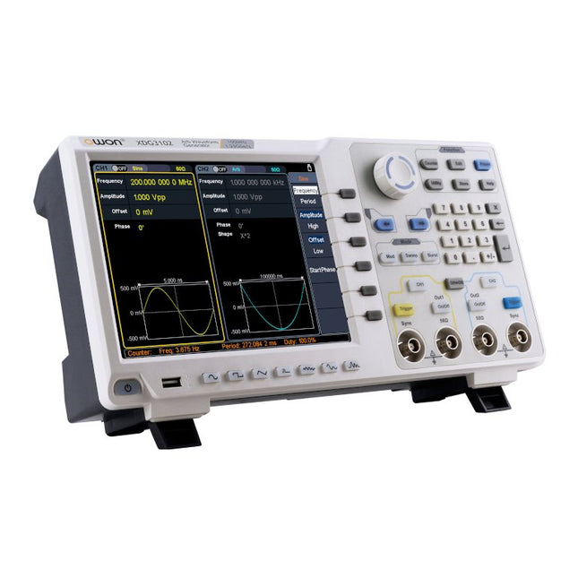
OWON OWON XDG3102 2-kanaals Arbitrary Waveform Generator (100 MHz)
Kenmerken Advanced DDS technology, up to 250MHz frequency output 1.25GS/s sampling rate, and 1 μHz frequency resolution Up to 1M arbitrary waveform length Vertical resolution: 14 bits Comprehensive waveform output: 6 groups waveforms, and 152 group built-in arbitrary waveforms Comprehensive modulation options: AM, FM, PM, FSK, 3FSK, 4FSK, PSK, OSK, ASK, BPSK, PWM, sweep, and burst High-accuracy frequency counter integrated, ranging from 100mHz till 200MHz SCPI and LabVIEW supported 8'' 800 x 600 pixels touch screen LCD Specificaties XDG3102 Channel 2 Frequency Output 100MHz Sample Rate 1.25GSa/s Vertical Resolution 14 bits Waveform Standard Waveform sine, square, pulse, ramp, noise, and harmonic Arbitrary Waveform exponential rise, exponential fall, sin(x)/x, step wave, and others, total of 150 built-in waveforms, and user-defined arbitrary waveform Frequency (resolution 1μHz) Sine 1μHz - 100MHz Square 1μHz - 40MHz Pulse 1μHz - 25MHz Ramp 1μHz - 5MHz Harmonic 1μHz - 50MHz Noise 120MHz (-3dB, typical) Arbitrary Waveform built-in waveform: 1uHz - 15MHzuser-defined waveform: 1uHz - 50MHz Accuracy ±1ppm, 0°C - 40°C Amplitude Amplitude (50Ω) 1mVpp - 10Vpp (≤40MHz); 1mVpp - 5Vpp (≤80MHz) 1mVpp - 2.5Vpp (≤120MHz); 1mVpp - 1Vpp (≤250MHz) Amplitude(high impedance) 2mVpp - 20Vpp (≤40MHz); 2mVpp - 10Vpp (≤80MHz); 2mVpp - 5Vpp (≤120MHz); 2mVpp - 2Vpp (≤250MHz) Resolution 1mV or 4 digits DC Offset Range (50Ω) ±(5 Vpk - Amplitude Vpp/2) Range (high-Z, open circuit) ±(10 Vpk - Amplitude Vpp/2) Accuracy ±(1% of |setting| + 1mV + Amplitude Vpp x 0.5%) Resolution 1mV or 4 digits Load Impedance 50Ω (typical) Accuracy ±(1% of setting + 1 mVpp) (typical, 1kHz sine, 0V offset) Sine Wave Spectrum Purity Harmonic Distortion Typical (0dB) DC - 1MHz: <-65dBc 1MHz - 10MHz: <-60dBc 10MHz - 120MHz: <-50dBc 120MHz - 200MHz: <-45dBc Total Harmonic Distortion ≤0.05 %, 10 Hz to 20 kHz, 1 Vpp Spurious (non-harmonic), Typical (0dB) ≤10MHz: <-70dBc >10MHz: <-70dBc + 6dB/ octave Phase Noise Typical (0 dBm, 10 kHz deviation) 10MHz: -110dBc/Hz Square Rise/Fall Time <5ns Overshoot <3% Duty Cycle 50.0% (fixed) Jitter (rms) 300ps + 100ppm Pulse Pulse Width 12ns - 996875s Leading/Trailing Edge Time ≤7ns Overshoot <3% Jitter (rms) 300ps + 100ppm Ramp Linearity ≤1% of peak output (typical, 1kHz, 1 Vpp, 50% symmetry) Symmetry 0% to 100% Harmonic Harmonic Order ≤16 Harmonic Type even, odd, all, user Harmonic Amplitude could be set for all the harmonics Harmonic Phase Arbitrary Waveform Length 2 points - 1M points Vertical Resolution 14 bits Minimum Rise/Fall Time <7ns Jitter (rms) 3ns Modulation Type AM, FM, PM, PWM, FSK, 3FSK, 4FSK, PSK, OSK, ASK, BPSK, sweep, and burst AM Carrier Waveform sine, square, ramp, and arbitrary (except DC) Source internal / external Modulating Waveform sine, square, ramp, noise, and arbitrary Depth 0.0% - 100.0% Modulating Frequency 2 mHz - 100 kHz FM Carrier Waveform sine, square, ramp, and arbitrary (except DC) Source internal / external Modulating Waveform sine, square, ramp, noise, and arbitrary Modulating Frequency 2 mHz - 100 kHz PM Carrier Waveform sine, square, ramp, and arbitrary (except DC) Source internal / external Modulating Waveform sine, square, ramp, noise, and arbitrary Phase Deviation 0° - 180° Modulating Frequency 2 mHz - 100 kHz PWM Carrier Waveform pulse Source internal / external Modulating Waveform sine, square, ramp, noise, and arbitrary Width Deviation 0 ~ minimum (pulse duty ratio, 100% - pulse duty ratio) Modulating Frequency 2 mHz - 100 kHz FSK / 3FSK / 4FSK Carrier Waveform sine, square, ramp, and arbitrary (except DC) Source internal / external Modulating Waveform square with 50% duty cycle Key Frequency 2 mHz - 1MHz PSK Carrier Waveform sine, square, ramp, and arbitrary (except DC) Source internal / external Modulating Waveform square with 50% duty cycle Key Frequency 2 mHz - 1MHz OSK Carrier Waveform sine, square, ramp, and arbitrary (except DC) Source internal Oscillation Time square with 50% duty cycle Key Frequency 2 mHz - 1MHz ASK Carrier Waveform sine, square, ramp, and arbitrary (except DC) Source internal / external Modulating Waveform square with 50% duty cycle Key Frequency 2 mHz - 1MHz BPSK Carrier Waveform sine, square, ramp, and arbitrary (except DC) Source internal Modulating Waveform square with 50% duty cycle Key Frequency 2 mHz - 1MHz Sweep Carrier Waveform sine, square, ramp, and arbitrary (except DC) Type linear, and log Direction up, and down Sweep Time 1 ms to 500s, ± 0.1% Trigger Source internal, external, and manual Burst Carrier Waveform sine, square, ramp, pulse, and arbitrary (except DC) Burst Count 1 to 50,000 period, infinite, gating Internal Period 10 ns - 500 s Gated Source external trigger Frequency Counter Function frequency period, +width, -width, +duty, and -duty Frequency Range 100mHz - 200MHz Frequency Resolution 7 digits Input / Output Display 8”800 x 600 pixels touch screen LCD Type frequency counter, external modulation input,external trigger input,external reference clock input / output Communication Interface USB Host, USB Device, and LAN Dimensions 340 x 177 x 90 mm Weight 2.50 kg
€ 650,00
-

OWON OWON XDM1041 True RMS Multimeter
De OWON XDM1041 is een snelle en uiterst nauwkeurige digitale True RMS tafelmultimeter met een 3,5-inch hoge resolutie LCD-scherm en 55000 counts. Zijn DC-spanningsnauwkeurigheid blijft binnen de 0,05% en hij kan tot 65 meetwaarden per seconde meten. Kenmerken 3,5" hoge resolutie LCD-scherm (480 x 320 pixels) 55000 counts DC-spanningsnauwkeurigheid binnen 0,05% Tot 65 metingen per seconde Ondersteunt dual line display Trendanalyse beschikbaar in de grafiekmodus AC True RMS-metingen (bandbreedte: 20 Hz – 1 kHz) SCPI-ondersteuning: bedien de multimeter op afstand via pc-software via USB-poort Data record functie, waarmee u de gemeten gegevens in het interne geheugen kunt opslaan en vervolgens de geregistreerde gegevens kunt lezen en verwerken met uw computer. Specificaties Meetbereik Resolutie Nauwkeurigheid DC-spanning 50,000 mV 0,001 mV 0,1% +10 500,00 mV 0,01 mV 0,05% +5 5,0000 V 0,0001 V 0,05% +5 50,000 V 0,001 V 0,05% +5 500,00 V 0,01 V 0,1% +5 1000,0 V 0,1 V 0,1% +10 AC-spanning 500 mV~750 V 20 Hz~45 Hz 1% +30 45 Hz~65 Hz 0,5% +30 65 Hz~1 KHz 0,7% +30 DC-stroom 500 uA 0,01 uA 0,15% +20 5000 uA 0,1 uA 0,15% +10 50 mA 0,001 mA 0,15% +20 500 mA 0,01 mA 0,15% +10 5 A 0,0001 A 0,5% +10 10 A 0,001 A 0,5% +10 AC-stroom 500 uA~500 mA 20 Hz~1 KHz 0,5% +20 5 A~10 A 1,5% +20 Weerstand 500 Ω 0,01 Ω 0,15% +10 5 KΩ 0,0001 KΩ 0,15% +5 50 KΩ 0,001 KΩ 0,15% +5 500 KΩ 0,01 KΩ 0,15% +5 5 MΩ 0,0001 MΩ 0,3% +5 50 MΩ 0,001 MΩ 1% +10 Frequentie 10.000 Hz~60 MHz / ±(0,2% +10) Capaciteit 50 nF~500 uF / 2,5% +10 5 mF~50 mF 5% +10 Diode 3,0000 V 0,0001 V / Continuïteit 1000 Ω 0,1 Ω Instelbare drempel Temperatuur K-type, PT100 Maximale weergave 55000 counts Datalogging functie Logging duur 15msZ9999,999s Logging lengte 1.000 meetpunten Display 3,5-inch TFT LCD (480x320 pixels) Power supply 230 V AC netspanning Afmetingen 200 x 88 x 150 mm Gewicht ca. 0,5 kg Inbegrepen 1x OWON XDM1041 Multimeter 1x Netsnoer 2x Meetsnoeren 1x Zekering 1x USB-kabel 1x Handleiding Downloads Programming handleiding PC Software
€ 94,38
-

OWON OWON XDM1241 True RMS Multimeter
The OWON XDM1241 is a fast, high-precision digital True RMS benchtop multimeter with a high-resolution 3.5-inch LCD and 50,000 counts. Its DC voltage accuracy is up to 0.05% and it can measure up to 65 values per second. Kenmerken 3.5" high-resolution LCD (480x320 pixels) 55000 counts, DC voltage accuracy up to 0.05% Up to 65 readings per second Dual line display supported Trend analysis accessible in chart mode AC True RMS measurements (bandwidth: 20 Hz – 1 kHz) SCPI support: Remote control the multimeter through PC software via USB port Data record function, you can record the measured data into internal memory, and then read and process the recorded data with your computer. Specificaties Measurement Range Resolution Accuracy DC Voltage 50.000 mV 0.001 mV 0.1% +10 500.00 mV 0.01 mV 0.05% +5 5.0000 V 0.0001 V 0.05% +5 50.000 V 0.001 V 0.05% +5 500.00 V 0.01 V 0.1% +5 1000.0 V 0.1 V 0.1% +10 AC Voltage 500 mV~750 V 20 Hz~45 Hz 1% +30 45 Hz~65 Hz 0.5% +30 65 Hz~1 KHz 0.7% +30 DC Current 500 uA 0.01 uA 0.15% +20 5000 uA 0.1 uA 0.15% +10 50 mA 0.001 mA 0.15% +20 500 mA 0.01 mA 0.15% +10 5 A 0.0001 A 0.5% +10 10 A 0.001 A 0.5% +10 AC Current 500 uA~500 mA 20 Hz~1 KHz 0.5% +20 5 A-10 A 1.5% +20 Resistance 500 Ω 0.01 Ω 0.15% +10 5 KΩ 0.0001 KΩ 0.15% +5 50 KΩ 0.001 KΩ 0.15% +5 500 KΩ 0.01 KΩ 0.15% +5 5 MΩ 0.0001 MΩ 0.3% +5 50 MΩ 0.001 MΩ 1% +10 Frequency 10.000 Hz~60 MHz / ±(0.2% +10) Capacitance 50 nF~500 uF / 2.5% +10 5 mF50 mF 5% +10 Diode 3.0000 V 0.0001 V / Continuity 1000 Ω 0.1 Ω Adjustable threshold Temperature K type, PT100 Max Display 55,000 counts Data-logging Function Logging Duration 15ms~9999.999s Logging Length 1,000 points Display 3.5" TFT LCD (480x320 pixels) Power supply Lithium battery via USB-C or 5 V DC input Dimensions 235 x 88 x 65 mm Weight approx. 0.5 kg Inbegrepen 1x OWON XDM1241 Multimeter 2x Test leads 1x USB cable 1x USB to DC cord 1x Manual Downloads Programming Manual PC Software
€ 108,90
-

OWON OWON XDM2041 True RMS Multimeter
The OWON XDM2041 is a low-cost, high-precision benchtop multimeter. The meter has a True RMS function to measure the AC voltage and current and it has a reading speed of up to 65 values per second. Also, the XDM2041 is equipped with functions such as measuring 2-wire and 4-wire resistance. The XDM2041 is able to store data internally in the memory of the meter and display it on the 3.7" high-resolution LCD display. Up to 1000 points can be stored and the time interval can be varied from 15ms to 9999s. By means of the RS232 port on the back of the device, the meter can be programmed and controlled via SCPI. Specificaties Measurement Range Resolution Accuracy ±(% of reading + LSB) DC Voltage 50.000mV 0.001mV 0.1%+10 500.00mV 0.01mV 0.025%+5 5.0000V 0.0001V 0.025%+5 50.000V 0.001V 0.03%+5 500.00V 0.01V 0.1%+5 1000.0V 0.1V 0.1%+5 AC Voltage 500mv-750v 20Hz~45Hz 1%+30 45Hz~65Hz 0.5%+30 65Hz~1KHz 0.7%+30 DC Current 500uA 0.01uA 0.15%+20 5000uA 0.1uA 0.15%+10 50mA 0.001mA 0.15%+20 500mA 0.01mA 0.15%+10 5A 0.0001A 0.5%+10 10A 0.001A 0.5%+10 AC Current 500uA-500mA 20 Hz-1 kHz 0.5%+20 5A-10A 1.5%+20 Resistance 500Ω 0.01Ω 0.1%+10 5KΩ 0.0001KΩ 0.1%+5 50KΩ 0.001KΩ 0.1%+5 500KΩ 0.01KΩ 0.1%+5 5MΩ 0.0001MΩ 0.25%+5 50MΩ 0.001MΩ 0.1%+10 Four-wire resistance 500Ω 0.01Ω 0.1%+10 5KΩ 0.0001KΩ 0.1%+5 50KΩ 0.001KΩ 0.1%+5 Measurement Range Resolution Accuracy ±(% of reading + % of range) Frequency 10.000Hz-60MHz / ±(0.2%+8) Capacitance 50nF-500uF / 2.5%+5 5mF-50mF 5%+8 Diode 3.0000 V 0.0001V / Continuity 1000 Ω 0.1Ω / Temperature K type,PT100 Display 55,000 Data-logging Function Logging Duration 15ms-9999s Logging Length 1,000 points Inbegrepen 1x OWON XDM2041 Multimeter 2x Multimeter leads 2x Alligator clips 1x Fuse 1x Manual Downloads User manual Programming manual PC software
€ 154,88
-
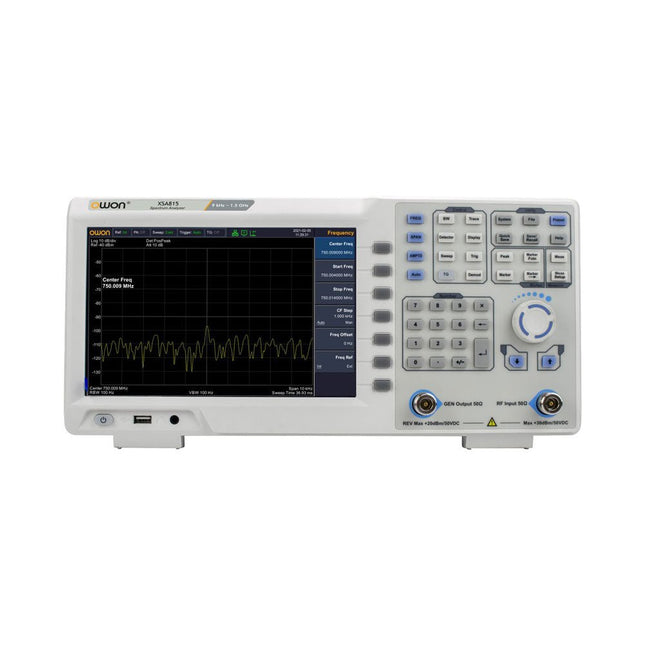
OWON OWON XSA815-TG Spectrum Analyzer (9 kHz – 1.5 GHz)
The OWON XSA815-TG 9 kHz-1.5 GHz is a cost effective spectrum analyzer with tracking generator included and a frequency resolutions of 1 Hz.Features Frequency Range from 9 kHz to 1.500009 GHz 9-inch display 9 kHz to 1 MHz -95 dBm Displayed Average Noise Level, 1 MHz to 500 MHz 140 dBm (Typical), <-130 dBm Phase Noise -10 kHz < -80 dBc/Hz 100 kHz < -100 dBc/Hz 1 MHz < -115 dBc/Hz Resolution Bandwidth (-3 dB): 1 Hz to 1 MHz, in 1-3-5-10 sequence Tracking Generator Kit: 100 kHz to 1.500009 GHz Specifications Frequency Range 9 kHz to 500.009 MHz Frequency Resolution 1 Hz Frequency Span 9 kHz to 1.500009 GHz Span Range 0 Hz, 100 Hz to max frequency of instrument Span Uncertainty ± span / (sweep points-1) SSB Phase Noise (20°C to 30°C, fc=1 GHz) Carrier Offset 10 kHz < -80 dBc/Hz | 100 kHz < -100 dBc/Hz | 1 MHz < -115 dBc/Hz Resolution Bandwidth (-3 dB) 1 Hz to 1 MHz, in 1-3-5-10 sequence RBW Accuracy < 5% typical Resolution Filter Shape Factor (60 dB: 3 dB) <5 typical Video Bandwidth (-3 dB) 10 Hz to 1 MHz, in 1-3-5-10 sequence Amplitude measurement range DANL to +10 dBm, 100 kHz to 10 MHz, Preamp Off DANL to +20 dBm, 10 MHz to 1.5 GHz, Preamp Off Reference Level -80 dBm to +30 dBm, 0.01dB by step Preamp 20 dB, nominal, 100 kHz to 1.5 GHz Input Attenuator 0 to 40 dB, 1 dB by step Display Average Noise Level Input attenuation = 0 dB, RBW = VBW = 100 Hz, sample detector, trace average ≥ 50, 20°C to 30°C, input impedance = 50 Ω) Preamp Off 9 kHz to 1 MHz -95 dBm (Typical), <-88 dBm Preamp Off 1 MHz to 500 MHz -140 dBm (Typical), <-130 dBm Preamp On 100 kHz to 1 MHz -135 dBm (Typical), <-128 dBm Preamp On 1 MHz to 500 MHz -160 dBm (Typical),<-150 dBm Tracking Generator (optional) Frequency Range 100 kHz to 1.500009 GHz Output power level range -40 dBm to 0 dBm Output level resolution 1 dB Output flatness Relative to 50 MHz | ±3 dB Tracking generator spurious Harmonic spurious -30 dBc (Tracking generator output power -10 dBm) Non-harmonic spurious -40 dBc (Tracking generator output power -10 dBm) Tracking generator to input terminal isolation -60 dB (Tracking generator output power 0 dBm) Tracking generator to input terminal isolation -60 dB (Tracking generator output power 0 dBm) Tracking generator to input terminal isolation -60 dB (Tracking generator output power 0 dBm) Dimensions 375 x 185 x 120 mm Weight 3.7 kg Included 1x XSA815-TG 1x 220 V AC power cord 1x USB Cable 1x Quickstart guide Downloads Quick Guide Specifications
€ 907,50
-

Elektor Digital PC Programming (E-book)
A Small Basic Approach There are many different PC programming languages available on the market. Some have beautiful names; some have easy to use development tools. Others have incredible power. They all have one thing in common: they assume that you have, or want to have, a knack for technology and difficult to read commands. In this book we take a practical approach to programming. We assume that you simply want to write a PC program, and write it quickly. Not in a professional environment, not in order to start a new career, but for plain and simple fun... or just to get a task done. Therefore we use Small Basic. You will have an application up and running in a matter of minutes. You will understand exactly how it works and be able to write text programs, graphical user interfaces, and advanced drivers. It is so simple; you don't even need to be an adult!
€ 29,95
Leden: € 26,96
-
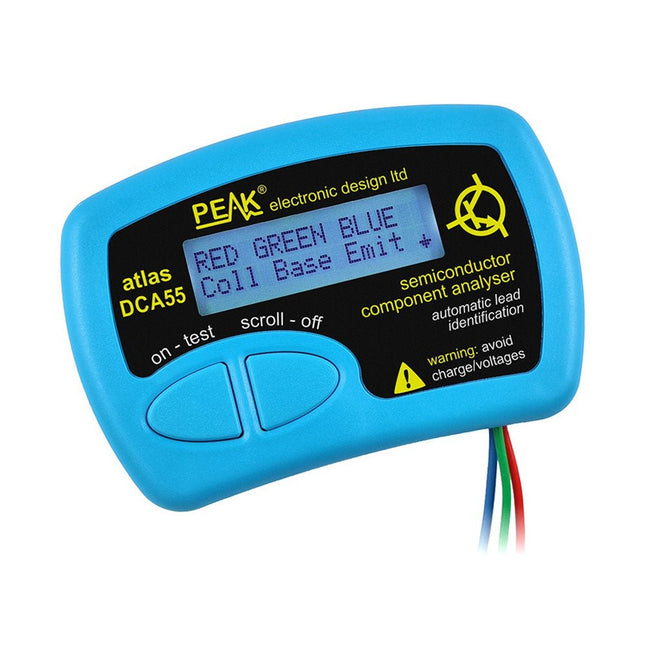
Peak Peak Atlas DCA55 Semiconductor Analyzer
The Peak Atlas DCA55 is great for automatically identifying the type of semiconductor on the test leads as well as the pinout and many other parameters. Supports transistors MOSFETs, JFETs (gate pin only can be identified), diodes, LEDs and lots more. Automatically identifies type of component, pinout and other important parameters. Now features transistor leakage measurement and Germanium/Silicon identification. Component Support Bipolar transistors (NPN/PNP inc Silicon/Germanium) Darlington transistors (NPN/PNP) Enhancement mode MOSFETs (N-Ch and P-Ch) Depletion mode MOSFETs (N-Ch and P-Ch) Junction FETs (N-Ch and P-Ch). Only gate lead identified. Diodes and diode networks (2 and 3 lead types). LEDs and bi-colour LEDs (2 lead and 3 lead types). Low power sensitive Triacs and Thyristors (<5 mA trigger and hold) Measurements Part type identification Pinout identification BJT current gain (hFE) BJT base emitter voltage (Vbe) BJT collector leakage current MOSFET gate threshold voltage Diode forward voltage drop (Vf) Specificaties Analyzer type Transistors, Diodes, LEDs, MOSFETs, JFETs Pinout detection Full pinout (only Gate on JFETs) Pinout configuration Connect any way round Transistor measurements Vbe, hFE, Iceo MOSFET measurements Vgs(on) Diode measurements Vf Probe type Universal grabber type Battery Single AAA cell (supplied). Life typically 1300 ops Test conditions Typically 5 mA, 5 V peak Display type Alphanumeric LCD (with backlight) Inbegrepen DCA55 Semiconductor Component Analyser instrument Comprehensive illustrated user guide Fitted universal hook probes AAA Alkaline battery Downloads Datasheet (EN) User Guide (EN)
€ 83,49
-
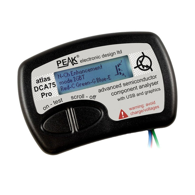
Peak Peak Atlas DCA75 Pro (Advanced Semiconductor Analyzer)
The DCA75 Pro is a great instrument that combines ease-of-use with amazing features. It can automatically identify a huge range of semiconductors, automatically identify pinouts and measure detailed parameters. Kenmerken Built-in graphics display (now backlit) to show detailed schematic of the component you're testing as well as pinout and measurement data. USB connectivity to allow curve tracing, data storage/retrieval and device matching on your Windows PC (Windows 7 and higher). Single internal AAA alkaline cell for standalone operation. Component Support Bipolar transistors (NPN/PNP inc Silicon/Germanium) Darlington transistors (NPN/PNP) Enhancement mode MOSFETs (N-Ch and P-Ch) Depletion mode MOSFETs (N-Ch and P-Ch) Junction FETs (N-Ch and P-Ch). Both symmetrical and asymmetrical types Enhancement IGBTs (N-Ch and P-Ch) Diodes and diode networks (2 and 3 lead types) Zener diodes (up to about 9 V) Voltage regulators (up to about 8 V) LEDs and bi-colour LEDs (2 lead and 3 lead types) Low power sensitive Triacs and Thyristors (<10 mA trigger and hold) Measurements BJT current gain (hFE) BJT base emitter voltage (Vbe) BJT collector leakage current MOSFET on and off gate threshold voltages MOSFET transconductance JFET pinch-off voltage JFET transconductance JFET IDSS (drain current for Vgs=0) IGBT on and off gate threshold voltages IGBT transconductance Voltage regulator output voltage Voltage regulator quiescent current consumption Voltage regulator drop-out voltage Zener voltage Diode forward voltage drop Specificaties Analyzer type Semiconductor components Component detection Automatic Pinout detection Automatic, connect any way round Display type Graphic LCD (now backlit) Interface type USB for optional PC connection PC functions Curve tracing (Windows 7 and higher) Software Included on USB drive for Windows 7 and higher Battery Single AAA cell (supplied) Inbegrepen Peak Atlas DCA75 Pro PC software on a USB Flash Drive for Windows 11, 10, 8, 7, XP Micro USB cable Fitted universal premium hook probes AAA Alkaline battery Downloads Datasheet (EN) User Guide (EN) Software Installation Guide (EN) Software and Firmware Package
€ 192,39


