This is a RGB LED matrix digital clock designed for Raspberry Pi Pico. It incorporates high precision RTC chip DS3231, photosensor, buzzer, IR receiver, and buttons, features multiple functions including accurate electronic clock, temperature display, auto brightness adjustment, alarm, and button config. The important part is, rich open source codes and development tutorials are also provided to help you fast get started with Raspberry Pi Pico and make your own original electronic clock. Features Standard Raspberry Pi Pico header, supports Raspberry Pi Pico series Using P3 fine-pitch RGB LED matrix panel, with 2048 individual RGB LEDs, 64×32 pixels, 3 mm pitch, allows displaying text, colorful image, or animation Onboard high precision RTC chip DS3231, with backup battery holder (battery included), maintains accurate timekeeping when main power is off Real-Time Clock Counts Seconds, Minutes, Hours, Date of the Month, Month, Day of the Week, and Year with Leap-Year Compensation Valid Up to 2100 Optional format: 24-hour OR 12-hour with an AM/PM indicator 2x programable alarm clock Digital temperature sensor output: ±3°C accuracy Embedded photosensor for auto brightness adjustment due to the ambient light, power saving and eye care Embedded buzzer for alarm or hourly ring, etc. IR receiver, combined with the IR remote controller, supports IR wireless control 5x buttons for configuration, reset, and code programming Quality acrylic back panel and dimmer panel, better looking, more comfortable displaying Comes with development resources and manual (Raspberry Pi Pico C/C++ and MicroPython examples) Included 1x Pico-RGB-Matrix-P3-64x32 base board 1x RGB-Matrix-P3-64x32 LED matrix and accessories 1x Black acrylic back panel 1x Dark brown acrylic front panel 1x IR remote controller 1x Double-sided tape 1x Screws pack Downloads Documentation
Het Data Logging Carrier Board bevat aansluitingen voor I2C via een Qwiic connector of standaard 0.1' doorgemetalliseerde pinnen, samen met SPI en seriële UART aansluitingen voor het loggen van data van randapparatuur die gebruik maakt van deze communicatie protocollen. Met het Data Logging Carrier Board kunt u de voeding schakelen van zowel de Qwiic-connector op het bord als een speciale 3,3V voedingsrail voor niet-Qwiic-randapparatuur, zodat u kunt kiezen wanneer u de randapparatuur waarvan u de gegevens verzamelt, van stroom voorziet. Het bevat ook een oplaadcircuit voor lithium-ion batterijen met één cel en een apart batterijcircuit om een real-time klok op uw processorbord van stroom te voorzien. Eigenschappen M.2 MicroMod Connector microSD socket USB-C Connector 3.3 V 1 A spanningsreglaar Qwiic Connector Boot/Reset toetsen RTC backup-batterij & laadcircuit Onafhankelijke 3.3V spanningsregelaars voor Qwiic bus andere periferie Digitale uitgang van het processorbord schakelt de sluimerstand M2.5 x 3 mm met kruiskopschroef meegeleverd
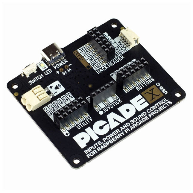
Turn your Raspberry Pi into a retro games console! Picade X HAT includes joystick and button inputs, a 3 W I²S DAC/amplifier, and soft power switch. This HAT has all the same great features as the original Picade HAT but now has no-fuss female Dupont connectors to hook up your joystick and buttons. Simply pop Picade X HAT onto your Pi, plug a USB-C power supply into the connector on the HAT (it back-powers your Pi through the GPIO, so no need for a separate power supply), wire up your controls, and install the driver! It's ideal for your own DIY arcade cabinet builds, or for interfaces that need big, colourful buttons and sound. Features I²S audio DAC with 3 W amplifier (mono) and push-fit terminals Safe power on/off system with tactile power button and LED USB-C connector for power (back-powers your Pi) 4-way digital joystick inputs 6x player button inputs 4x utility button inputs 1x soft power switch input 1x power LED output Plasma button connector Breakout pins for power, I²C, and 2 additional buttons Picade X HAT pinout Compatible with all 40-pin Raspberry Pi models The I²S DAC blends both channels of digital audio from the Raspberry Pi into a single mono output. This is then passed through a 3 W amplifier to power a connected speaker. The board also features a soft power switch that allows you turn your Pi on and off safely without risk of SD card corruption. Tap the connected button to start up, and press and hold it for 3 seconds to fully shutdown and disconnect power. Software/Installation Open a terminal and type curl https://get.pimoroni.com/picadehat | bash to run the installer. You'll need to reboot once the installation is complete, if it doesn't prompt you to do so. The software does not support Raspbian Wheezy Notes With USB-C power connected through Picade X HAT you'll need either to tap the connected power button or the button marked 'switch' on the HAT to power on your Pi.
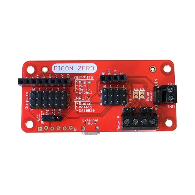
The Picon Zero is an add-on for the Raspberry Pi. It has the same size as a Raspberry Pi Zero, making it ideal to function as a pHat. Of course, it can be used on any other Raspberry Pi via a 40-pin GPIO connector.As well as two full H-Bridge motor drivers, the Picon Zero has several Input/Output pins giving you multiple configuration options. That allows you to easily add outputs or analog inputs to your Raspberry Pi without any complicated software or kernel-specific drivers. At the same time, it opens up 5 GPIO pins from the Raspberry Pi, and it provides the interface for an HC-SR04 ultrasonic distance sensor.The Picon Zero comes with all components, including the headers and screw terminals, fully soldered. Soldering isn't required. You can use it right out of the box.Features
pHat format PCB: 65 mm x 30 mm
Two full H-Bridge motor drivers. Drive up to 1.5 A continuously per channel, at 3 V - 11 V.
Each motor output has both a 2-pin male header and a 2-pin screw terminal.
The motors can be powered from the Picon Zero's 5 V or an external power source (3 V - 11 V).
The Picon Zero's 5 V can be selected to be from the Raspberry Pi's 5 V line, or a USB connector on the Picon Zero. That means that you can effectively have 2 USB battery banks: one to power the servos and motors on the Picon Zero and the other to power the Pi.
4 Inputs that can accept up to 5 V. These inputs can be configured as follows:
Digital inputs
Analog inputs
DS18B20
DHT11
6 Outputs that can drive 5 V and be configured as:
Digital Output
PWM Output
Servo
NeoPixel WS2812
All Inputs and Outputs use GVS 3-pin male headers.
4-pin female header that connects directly to an HC-SR04 ultrasonic distance sensor.
8-pin female header for Ground, 3.3 V, 5 V, and 5 GPIO signals allowing you to add their additional features.
Hardware ConfigurationPicon Zero has two jumpers for setting the hardware configuration. Ensure that you have placed them in the correct position.
JP1 – Board 5 V Selector. This jumper selects where to get the 5 V power from for the Picon Zero Outputs. The options are:
Jumper at the top between RPI and 5 V. The 5 V power for the board is taken from the Raspberry Pi pins on the GPIO connector. Because of the low power output devices and the 5 V motors, all devices can be powered with a single 5 V power input.
Jumper at the bottom between USB and 5 V. The 5 V power is taken from the microUSB connector on the Picon Zero. Useful for higher power output devices, since you can provide extra power through the micro-USB connector on the board
JP2 – Motor Power Selector. This jumper selects where the motors get the power. The two options here are the following:
Jumper at the top between MotorPower and Vin. The motors are driven via the 2-pin screw terminal. The voltage can be between 3 V and 11 V. Useful for motors that require a voltage different from 5 V, or that require more current than is available on either of the USB input connectors
Jumper at the bottom between 5 V and MotorPower. The motors are driven from the board's 5 V.
Raspberry Pi ConfigurationThe Picon Zero is an I²C device. Make sure your Raspberry Pi is set up correctly to use I²C and SMBus:
sudo apt-get install python-smbus python3-smbus python-dev python3-dev
sudo nano /boot/config.txt Add the following lines at the end of the file
dtparam=i2c1=on
dtparam=i2c_arm=on
Press Ctrl-X and use the default prompts to save
sudo reboot
Plugin the Picon Zero onto the Pi and run i2cdetect -y 1If everything goes well, you will see the Picon Zero showing up as address 22 as shown below:
Features Compatible with Raspberry Pi 4 only
Cutout in lid for 40x30mm heatsink or Fan SHIM
Super-slimline profile Fully HAT-compatible Protects your beloved Pi Clear top and base leave Raspberry Pi 4 visible GPIO cut-out Handy laser-etched port labels Leaves all ports accessible Made from lightweight, high-quality, cast acrylic Great for hacking and tinkering! Made in Sheffield, UK Weighing just over 50 grams, the case is lightweight and ideal for mounting to any surface. No tools are required for assembly or disassembly. The dimensions are: 99 × 66 × 15 mm. In the video below you can see a quick assembly guide.
Add colors to your projects with this collection of red, green, yellow, blue and white LEDs. They come with various current limiting resistors in order to protect the parts and control the brightness.Included
10 mm LEDs
1x red
1x green
1x yellow
1x blue
1x white
5 mm LEDs
5x red
5x green
5x yellow
5x blue
5x white
3 mm LEDs
5x red
5x green
5x yellow
5x blue
5x white
25x 330 Ω resistors
10x 1 kΩ resistors
10x 10 kΩ resistors
10x 100 kΩ resistors
10x 1 MΩ resistors
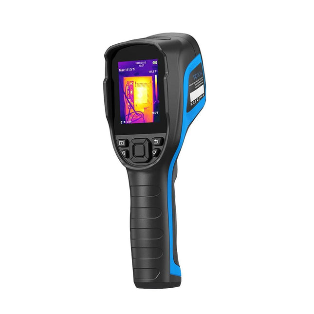
De TOPDON TC004 warmtebeeldcamera biedt een breed temperatuurbereik van -20°C tot 350°C met een batterijlevensduur van 12 uur. De camera heeft een infraroodcamera met een hoge resolutie van 256 x 192 pixels, wat zorgt voor heldere, gedetailleerde beelden.
Met een thermische gevoeligheid van 0,05°C kan hij subtiele temperatuurveranderingen detecteren. De camera detecteert automatisch het midden, warme en koude plekken, waardoor de visuele temperatuuranalyse wordt verbeterd. Het brede gezichtsveld van 56° legt meer vast in één enkele opname zonder dat er focusaanpassingen nodig zijn.
De TC004 biedt nauwkeurige metingen met een nauwkeurigheid van ±2°C, een NETD van minder dan 40 mK en een resolutie tot 0,1°C. Hij ondersteunt zowel standalone als PC modi, zodat gebruikers beelden kunnen uploaden en projecteren voor eenvoudige analyse. De ingebouwde LED-lamp maakt gebruik bij weinig licht mogelijk en de professionele software vereenvoudigt het delen van gegevens.
Kenmerken
Breed temperatuurbereik van −20°C tot 350°C
Realtime foto- en video-opname
5 kleurenpaletten voor meer mogelijkheden
Statief monteerbaar voor een stabiel zicht
Alarm voor hoge en lage temperatuur
Bewaak temperatuurveranderingen met golfvormgrafieken
Langdurige batterijduur van 12 uur
PC-beeldanalyse en directe projectie
Ingebouwd LED-licht
Specificaties
TC004
TC004 SE
TC004 Lite
Display
2,8" kleuren-TFT (320 x 240 pixels)
2,8" kleuren-TFT (320 x 240 pixels)
2,8" kleuren-TFT (320 x 240 pixels)
IR-lichtresolutie
256 x 192 pixels
256 x 192 pixels
160 x 120 pixels
Spectraal bereik
8~14 μm
8~14 μm
8~14 μm
FOV
52,5° x 39,5°
56° x 42°
40° x 30°
Opslag
2 GB RAM + 16 GB TF-kaart
32 GB (ingebouwd)
512 MB (ingebouwd)
Meetbereik
−20~350°C
−20~550°C
−20~550°C
Temperatuurresolutie
0,1°C
0,1°C
0,1°C
Meetmodi
Centrum/heetste punt/koudste punt
Centrum/heetste punt/koudste punt
Centrum/heetste punt/koudste punt
Meetnauwkeurigheid
±2°C of ±2%
±2°C of ±2%
±2°C of ±2%
Framerate
25 Hz
25 Hz
25 Hz
Brandpuntsafstand
3,2 mm (0,12")
3,2 mm (0,12")
2,6 mm (0,1")
NETD
<40 mK
<40 mK
<40 mK
Vergroting
1x/2x/4x (digitale zoom)
1x/2x/4x (digitale zoom)
1x/2x/4x (digitale zoom)
Statiefschroefgat
Ja
Ja
Ja
Alarm hoge/lage temperatuur
Ja
Ja
Ja
LED-licht
Ja
Ja
Nee
Video-opname
Ja
Ja
Nee
Automatische uitschakeling
5 min, 10 min, 20 min, UIT
5 min, 10 min, 20 min, UIT
5 min, 10 min, 20 min, UIT
Batterij
Ingebouwde batterij van 5000 mAh
Ingebouwde batterij van 5300 mAh
Ingebouwde batterij van 2900 mAh
Oplaadtijd
4 uur
4 uur
4 uur
Stand-bytijd
12 uur
16 uur (hoge helderheid)21 uur (lage helderheid)
15 uur
Besturingssysteem
Standalone gebruik/Windows-apparaten
Standalone gebruik/Windows-apparaten
Standalone gebruik
PC-gebaseerde analyse
Ondersteunt beeldanalyse met PC
Ja
Nee
Afmetingen
240 x 70 x 90 mm
240 x 70 x 90 mm
240 x 70 x 90 mm
Gewicht
520 g
520 g
520 g
Inbegrepen
1x TOPDON TC004 Warmtebeeldcamera
1x USB-voeding
4x Stekkers (EU, UK, US en AU)
1x USB-kabel
1x Opbergtas
1x Manual
Downloads
Datasheet
Manual
Entièrement mise à jour pour le Raspberry Pi 5
Raspberry Pi 5 est un petit ordinateur intelligent, de construction britannique qui regorge de potentiel. Fabriqué à l'aide d'un processeur économe en énergie, le Raspberry Pi est conçu pour vous aider à apprendre le codage, découvrir comment fonctionne un ordinateur et construire vos propres projets uniques et incroyables. Ce guide est conçu pour vous montrer à quel point il est facile de démarrer.
Apprendre à :
Configurez votre Raspberry Pi, installez son système d'exploitation, et commencez à utiliser cet ordinateur entièrement fonctionnel.
Commencez à coder des projets, avec des guides étape par étape utilisant les langages de programmation Scratch 3, Python et MicroPython.
Expérimentez en connectant des composants électroniques, et amusez-vous à créer des projets incroyables.
Nouveauté de la 5ème édition :
Mise à jour pour les derniers ordinateurs Raspberry Pi : Raspberry Pi 5 et Raspberry Pi Zèro 2 W.
Couvre le dernier système d'exploitation Raspberry Pi.
Comprend un nouveau chapitre sur le Raspberry Pi Pico !
Téléchargements
GitHub
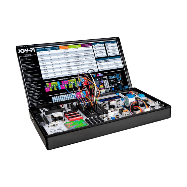
De Joy-Pi Advanced is een compact en krachtig instrument waarmee je snel en eenvoudig je projecten kunt realiseren. Of je nu veel of weinig ervaring hebt, met de Joy-Pi Advanced kun je je creativiteit de vrije loop laten. Dankzij de compatibiliteit met een groot aantal platformen, waaronder Raspberry Pi, Raspberry Pi Pico, Arduino Nano, BBC micro:bit en NodeMCU ESP32, kun je eenvoudig en snel toegang krijgen tot het platform van je voorkeur.
Daarnaast heeft de Joy-Pi Advanced meer dan 30 stations, lessen en modules, waardoor je een onbeperkt aantal manieren hebt om je projecten uit te voeren. Met het zelfontwikkelde leercentrum kun je niet alleen je vaardigheden verbeteren, maar ook nieuwe projecten maken. Het leercentrum biedt een schat aan informatie en tutorials die je stap voor stap door je projecten begeleiden.
Joy-Pi Advanced wordt in het bijzonder gekenmerkt door zijn intelligente schakeleenheden, die een uitgebreid gebruik van de beschikbare pinnen mogelijk maken. In totaal zijn er drie schakeleenheden geïntegreerd, elk voorzien van 12 individuele schakelaars die zorgen voor een nauwkeurige aansturing van de aangesloten sensoren en modules. Dit systeem lost het bekende probleem van het beperkte aantal pinnen op dat optreedt bij conventionele microcontrollers. Met de schakeleenheden kun je een groot aantal sensoren en modules parallel aansturen door ze afzonderlijk aan en uit te schakelen. Dit simuleert meervoudige pintoewijzing, waardoor je het volledige vermogen van je projecten kunt benutten zonder afbreuk te doen aan de functionaliteit.
Door onze innovatieve adapter boards en het micro:bit slot te combineren, bereiken we naadloze compatibiliteit met een breed scala aan microcontrollers zoals Raspberry Pi Pico, NodeMCU ESP32, micro:mit en Arduino Nano. De speciaal ontwikkelde adapterkaarten zijn zo ontworpen dat ze perfect passen bij de betreffende microcontroller. Door de microcontroller op het juiste adapterboard aan te sluiten en deze vervolgens in het micro:bit slot te steken, wordt de Joy-Pi Advanced snel en eenvoudig compatibel met de verschillende microcontrollers. Dit zorgt voor een naadloze integratie van het platform van je voorkeur en de mogelijkheid om de sterke punten van de verschillende microcontrollers te combineren in je projecten. Op deze manier kun je je volledig richten op je creatieve projecten zonder dat je je zorgen hoeft te maken over de compatibiliteit van verschillende microcontrollers. De Joy-Pi Advanced vereenvoudigt het ontwikkelproces en geeft je de mogelijkheid om je projecten flexibel en individueel te ontwerpen.
Kenmerken
Sterk geïntegreerd ontwikkelplatform & leercentrum
Snel, eenvoudig & draadloos combineren van verschillende sensoren & actuatoren
Installatieoptie voor Raspberry Pi 4
Compatibel met verschillende microcontrollers
Zelfontwikkeld, didactisch leerplatform voor Raspberry Pi & Windows
Specificaties
Compatibel met
Raspberry Pi 4, Arduino Nano, NodeMCU ESP32, BBC micro:bit, Raspberry Pi Pico
Geïnstalleerde sensoren, actuatoren & componenten
39
Leerplatform
Meer dan 40 items in de kennisdatabase, 10 projecten, 10 lessen, 14 visies
Displays
7-segment display, 16x2 display, 1,8' TFT-display, 0,96" OLED-display, 8x8 RGB-matrix
Sensoren
DS18B20, schoksensor, hallsensor, barometer, geluidssensor, gyroscoop, PIR-sensor, Lichtbarrière, NTC, Lichtsensor, 6x aanraaksensor, kleurensensor, ultrasone afstandssensor, DHT11 temperatuur- & vochtigheidssensor
Controle
Joystick, 5x schakelaars, potentiometer, draaiencoder, 4x4 knoppenmatrix, relais, PWM-ventilator
Motoren
Servo-interface, Stappenmotorinterface, Trilmotor
Meet- en conversiemodules
Analoog-digitaalomzetter, niveauomzetter, voltmeter, variabele spanningsbron
Andere onderdelen
RTC real-time klok, zoemer, EEPROM-geheugen, infrarood ontvanger, breadboard, RFID-lezer
Adapterkaarten
Adapter voor NodeMCU ESP32, Arduino Nano & Raspberry Pi Pico, Board connectors voor Raspberry Pi & externe boards
Elektronische onderdelen
Infrarood afstandsbediening, RFID-chip, RFID-kaart, 6x krokodillenklemmen, microSD-kaartlezer, servomotor, stappenmotor, 32 GB microSD-kaart
Onderdelen
40x weerstanden, 3x groene LED's, 3x gele LED's, 3x rode LED's, 1x transistor, 5x knoppen, 1x potentiometer, 2x condensatoren
Andere accessoires
Schroevenassortiment, schroevendraaier, accessoire-opbergtas, voeding & voedingskabel, servo bevestiging
Stroomvoorziening
Ingebouwde voeding: 36 W, 12 V, 3 A Behuizingsconnector: Kleine apparaat stekker C8
Spanningsuitgangen
12 V, 5 V, 3,3 V, variabele spanningsuitgang (2-11 V)
Databussen & signaaluitgangen
I²C, SPI, Analoog naar digitaal converter
Batterij (RTC)
CR2032
Afmetingen
327 x 200 x 52 mm
Vereist
Raspberry Pi 4 met minstens 2 GB RAM
Downloads
Joy-Pi website
Datasheet
Manual
De MDP-P906 heeft een ingebouwde ventilator en een maximaal uitgangsvermogen van 300 W, wat toereikend is voor een breed scala aan testbehoeften en toepassingen. Via 2,4 GHz draadloze communicatie kan hij worden aangesloten op de MDP-M01 Smart Digital Monitor module om daarmee een flexibele combinatie van meerdere kanalen van 300 W per kanaal te kunnen realiseren. De MDP-P906 heeft een basis, stabiliteit en betrouwbaarheid die te vergelijken is met een professionele voeding. Hij kan puur stroom leveren én krachtige functies hieraan toevoegen, zoals programmeerbare uitgang, getimede uitgang, getimede regeling, automatische compensatie, boost modus, enz. Dit maakt hem tot een kosteneffectieve, slimme en op maat programmeerbare lineaire DC-voeding. De MDP-P906 heeft een zorgvuldig CNC-gefreesde aluminium behuizing, met verfijnde afwerking, eigentijds, bescheiden en prachtig uiterlijk. Hij wijkt hiermee volledig af van het standaard uiterlijk van een traditionele desktop voeding. Door een stackable modulair ontwerp en de draadloze communicatie kan de MDP-P906 onafhankelijk of onderling gekoppeld worden gebruikt, zowel in de normale werkruimte als bij onderhoud op locatie. De MDP-P906 is een perfecte oplossing voor elektrotechnici, met name servicemonteurs, om bij verschillende situaties en toepassingen de stroom te leveren. Ingebouwde stille ventilator, instant cooling, voor een stabiele en efficiënte output! Slimme lineaire compensatie, constante spanning & constante stroom Positieve en negatieve output, series boost, parallelle stroomverdeling Toepassingen Universele tests en onderwijsexperimenten in R&D laboratoria Onderhoud van digitale producten Eigendomsverificatie en foutdiagnose van apparaten en circuits Noodstroomvoorziening voor modelvliegtuigen en voertuigen Voedingen testen van RF en microgolfcircuits of -modules Kwaliteitscontrole en kwaliteitsinspectie Zuivere voeding voor zeer nauwkeurige digitaal-analoge hybride circuits en Hi-Fi audioapparaten Specificaties Input DC 4.2-30 V / 14 A (Max)QC 3.0/PD2.0, 20 V / 5 A (Max) Uitgang 0-30 V / 0-10 A, 300 W (Max) Conversie efficiëntie 95% Output resolutie 10 mV / 2 mA, tot 1 mV / 1 mA via Display Control module Output nauwkeurigheid 0,03%+5 mV0,05%+2 mV Adjustment rate Load adjustment rate <±0,01%Power adjustment rate <±0,01% Ripple en noise <250 uVrms, 3 mVpp; 2 mArms Transient response <4 uS Beveiligingen Te hoge voedingsspanning, onderspanning, omgekeerd aansluiten, te hoge uitgangsstroom, retourstroom en oververhitting Overig Automatisch afsluiten en naar micro-power modeOndersteuning van USB firmware upgrade Afmetingen 112 x 66 x 20 mm Gewicht 181 g Inbegrepen 1x MDP-P906 digitale voeding 2x uitgangskabel 1x gebruikershandleiding Downloads User Manual v1.1 Firmware v1.32
Een door een Pico W bestuurde alles-in-één industriële automatiseringscontroller met 2,46 GHz draadloze connectiviteit, diverse relais, en een overvloed aan in- en uitgangen. Hij is compatibel met systemen van 6 V tot 40 V.De Automation 2040 W is een door een Pico W / RP2040 bestuurde bewaking- en automatiseringsboard. Hij bevat alle uitstekende functies van de Automation HAT (relais, analoge kanalen, met spanning gevoede uitgangen, en gebufferde ingangen), maar nu op één compact bordje en met een breder spanningsbereik, zodat je hem met meer apparaten kunt gebruiken. Zeer geschikt voor het aansturen van ventilatoren, pompen, elektromagneten, grote motoren, elektronische sloten of statische LED-verlichting (tot 40 V).Alle kanalen (en de knoppen) hebben een bijbehorende indicatie-LED, zodat je in één oogopslag kunt zien wat er met je setup gebeurt, of waarmee je programma's kunt testen zonder dat er hardware is aangesloten.Kenmerken
De Raspberry Pi Pico W op het board
Dual Arm Cortex M0+ die op maximaal 133 MHz draait met 264 KB SRAM
2 MB QSPI flash die XiP ondersteunt
Gevoed en programmeerbaar via USB Micro-B
2,4 GHz draadloos
3x 12-bits ADC-ingangen tot 40 V
4x digitale ingangen tot 40 V
3x digitale sourcing uitgangen op V+ (voedingsspanning)
4 A maximale continue stroom
2 A max stroom bij 500 Hz PWM
3x relais (NC- en NO-klemmen)
2 A tot 24 V
1 A tot 40 V
3,5 mm schroefklemmen voor het aansluiten van ingangen, uitgangen en externe voeding
2x knopschakelaars met LED-indicatoren
Reset knop
2x Qw/ST connectoren voor het bevestigen van breakouts
M2,5 montage gaten
Volledig geassembleerd
Solderen is niet nodig.
C/C++ en MicroPython libraries
Schema
Lay-out
Voeding
Board is compatibel met 12 V, 24 V en 36 V systemen
Vereist een voeding van 6-40 V
Kan 5 V tot 0,5 A leveren voor toepassingen met een lagere spanning
Downloads
Pirate-brand MicroPython
Aan de slag met de Raspberry Pi Pico
MicroPython voorbeelden
MicroPython functie referentie
C++ voorbeelden
C++ functie referentie
Aan de slag met de Automation 2040 W
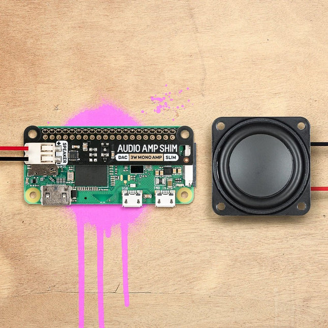
SHIM is een oude Yorkshire term die 'Shove Hardware In Middle' betekent - wij gebruiken het voor Raspberry Pi add-ons die zijn ontworpen om tussen uw Pi en een HAT of mini HAT te worden geklemd. Deze heeft een slimme friction fit header die gemakkelijk over je GPIO pinnen glijdt, niet gesoldeerd hoeft te worden*, en gemakkelijk te verwijderen is.De MAX98357A gecombineerde DAC/versterker-chip neemt digitale audio van hoge kwaliteit van uw Pi en versterkt deze, zodat deze kan worden gebruikt met een luidspreker zonder voeding. De push-fit connectors maken het eenvoudig om uw luidspreker aan te sluiten, of het nu een boekenplank of vloerstaande luidspreker is, de luidspreker in een oude radio, of een andere luidspreker die u misschien heeft liggen. Omdat Audio Amp SHIM geen extra ruimte toevoegt aan uw Pi, is het perfect om in te bouwen in een compacte behuizing - u kunt het gebruiken om een kleine MP3-speler te maken om lokale bestanden af te spelen of te streamen van diensten zoals Spotify, een vintage radio de mogelijkheid te geven om digitale radiostreams af te spelen of bliepgeluiden te integreren in uw eigen retro handheld. Het is ook een handige manier om audio-uitgang aan uw Pi Zero of Pi 400 toe te voegen!Let op: Raspberry Pi and speakers zijn niet inbegrepen bij dit board. Features
MAX98357A DAC / amplifier chip
Mono 3W audio out
Push-fit speaker terminals
SHIM-format board with friction-fit connectors
2x mounting holes (M2.5) for if you want to secure everything together with bolts
Fully-assembled
No soldering required (*unless you're using a Pi that comes without a header)
Compatible with all 40-pin header Raspberry Pi models
SoftwareDe eenvoudigste manier om alles in te stellen is gebruik te maken van Pimoroni's Pirate Audio software en installer die I2S audio configureert, alsook Mopidy installeert en onze aangepaste Pirate Audio plugins waarmee u Spotify kunt streamen en lokale bestanden kunt afspelen.Hier is hoe te beginnen:
Stel een SD-kaart in met de laatste versie van Raspberry Pi OS.
Maak verbinding met Wi-Fi of een bekabeld netwerk.
Open een terminal en type het volgende:git clone https://github.com/pimoroni/pirate-audiocd pirate-audio/mopidysudo ./install.sh
Reboot your Pi
Downloads
MAX98357A Datasheet
Pirate Audio software
Schematic
De SparkFun Qwiic OpenLog is de slimmere en beter uitziende neef van de extreem populaire OpenLog, maar nu hebben we de originele serieel gebaseerde interface overgezet naar I²C! Dankzij de toegevoegde Qwiic connectoren, kunt u meerdere I²C apparaten doorlussen en ze allemaal loggen zonder uw seriële poort in beslag te nemen. De Qwiic OpenLog kan enorme hoeveelheden seriële data opslaan, of 'loggen', en fungeren als een soort zwarte doos om alle data op te slaan die uw project genereert, voor wetenschappelijke of debugging doeleinden. Door gebruik te maken van ons handige Qwiic systeem, hoeft u niet te solderen om het aan te sluiten op de rest van uw systeem. We hebben echter nog steeds 0,1'-spaced pinnen voor het geval u liever een breadboard gebruikt. Net als zijn voorganger, loopt de SparkFun Qwiic OpenLog op een ATmega328, die op 16 MHz draait dankzij de resonator aan boord. De ATmega328 is zeker om te beschikken over de Optiboot bootloader geladen, waardoor de OpenLog compatibel te zijn met de 'Arduino Uno' board instelling in de Arduino IDE. Het is belangrijk om ervan bewust te zijn dat de Qwiic OpenLog ongeveer 2 mA-6 mA trekt in idle (niets op te nemen) modus, echter, tijdens een volledige opname kan de OpenLog 20 mA tot 23 mA trekken, afhankelijk van de microSD-kaart die wordt gebruikt. De Qwiic OpenLog ondersteunt ook clock stretching, wat betekent dat het nog beter presteert dan het origineel en gegevens zal opnemen tot 20.000 bytes per seconde bij 400 kHz. Als de ontvangst buffer vol raakt zal deze OpenLog de klok lijn vasthouden, om de master te laten weten dat hij bezig is. Zodra de Qwiic OpenLog klaar is met een taak, geeft het de klok vrij, zodat de gegevens kunnen blijven stromen zonder corruptie. Voor nog betere prestaties is de OpenLog Artemis de tool die u nodig hebt, met logging snelheden tot 500000 bps. Functies Continue datalogging met 20.000 bytes per seconde zonder corruptie Compatibel met hoge-snelheid 400 kHz I²C Compatibel met 64 MB tot 32 GB microSD-kaarten (FAT16 of FAT32) Geladen Uno bootloader zodat het upgraden van de firmware net zo eenvoudig is als het laden van een nieuwe sketch Valid I²C Adressen: 0x08 tot 0x77 2x Qwiic aansluitingen Downloads Schema Eagle-bestanden Aansluithandleiding Arduino-bibliotheek GitHub
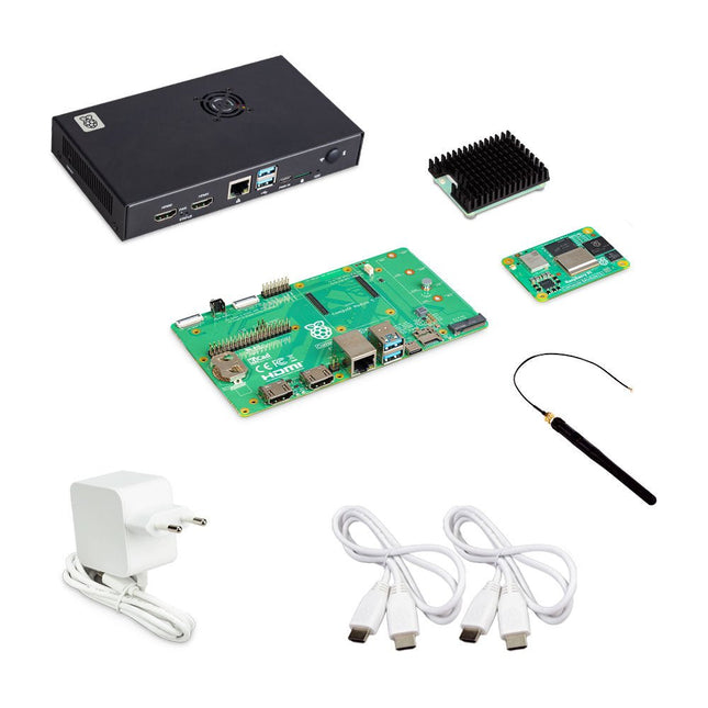
De Raspberry Pi Compute Module 5 Development Kit biedt een ideaal platform voor het prototypen van ingebedde oplossingen. Deze alles-in-één kit bevat de Compute Module 5, het Compute Module 5 IO Board en alle benodigde accessoires om uw productontwerp te starten.
Compute Module 5 (CM5104032)
2,4-GHz quad-core 64-bit Arm Cortex-A76 CPU
VideoCore VII GPU, ondersteunt OpenGL ES 3.1 en Vulkan 1.3
4 GB LPDDR4X-4267 SDRAM
32 GB MLC eMMC-geheugen
1x Dual 4Kp60 HDMI-schermuitgang
1x 4Kp60 HEVC-decoder
1x Dual-band 802.11ac wifi en Bluetooth 5.0
2x USB 3.0-interfaces, die gelijktijdige 5 Gbps-werking ondersteunen
1x Gigabit Ethernet, met IEEE 1588-ondersteuning
2x MIPI-camera/display-zendontvangers met 4 rijstroken
1x PCIe 2.0-interface voor snelle randapparatuur
30 GPIO's, die werking op 1,8 V of 3,3 V ondersteunen
Randapparatuur: UART, SPI, I²C, I²S, SDIO en PWM
Compute Module 5 IO Board
1x Standaard 40-pins GPIO
2x HDMI 2.0 op volledige grootte
2x 4-baans MIPI DSI/CSI-2 FPC (22-pins kabel met een steek van 0,5 mm)
2x USB 3.0
1x Gigabit Ethernet-aansluiting met PoE+ ondersteuning (vereist een aparte Raspberry Pi PoE+ HAT+)
1x M.2 M-key PCIe-socket (voor 2230, 2242, 2260 en 2280 modules)
1x microSD-kaartsleuf (voor gebruik met Lite-modules)
1x RTC-batterijaansluiting
1x 4-pins ventilatorconnector
Compute Module 5 IO-behuizing
De metalen behuizing transformeert het IO Board in een volledig gesloten computer van industriële kwaliteit. De IO-behuizing is speciaal ontworpen voor de Raspberry Pi Compute Module 5 en beschikt over een ingebouwde ventilator die wordt aangesloten op de 4-pins ventilatorconnector van het IO Board, waardoor verbeterde thermische prestaties worden gegarandeerd.
Inbegrepen
1x Raspberry Pi Compute Module 5 (Wireless, 4 GB RAM, 32 GB eMMC)
1x Raspberry Pi Compute Module 5 IO Board (voorgemonteerd geleverd in de IO-behuizing)
1x Raspberry Pi Compute Module 5 IO-behuizing
1x Raspberry Pi Compute Module 5 koeler
1x Raspberry Pi antennekit
1x Raspberry Pi 27 W USB-C PD voeding (EU)
2x Raspberry Pi HDMI naar HDMI-kabels
1x Raspberry Pi USB-A naar USB-C kabel
Downloads
Datasheet (Compute Module 5)
Datasheet (IO Board)
Datasheet (IO Case)
Datasheet (Cooler)
Datasheet (Antenna Kit)
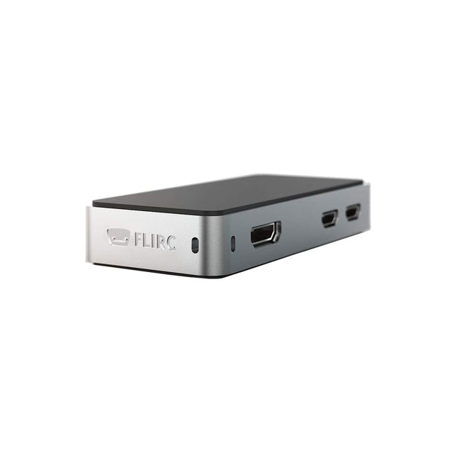
The FLIRC Raspberry Pi Zero Case is compatible with Raspberry Pi Zero W and the newer Raspberry Pi Zero 2 W.
The design of the FLIRC Zero Case is based on the original FLIRC case. As with the original, the aluminum housing serves as protection and, thanks to the contact point on the processor, as a passive cooler. Ideal for silent operation.
In addition to a normal cover that encloses and protects the Raspberry Pi Zero, there is a second cover that allows access to the GPIO pins through a small opening.
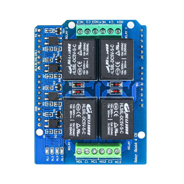
Enhance your Arduino projects with the Ardi Relay Shield, a versatile 4-channel optoisolated relay board. Designed to handle AC (250 V, 7 AMP) and DC (30 V, 10 AMP) power, this shield empowers you to easily control a wide range of electrical devices.
Equipped with four LED relay indicators, the Ardi Relay Shield provides visual feedback on the status of each relay, ensuring you stay informed and in control of your circuit. The shield also features four 3-pin screw terminals (NC, NO, COM) for convenient and secure connections.
Designed in the Arduino form factor, this shield seamlessly integrates with your Arduino Uno, allowing you to expand its capabilities and create interactive projects. Whether you're automating home appliances, building intelligent systems, or working on industrial applications, the Ardi Relay Shield is the reliable choice for robust and efficient relay control.
Features
4-channel optoisolated relay so better electrical isolation between High and Low side voltage.
4x Relay shield compatible with both 3.3 V and 5 V MCU
Onboard 4 Status LED to indicate each relay ON/OFF State
High-quality relays
Provides NO/NC interfaces with Screw terminals.
Mounts directly onto ArdiPi, Ardi32 or other Arduino compatible boards
Specifications
Max Switching Voltage: 250 V AC/30 V DC
Max Switching Current: 7 A/10 A
Max Switching Power: 2770 VA/240 W
Frequency: 1 Hz
Initial Contact Resistance: 50 m? max at 6 V DC/1 A
Operate Time: 10ms max
Release Time: 5ms max
Life Expectancy Electrical: 100,000 operations (rated load)
Life Expectancy Mechanical: 10,000,000 operations (no load)
This board is an all-digital conversion of Raspberry Pi's VGA reference design, great for if you want to start hacking on video and/or audio output from a Raspberry Pi Pico and piping it straight into a modern monitor.Features
HDMI connector
PCM5100A DAC for line out audio over I²S (datasheet)
SD card slot
Reset button
Socket headers to install your Raspberry Pi Pico
Three user-controllable switches
Rubber feet
Compatible with Raspberry Pi Pico
No soldering required (as long as your Pico has header pins attached)
Programmable with C/C++
Note: Raspberry Pi Pico is not included. Your Pico will need to have pin headers soldered to it (with the pins pointing downwards) to attach to our add-on boards.Downloads
Schematic
GitHub
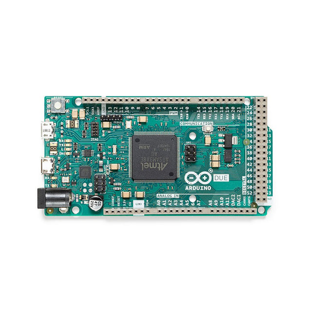
Het board bevat alles wat nodig is om de microcontroller te ondersteunen; sluit hem eenvoudig aan op een computer met een micro-USB-kabel of gebruik een AC / DC-adapter of batterij om aan de slag te gaan. De Due is compatibel met alle Arduino-shields die werken op 3,3V en voldoen aan de 1.0 Arduino-pinout.
De Due volgt de 1.0 pinout:
TWI: SDA- en SCL-pinnen die zich in de buurt van de AREF-pin bevinden.
IOREF: zorgt ervoor dat een aangesloten shield met de juiste configuratie kan worden aangepast aan de spanning die door het board wordt geleverd. Dit maakt shield-compatibiliteit mogelijk met een 3,3V-board zoals de Due- en AVR-gebaseerde kaarten die op 5V werken.
Een niet-verbonden pin, gereserveerd voor toekomstig gebruik.
Specificaties
Werkspanning
3,3 V
Ingangsspanning
7-12 V
Digitale I/O
54
Analoge ingangspennen
12
Analoge uitgangspinnen
2 (DAC)
Totale DC-uitgangsstroom op alle I/O-lijnen
130 mA
DC uitgangsstroom per I/O-pin
20 mA
DC uitgangsstroom voor 3,3 V-pin
800 mA
DC uitgangsstroom voor 5 V-pin
800 mA
Flash-Memory
512 KB geheel beschikbaar voor de gebruikerstoepassingen
SRAM
96 KB
Kloksnelheid
84 MHz
Lengte
101,52 mm
Breedte
53,3 mm
Gewicht
36 g
Opmerking: In tegenstelling tot de meeste Arduino-boards, werkt het Arduino Due-board op 3,3 V. De maximale spanning die de I/O-pinnen kunnen tolereren is 3,3V. Bij het toepassen van spanningen hoger dan 3,3 V op een I/O-pin kan het board beschadigen.
Deze robuuste, passieve aluminium koelbehuizing is speciaal gemaakt voor de Raspberry Pi 5 en biedt een strak ontwerp dat zowel duurzaamheid als effectieve warmteafvoer garandeert. De behuizing is exclusief compatibel met de Raspberry Pi 5 en biedt een passieve koeloplossing, waardoor er geen ventilator meer nodig is en de warmte toch efficiënt wordt beheerd.
Kenmerken
Hoogwaardige aluminium constructie: Deze behuizing is gemaakt van hoogwaardig aluminium en is gebouwd om lang mee te gaan en bestand te zijn tegen regelmatig gebruik.
Geoptimaliseerde warmteafvoer: Het passieve koelingsontwerp maakt gebruik van de aluminium structuur om uw Raspberry Pi 5 koel te houden zonder dat er een ventilator nodig is.
Volledige poorttoegankelijkheid: Elke poort op de Raspberry Pi 5 is gemakkelijk toegankelijk, van de microSD-kaartsleuf tot USB-, micro-HDMI- en GPIO-poorten.
GPIO-kabelondersteuning: Een gereserveerde interface voor de GPIO-kabel zorgt ervoor dat u deze belangrijke functie kunt blijven gebruiken zonder dat u de behuizing hoeft te verwijderen.
Handige aan/uit-schakelaar: De case heeft een geïntegreerde aan/uit-schakelaar waarmee u uw apparaat aan en uit kunt zetten.
The UT622E handheld LCR meter features powerful functions, high accuracy, fast speed, and long standby time. With a clear and intuitive 2.8-inch TFT LCD display, large-capacity rechargeable battery, and 100 kHz test frequency, the meter can be used for longstanding accurate and convenient measurement in any occasion.
It is suitable for the measurement and screening of inductance, capacitance, and resistance in laboratories, production lines, maintenance points, etc.
Features
Max. test frequency: 100 kHz
Accuracy: 0.1%
Display count: 99999
Max. test rate: 20 times/s
DCR: Yes
Connectivity: Mini-USB
Display: 2.8" TFT LCD
Specifications
Testfrequency
100 Hz, 120 Hz, 1 kHz, 10 kHz, 100 kHz
Test level
0.1 Vmrs, 0.3 Vrms, 1 Vrms
Output impedance
100 Ω
Measurement parameters
Primary: L/C/R/Z/DCRSecondary: D/Q/Θ/ESR
DSR speed test
Fast (20 times/s), medium (5 times/s), or slow (2 times/s)
Range
Auto/Hold
Tolerance range
1%~20%
Equivalent mode
Series/Parallel
Clearing connection
Open/Short circuit
Fuse of test ports
0.1 A/250 V
Communication interface
Mini-USB
MAX reading of primary parameters
99999
MIN resolution
0.0001
Maximum accuracy
0.10%
L
0.00 µH~99.999 H
C
0.00 pF~99.999 mF
Z/R
0.0000 Ω~9.9999 MΩ
ESR
0.0000 Ω~999.99 Ω
D
0.0000~9.9999
Q
0.0000~99999
Θ
-179.9°~179.9°
DCR
0.01 mΩ~20.000 MΩ
Power supply
3.7 V/1800 mAh lithium polymer battery
Display
2.8" TFT LCD (320x240)
Dimensions
93 x 192 x 44 mm
Weight
420 g
Included
UT622E LCR meter
Short circuit board
Four-terminal kelvin test leads
USB cable
Manual
Downloads
Datasheet
Manual
Software
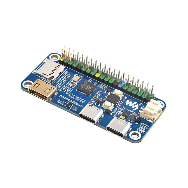
Waveshare RP2040-PiZero is a high-performance and cost-effective microcontroller board with onboard DVI interface, TF card slot and PIO-USB port, compatible with Raspberry Pi 40-pin GPIO header, easy to develop and integrate into the products.
Features
RP2040 microcontroller chip designed by Raspberry Pi
Dual-core ARM Cortex M0+ processor, flexible clock running up to 133 MHz
264 KB of SRAM, and 16 MB of onboard Flash memory
Onboard DVI interface can drive most HDMI screens (DVI compatibility required)
Supports using as a USB host or slave via onboard PIO-USB port
Onboard TF card slot for reading and writing TF card
Onboard Lithium battery recharge/discharge header, suitable for mobile scenarios
USB 1.1 with device and host support
Drag-and-drop programming using mass storage over USB
Low-power sleep and dormant modes
2x SPI, 2x I²C, 2x UART, 4x 12-bit ADC, 16x controllable PWM channels
Accurate clock and timer on-chip
Temperature sensor
Accelerated floating-point libraries on-chip
Downloads
Wiki
Een programmeerbare robotkit met 344 onderdelen
De variAnt loopt en gedraagt zich bijna als zijn natuurlijke evenknie. Het gepatenteerde loopmechanisme is speciaal ontwikkeld om de fijnbenige anatomie van een insect na te bootsen, en wordt aangedreven door compacte micro-motorreductoren.
De autonoom werkende robotmier verkent zelf zijn hele omgeving met behulp van 12 analoge sensoren. Hierdoor kan hij obstakels, markeringen, bewegingen of lichtbronnen detecteren op basis van slechts kleine verschillen in helderheid.
In combinatie met het breadboardje op de kop biedt de besturingseenheid aan de achterzijde, die is uitgerust met een nano-board, een breed scala aan flexibele aansluitmogelijkheden. Nadat de variAnt in elkaar is gezet zorgen kant-en-klare en uitbreidbare modules met codes voor een eenvoudige en snelle introductie van Arduino-programmering en de eerste experimenten met kunstmatige intelligentie.
De kit heeft reeds een USB oplaadbare 9 V Li-Ion accu aan boord die de robotmier minstens 5 uur van stroom kan voorzien.
Robotmier als programmeerbare kit
Compatibel met Arduino IDE
Gepatenteerde mechanica en sensoren
Kenmerken van de variAnt
24 hoogwaardige acryl onderdelen
12 variabele omgevingssensoren
2 reed-sensoren voor stappentelling
2 vrij te programmeren knoppen
8 vrij te gebruiken digitale I/O's
15 insteekbare status LED's
Specificaties
Inhoud: 344 onderdelen
Bouwtijd: ongeveer 4-8 uur (solderen niet nodig)
Afmetingen: 25 x 22,5 x 9 cm (L x B x H)
Gewicht: 210/232 g (zonder/met accu)
Benodigde tools
PC of tablet, micro-USB en USB-C kabel, platte tang, diagonale tang, tapijtmes, permanente marker
Downloads
Manual
Arduino library
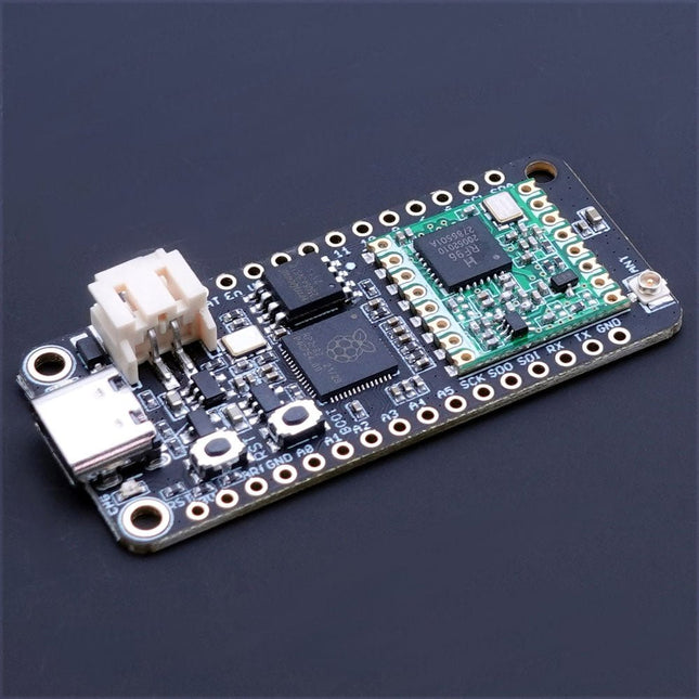
The Challenger RP2040 LoRa is an Arduino/CircuitPython compatible Adafruit Feather format microcontroller board based on the Raspberry Pi Pico (RP2040) chip.The transceiver features a LoRa long range modem that provides ultra-long range spread spectrum communication and high interference immunity whilst minimizing current consumption.LoRaThe integrated module LoRa module (RFM95W) can achieve a sensitivity of over -148 dBm utilizing a low cost crystal and bill of materials. The high sensitivity combined with the integrated +20 dBm power amplifier yields industry leading link budget making it optimal for any application requiring range or robustness. LoRa also provides significant advantages in both blocking and selectivity over conventional modulation techniques, solving the traditional design compromise between range, interference immunity and energy consumption.The RFM95W is connected to the RP2040 via SPI channel 1 and a few GPIO’s that is required for signaling. A U.FL connector is used to attach your LoRa antenna to the board.
168 dB maximum link budget
+20 dBm – 100 mW constant RF output vs. V supply
+14 dBm high efficiency PA
Programmable bit rate up to 300 kbps
High sensitivity: down to -148 dBm
Bullet-proof front end: IIP3 = -12.5 dBm
Excellent blocking immunity
Low RX current of 10.3 mA, 200 nA register retention
Fully integrated synthesizer with a resolution of 61 Hz
FSK, GFSK, MSK, GMSK, LoRaTM and OOK modulation
Built-in bit synchronizer for clock recovery
Preamble detection
127 dB Dynamic Range RSSI
Automatic RF Sense and CAD with ultra-fast AFC
Packet engine up to 256 bytes with CRC
Specifications
Microcontroller
RP2040 from Raspberry Pi (133 MHz dual-core Cortex-M0)
SPI
Two SPI channels configured (second SPI connected to RFM95W)
I²C
One I²C channel configured
UART
One UART channel configured
Analog inputs
4 analog input channels
Radio module
RFM95W from Hope RF
Flash memory
8 MB, 133 MHz
SRAM memory
264 KB (divided into 6 banks)
USB 2.0 controller
Up to 12 MBit/s full speed (integrated USB 1.1 PHY)
JST Battery connector
2.0 mm pitch
On board LiPo charger
450 mA standard charge current
Dimensions
51 x 23 x 3,2 mm
Weight
9 g
Downloads
Datasheet
Design files
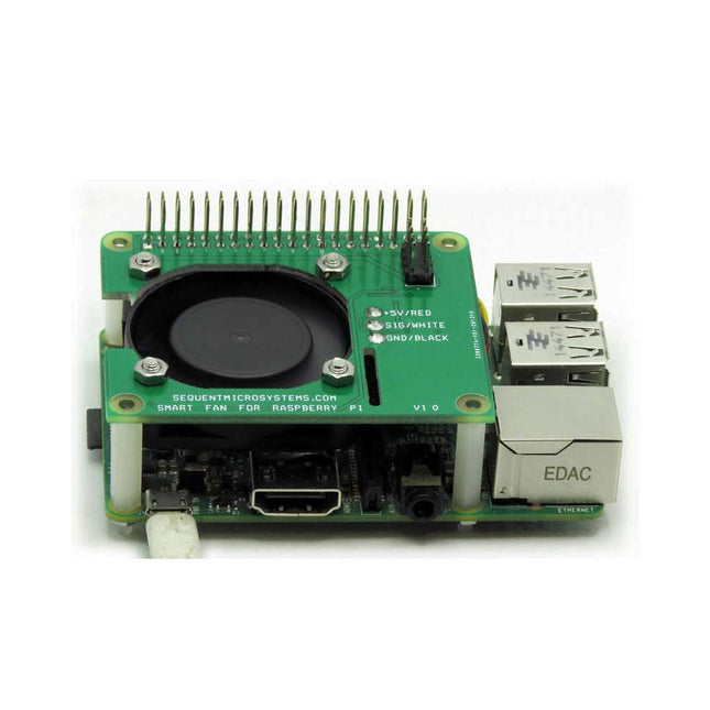
Raspberry Pi 4 was welcomed by the Pi enthusiasts for the increased processing power. However, this came at a price. The RPi 4 can draw up to 3 Amps, which means it has to dissipate 15 W of power. Raspberry Pi cooling is a must. From the simplest passive heat sink, through elaborate fan blowers and even to an exotic water-cooled idea, many options are available.
The Sequent Microsystems Smart Fan has the form factor of the Raspberry Pi HAT. Its own tinny 32-bit processor receives commands from Raspberry Pi through the I²C interface. A step-up power supply converts the 5 V provided by Raspberry Pi to 12 V, ensuring precise speed control. Using pulse width modulation, it powers the fan just enough to maintain a constant temperature of the Raspberry Pi processor.
The Smart Fan preserves all the GPIO pins, allowing any number of cards to be stacked on top of Raspberry Pi. If another add-on card has to dissipate power, a secondary Smart Fan can be added to the stack.
DIN-Rail Mounting
Together with multiple add-on cards, the Smart Fan can be installed on the DIN-Rail, for sturdy industrial applications.
Stack Level Jumper
Two Smart Fans can be installed on top of each Raspberry Pi. The assumption is that you have one more card in the stack which requires cooling. The bottom side of the Smart Fan has a jumper which needs to be installed on the second fan, in order for the Raspberry Pi to differentiate the two I²C addresses.
Features
40 x 40 x 10 mm fan with 6 CFM airflow
Step-up 12 V power supply for precise fan speed control
PWM Controller modulates the fan to keep constant Pi temperature
Draws less than 100 mA of power
Stackable to itself, 2 fans can be added to Raspberry Pi
Fully stackable allows adding other cards to Raspberry Pi
Uses only I²C interface, leaves full use of all GPIO pins
Super quiet and efficient
Included
Smart Fan HAT
40 x 40 x 10 mm Fan with mounting Screws
Mounting Hardware
Downloads
User's Guide
Open Source Hardware Schematic
2D CAD Drawing
Command line
Python Libraries
Node-Red Nodes