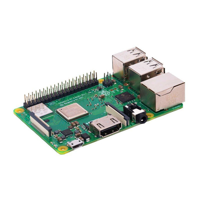
Vergeleken met de eigenschappen van zijn voorganger, zijn de snelheid en het vermogen van deze Raspberry Pi 3 B+ met 15% toegenomen zonder de compatibiliteit (elektrisch en mechanisch) met de Raspberry Pi 3 B, 2 en B+ modellen te belemmeren.
Features
Quad-core processorversnelling: ongeveer 10% meer verwerkingscapaciteit
Ondersteuning voor H.264 MPEG-4, H.264 en Open GL ES 1.1 & 2.0 grafisch beheer
1 GB LPDDR2 SDRAM
802.11ac dual band draadloze communicatie (2,4 GHz/5 GHz)
Power over Ethernet (PoE) mogelijk
Nieuwe Ethernet controller
Verbeterde energiebeheer
Verbeterde thermisch beheer
Nu met WiFi 802.11ac (2.4 GHz/5 GHz)
Verhoogde verbindingssnelheid en bandbreedte
Groter bereik wanneer aangesloten op het 5 GHz-kanaal
Achterwaartse compatibiliteit binnen toepassingen
Verbeterde streaming HD-video via WiFi
Verhoogde effectiviteit als draadloos toegangspunt
Verbeterde rekenprestatie
Snellere core processor (4x 1,4 GHz)
Voeding over Ethernet mogelijk
PoE dankzij de PoE HAT (binnenkort beschikbaar)
De RPi 3 B+ heeft voor zijn voedingsstroom geen stopcontact meer nodig, hij kan ergens ver weg (<100 m) via de ethernet verbinding gevoed worden.
Daardoor worden installatie en distributie van Raspberry Pi netwerken eenvoudiger en effectiever
Nieuwe Ethernet controller
Ethernet van de Raspberry Pi 3 B+ is 3x sneller (~300 Mbps)
Snellere gegevensoverdracht via het netwerk
Specificaties
SoC
Broadcom BCM2837B0 64bit ARMv8 quad-core CPU
CPU
ARM Cortex-A53 (64-bit) quad-core 1400 MHz
GPU
Dual-Core VideoCore IV Multimedia Co-Processor
RAM
1024 MB
USB
4x USB-A 2.0
GPIO
40 Pins
Ethernet
Gigabit Ethernet via USB 2.0
Wireless LAN
802.11b/g/n/ac (2.4 GHz/5 GHz)
Bluetooth
4.2 + LE
Audio/Video
4-polige stereo uitgang / composiete video poort
Aansluitingen
Full size HDMI / CSI camera / DSI display poort / microSD poort (verbeterd)
Voedingsaansluiting
Micro-USB (5 V | < 2,5 A)
Afmetingen
85 x 56 x 17 mm
Met deze 65 W USB-C PD voeding (met GaN technologie) kunt u de FNIRSI HS-01 soldeerbout direct gebruiken. Natuurlijk kunt u deze lader ook gebruiken om uw tablets en smartphones snel op te laden via USB-C en USB-A.
Inbegrepen
65 W USB-C PD GaN Voeding (EU)
De SEQURE HT140 is een zeer veelzijdige 2-in-1 soldeerbout die de functionaliteit van een hete pincet en een soldeerbout combineert. Hij is speciaal ontworpen voor nauwkeurig SMD-soldeer- en desoldeerwerk.
Met onafhankelijke regeling voor enkelzijdige verhitting werkt hij als een traditionele soldeerbout wanneer hij is uitgerust met een standaardpunt. Wanneer hij is geconfigureerd voor dubbelzijdige verhitting, transformeert hij in een hete pincet – perfect voor het efficiënt en nauwkeurig verwijderen van SMD-componenten.
Kenmerken
Werktemperatuur: 50-500°C
Ondersteunt meerdere voedingsingangen: PD 3.1/3.0/2.0, QC 3.0/2.0, (5-28 V DC), LiPo-batterijen en stroomadapters.
De HT140 combineert een soldeerpincet met een soldeerbout, met onafhankelijke enkel- of dubbelzijdige verwarming. Gebruik hem als soldeerbout met een punt, of als soldeerpincet voor eenvoudig desolderen van SMD.
Spanning en stroomsterkte kunnen worden aangepast op basis van de stroombron.
Beschikt over dubbele temperatuurregeling, voorinstellingen, snelle temperatuurverhoging en fijnafstelling.
128 x 32 OLED-scherm met instelbare helderheid en oriëntatie.
Hoognauwkeurig verwarmingselement met een nauwkeurigheid van ±1%. Smelt soldeer in slechts 2 seconden.
Slimme stand-by-, slaap- en wekfuncties verlengen de levensduur van de punt en verhogen de efficiëntie.
Ondersteunt temperatuurkalibratie en -compensatie voor nauwkeurig werk.
Inclusief een hittebestendige PD 150 W siliconenkabel van 1,5 m en een stevig, volledig metalen HT-station.
Verwisselbare punten en verstelbare hoeken voor diverse SMD-soldeertaken.
Specificaties
Werkspanning
5-28 V DC
Maximaal vermogen
140 W
Werktemperatuur
50-500°C
Smelttijd tin
2 s
Interfacetype
USB-C, DC5525
Voeding
PD 3.1/3.0/2.0, QC 3.0/2.0, 28 V DC max
Display
128 x 32 OLED
Firmware-upgrade
Ja
Menutalen
Engels, Russisch, Chinees
Afmetingen
160 x 27 x 17,5 mm
Gewicht
50 g
Inbegrepen
1x SEQURE HT140 Host
2x HT140-IS Conisch gebogen desoldeerstiften
1x HT Station
1x Accessoirepakket
1x Opbergtas
1x 65 W PD Voeding (EU, VK & VS)
1x 24 W PD Siliconen Draad (1,5 m)
1x GND Draad Accessoire Kit (1,8 m)
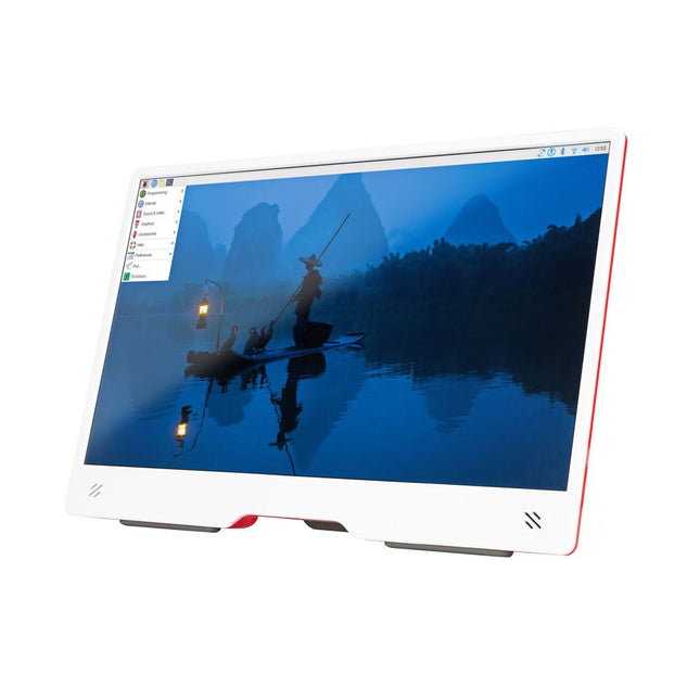
De Raspberry Pi Monitor is een 15,6-inch Full HD-computerscherm. Gebruiksvriendelijk, veelzijdig, compact en betaalbaar, het is de perfecte desktop-displaygenoot voor zowel Raspberry Pi-computers als andere apparaten.
Met ingebouwde audio via twee naar voren gerichte luidsprekers, VESA- en schroefmontagemogelijkheden en een geïntegreerde in hoek verstelbare standaard is de Raspberry Pi Monitor ideaal voor desktopgebruik of voor integratie in projecten en systemen. Hij kan rechtstreeks van een Raspberry Pi worden voorzien, of via een aparte voeding.
Kenmerken
15,6-inch Full HD 1080p IPS-scherm
Geïntegreerde in hoek verstelbare standaard
Ingebouwde audio via twee naar voren gerichte luidsprekers
Audio-uitgang via 3,5 mm-aansluiting
HDMI-ingang op volledige grootte
VESA- en schroefmontageopties
Volume- en helderheidsknoppen
USB-C-voedingskabel
Specificaties
Display
Schermgrootte: 15,6 inch, verhouding 16:9
Paneeltype: IPS LCD met antireflectiecoating
Weergaveresolutie: 1920 x 1080
Kleurdiepte: 16,2M
Helderheid (typisch): 250 nits
Kleurgamma: 45%
Kijkhoek: 80°
Voeding
1,5 A/5 V
Kan rechtstreeks worden gevoed via een Raspberry Pi USB poort (max 60% helderheid, 50% volume) of via een aparte voeding (max 100% helderheid, 100% volume)
Connectiviteit
Standaard HDMI-poort (compatibel met 1.4)
3,5 mm stereohoofdtelefoonaansluiting
USB-C (voeding in)
Audio
2x 1,2 W geïntegreerde luidsprekers
Ondersteuning voor bemonsteringsfrequenties van 44,1 kHz, 48 kHz en 96 kHz
Downloads
Datasheet
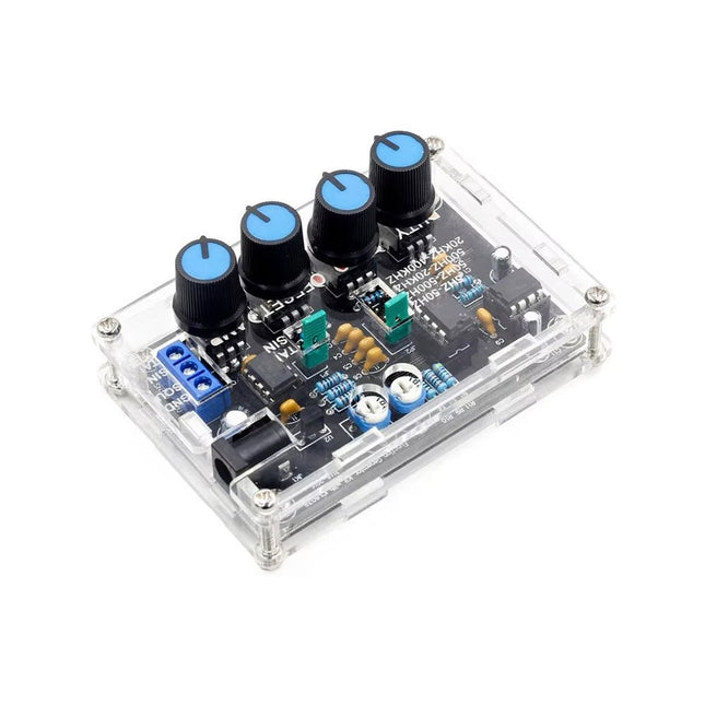
De ICL8038-signaalgenerator levert veelzijdige golfvormen, waaronder sinus, driehoek, vierkant en voorwaartse/achterwaartse zaagtand, waardoor hij geschikt is voor een breed scala aan toepassingen. Aangedreven door de ICL8038-chip en snelle operationele versterkers, zorgt het voor uitzonderlijke precisie en signaalstabiliteit.
Met een frequentiebereik van 5 Hz tot 400 kHz ondersteunt het toepassingen van audio- tot radiofrequenties. De instelbare werkcyclus, variërend van 2% tot 95%, maakt nauwkeurige aanpassing van de golfvorm mogelijk om aan verschillende behoeften te voldoen.
De DIY-kit is beginnersvriendelijk en bevat componenten met doorlopende gaten voor eenvoudige montage. Het bevat alle benodigde onderdelen, een acrylomhulsel en een gedetailleerde handleiding, die alles biedt wat nodig is om de signaalgenerator efficiënt te bouwen en te gebruiken.
Specificaties
Frequentiebereik
5 Hz~400 KHz (instelbaar)
Voedingsspanning
12 V~15 V
Bereik van de werkcyclus
2%~95% (instelbaar)
Sinusgolf met lage vervorming
1%
Lage temperatuurafwijking
50 ppm/°C
Uitvoer van driehoekige golflineariteit
0,1%
DC-biasbereik
−7,5 V~7,5 V
Uitgangsamplitudebereik
0,1 V~11 VPP (werkspanning 12 V)
Afmetingen
89 x 60 x 35 mm
Gewicht
81 g
Inbegrepen
PCB incl. alle benodigde componenten
Acrylbehuizing
Manual
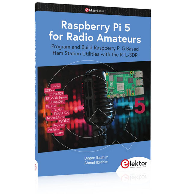
Program and Build Raspberry Pi 5 Based Ham Station Utilities with the RTL-SDR
The RTL-SDR devices (V3 and V4) have gained popularity among radio amateurs because of their very low cost and rich features. A basic system may consist of a USB based RTL-SDR device (dongle) with a suitable antenna, a Raspberry Pi 5 computer, a USB based external audio input-output adapter, and software installed on the Raspberry Pi 5 computer. With such a modest setup, it is possible to receive signals from around 24 MHz to over 1.7 GHz.
This book is aimed at amateur radio enthusiasts and electronic engineering students, as well as at anyone interested in learning to use the Raspberry Pi 5 to build electronic projects. The book is suitable for both beginners through experienced readers. Some knowledge of the Python programming language is required to understand and eventually modify the projects given in the book. A block diagram, a circuit diagram, and a complete Python program listing is given for each project, alongside a comprehensive description.
The following popular RTL-SDR programs are discussed in detail, aided by step-by-step installation guides for practical use on a Raspberry Pi 5:
SimpleFM
GQRX
SDR++
CubicSDR
RTL-SDR Server
Dump1090
FLDIGI
Quick
RTL_433
aldo
xcwcp
GPredict
TWCLOCK
CQRLOG
klog
Morse2Ascii
PyQSO
Welle.io
Ham Clock
CHIRP
xastir
qsstv
flrig
XyGrib
FreeDV
Qtel (EchoLink)
XDX (DX-Cluster)
WSJT-X
The application of the Python programming language on the latest Raspberry Pi 5 platform precludes the use of the programs in the book from working on older versions of Raspberry Pi computers.
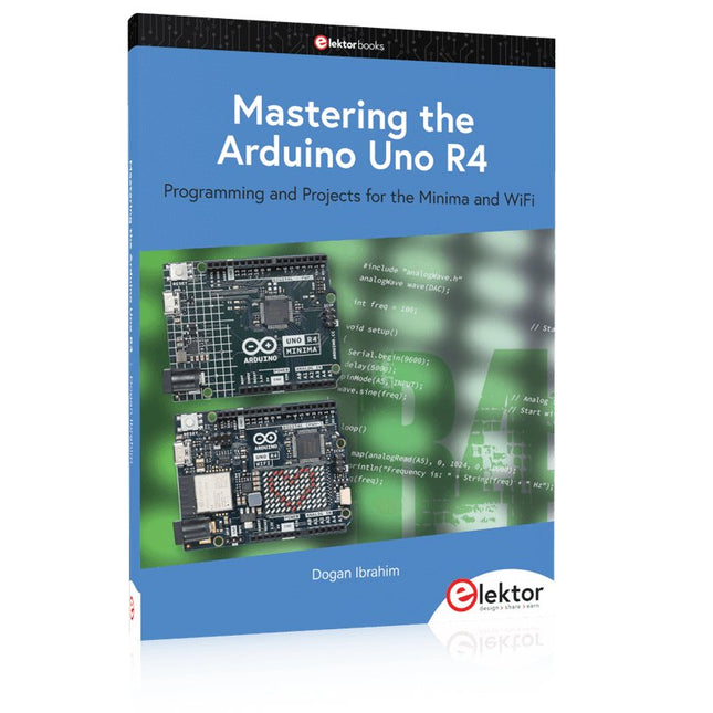
Programming and Projects for the Minima and WiFi
Based on the low-cost 8-bit ATmega328P processor, the Arduino Uno R3 board is likely to score as the most popular Arduino family member, and this workhorse has been with us for many years. Eleven years later, the long-overdue successor, the Arduino Uno R4, was released. It is built around a 48 MHz, 32-bit Arm Cortex-M4 microcontroller and provides significantly expanded SRAM and Flash memory. Additionally, a higher-precision ADC and a new DAC are added to the design. The Uno R4 board also supports the CAN Bus with an interface.
Two versions of the board are available: Uno R4 Minima, and Uno R4 WiFi. This book is about using these new boards to develop many different and interesting projects with just a handful of parts and external modules. All projects described in the book have been fully tested on the Uno R4 Minima or the Uno R4 WiFi board, as appropriate.
The project topics include the reading, control, and driving of many components and modules in the kit as well as on the relevant Uno R4 board, including
LEDs
7-segment displays (using timer interrupts)
LCDs
Sensors
RFID Reader
4x4 Keypad
Real-time clock (RTC)
Joystick
8×8 LED matrix
Motors
DAC (Digital-to-analog converter)
LED matrix
WiFi connectivity
Serial UART
CAN bus
Infrared controller and receiver
Simulators
… all in creative and educational ways with the project operation and associated software explained in great detail.
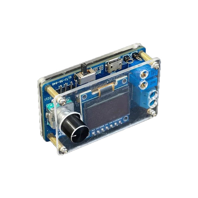
De DIY Mini Digitale Oscilloscoop Kit (met behuizing) is een eenvoudig te bouwen bouwpakket voor een kleine digitale oscilloscoop. Naast de aan/uit-schakelaar heeft het slechts één andere regelaar, een roterende encoder met een ingebouwde drukknop. De microcontroller van de kit is voorgeprogrammeerd. Het OLED-scherm van 0,96" heeft een resolutie van 128 x 64 pixels. De oscilloscoop heeft één kanaal dat signalen tot 100 kHz kan meten. De maximale ingangsspanning is 30 V, de minimale spanning is 0 V.
De kit bestaat uit through-hole componenten (THT) en surface-mount devices (SMD). Daarom betekent het in elkaar zetten van de kit het solderen van SMD-onderdelen, waarvoor enige soldeerervaring nodig is.
Specificaties
Verticaal bereik: 0 tot 30 V
Horizontaal bereik: 100 µs tot 500 ms
Triggertype: Automatisch, Normaal en Single
Triggerflank: Stijgen en dalen
Triggerniveau: 0 tot 30 V
Run/Stop-modus
Automatische frequentiemeting
Voeding: 5 V micro-USB
10 Hz, 5 V sinusgolfuitgang
9 kHz, 0 tot 4,8 V blokgolfuitgang
Weergave: 0,96-inch OLED-scherm
Afmetingen: 57 x 38 x 26 mm
Downloads
Documentation
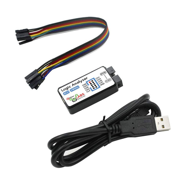
Deze USB Logic Analyzer is een 8-kanaals logic analyzer met elke ingang bedoeld voor het op twee manieren opnemen van analoge data. Hij is perfect voor het debuggen en analyseren van signalen zoals I²C, UART, SPI, CAN en 1-Wire. De analyzer bemonstert een digitale ingang die is aangesloten op een te testen apparaat (DUT) met een hoge bemonsteringssnelheid. De aansluiting op de PC gaat via USB.Specificaties
Kanalen
8 digitale kanalen
Maximale bemonsteringssnelheid
24 MHz
Maximale ingangsspanning
0 V ~ 5 V
Bedrijfstemperatuur
0°C ~ 70°C
Ingangsimpedantie
1 MΩ || 10 pF
Ondersteunde protocollen
I²C, SPI, UART, CAN, 1-wire, enz.
PC-aansluiting
USB
Afmetingen
55 x 28 x 14 mm
Inbegrepen
USB Logic Analyzer (8-kanaals, 24 MHz)
USB-kabel
Jumper Draad Lintkabel
DownloadsSoftware
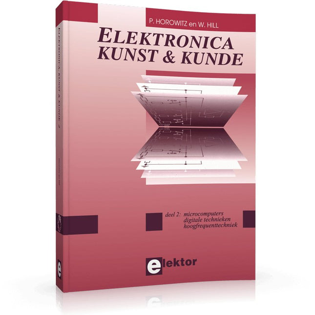
In Elektronica Kunst & Kunde worden alle onderwerpen behandeld die ook in standaard elektronica-leerboeken aan de orde komen, plus een groot aantal belangrijke maar vaak veronachtzaamde zaken.
In dit tweede deel aandacht voor onder meer de volgende onderwerpen:
phase-locked loop-schakelingen, opto-elektronica, busschakelingen, capacitieve belasting, bekabeling, interfacing
timing, naaldpulsen, klokvertraging, monostabiele multivibratoren
de IBM-PC en de Intel-fanilie, RS232-kabels, seriële poorten, ASCII, modems, SCSI, IPI, GPIB, parallele poorten, local-area-networks
de 68000-microprocessorfamilie, perifere LSI-chips, geheugen, programmeerbare instrumenten
prototypering, het ontwerpen van printplaten, wire-wrap-technieken, CAD/CAM technieken, de bouw van schakelingen
HF-modules, vereenvoudigd ontwerp van HF-versterkers en high-speed schakelaars
batterijen, accu's en zonnecellen; micropower-regelaars, -opamps en -microprocessoren
methoden om de bandbreedte te beperken, middeling van signalen, lock-in versterkers, pulshoogte-analyse, 'multichannel-scaling'
Program, build, and master over 60 projects with Python
The Raspberry Pi 5 is the latest single-board computer from the Raspberry Pi Foundation. It can be used in many applications, such as in audio and video media centers, as a desktop computer, in industrial controllers, robotics, and in many domestic and commercial applications. In addition to the well-established features found in other Raspberry Pi computers, the Raspberry Pi 5 offers Wi-Fi and Bluetooth (classic and BLE), which makes it a perfect match for IoT as well as in remote and Internet-based control and monitoring applications. It is now possible to develop many real-time projects such as audio digital signal processing, real-time digital filtering, real-time digital control and monitoring, and many other real-time operations using this tiny powerhouse.
The book starts with an introduction to the Raspberry Pi 5 computer and covers the important topics of accessing the computer locally and remotely. Use of the console language commands as well as accessing and using the desktop GUI are described with working examples. The remaining parts of the book cover many Raspberry Pi 5-based hardware projects using components and devices such as
LEDs and buzzers
LCDs
Ultrasonic sensors
Temperature and atmospheric pressure sensors
The Sense HAT
Camera modules
Example projects are given using Wi-Fi and Bluetooth modules to send and receive data from smartphones and PCs, and sending real-time temperature and atmospheric pressure data to the cloud.
All projects given in the book have been fully tested for correct operation. Only basic programming and electronics experience are required to follow the projects. Brief descriptions, block diagrams, detailed circuit diagrams, and full Python program listings are given for all projects described.
De FNIRSI SWM-20 handlasmachine is een zeer efficiënt, gebruiksvriendelijk en gemakkelijk mee te nemen lasapparaat. Hij is voorzien van dual-pulse puntlastechnologie, wat zorgt voor stabielere en betrouwbaardere lassen, en beschikt bovendien over een handige powerbankfunctie.
Uitgerust met een 2,4-inch HD-display biedt de SWM-20 een duidelijke en intuïtieve bediening. Met de draaiknop kunnen gebruikers parameters snel en nauwkeurig aanpassen, waardoor het eenvoudig is om de gewenste lasinstellingen te kiezen en de algehele gebruikerservaring te verbeteren.
Kenmerken
2-in-1: Puntlasapparaat en 5000 mAh powerbank
1200 A hoog vermogen voor sterke, betrouwbare lassen
Dual-Pulse technologie voor schoner en stabieler lassen
Twee A-klasse accu's met 8 veiligheidsfuncties
Lasmogelijkheid voor meerdere materialen van 0,1–0,5 mm
Meer dan 10.000 precisie-instelniveaus voor professionele controle
2,4-inch TFT-display met realtime gegevensbewaking
Specificaties
Maximale lasstroom
1200 A
Batterijcapaciteit
5000 mAh
Opladen
5 V/2,1 A
Ontladen
5 V/2,1 A
Lasmaterialen
Nikkel, ijzer, roestvrij staal
Lasdikte
0,1-0,5 mm
Niveau
4 vooraf ingestelde combinaties Niveaus
Inbegrepen
1x FNIRSI SWM-20 puntlasapparaat
2x Laspennen
2x Vervangingstips
1x Nikkelstrip
1x USB-C kabel
1x Manual
Downloads
Manual
From SRPP and Mu-Follower to OTL Designs
Tube amplifiers suffer from distortion. Fortunately, circuits such as the SRPP amplifier, mu-follower, and beta-follower produce minimal distortion even at output voltages of 50 to 100 Vpeak.
These designs are often published with errors. Without a sound understanding of the theory, it is easy to arrive at a flawed design.
In the first section of this book, we investigate the origin of distortion, while in the second we investigate the design of and SRPP and a mu-follower.
On the internet we can find the most exotic designs. Evaluating them teaches us that these designs often make matters worse rather than better. In the chapter on incorrect SRPPs and mu-followers, we sometimes see bizarre and misguided designs where using a simple single-triode amplifier would perform much better.
Push-pull output stages also exist. A great number of them are examined, and their similarity to the SRPP is discussed. This is done especially with the help of the theory behind the OTL based on the ‘mother’ of all OTLs, the Philips HF303.
Finally, attention is given to frequency characteristics and technical matters such as the supply voltage and the filament power supply.
To illustrate these points, there are a few designs covering the subjects discussed.
This book presents much new theory that has not been published before. It is often an eye-opener, showing that many things have a beautiful and unexpected simplicity.
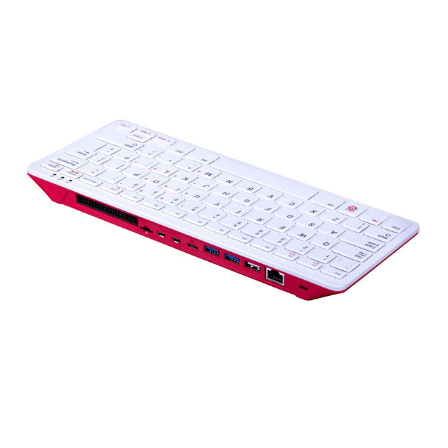
De Raspberry Pi 400 biedt een quad-core 64-bits processor, 4 GB RAM, draadloos netwerken, uitvoer op twee schermen, 4K-videoweergave en een 40-pins GPIO-header. Het is een krachtige, compacte computer ingebouwd in een draagbaar toetsenbord.
Specificaties
Processor
Broadcom BCM2711 quad-core Cortex-A72 (ARM v8) 64-bit SoC @ 1.8 GHz
RAM
4 GB LPDDR4-3200
Connectivity
Dual-band (2.4 GHz and 5.0 GHz) IEEE 802.11b/g/n/ac wireless LANBluetooth 5.0, BLEGigabit Ethernet2 × USB 3.0 and 1 × USB 2.0 ports
GPIO
Horizontal 40-pin GPIO header
Video & Sound
2 × micro HDMI ports (supports up to 4Kp60)
Multimedia
H.265 (4Kp60 decode)H.264 (1080p60 decode, 1080p30 encode)OpenGL ES 3.0 graphics
SD card support
MicroSD card slot for operating system and data storage
Keyboard
US keyboard
Power
5 V DC via USB connector
Operating temperature
0°C to +40°C
Dimensions
286 × 122 × 23 mm (maximum)
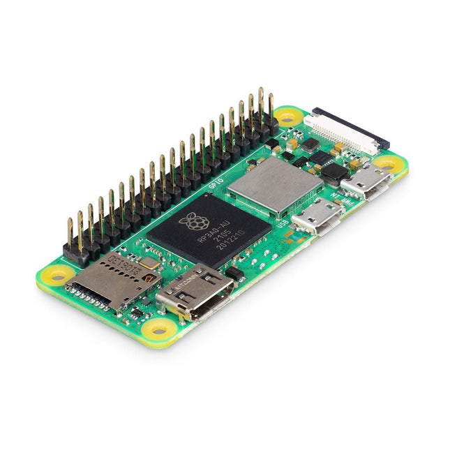
Raspberry Pi Zero 2 WH is de opvolger van de baanbrekende Raspberry Pi Zero W(H). Het bord bevat een quad-core 64-bit Arm Cortex-A53 CPU, geklokt op 1 GHz. Het hart is een Raspberry Pi RP3A0 system-in-package (SiP), waarin een Broadcom BCM2710A1 chip is geïntegreerd met 512 MB LPDDR2 SDRAM. De verbeterde processor biedt Raspberry Pi Zero 2 WH 40% meer single-threaded prestaties, en vijf keer meer multi-threaded prestaties, dan de originele single-core Raspberry Pi Zero.
Kenmerken
64-bit quad core-processor
VideoCore IV GPU
512 MB LPDDR2 DRAM
802.11b/g/n draadloos LAN
Bluetooth 4.2 / Bluetooth Low Energy (BLE)
Slot voor MicroSD-kaart
Mini HDMI- en USB 2.0 OTG-poorten
Micro-USB-voeding
Met gemonteerde 40-pins header
Composiet video- en reset-pinnen via soldeer testpunten
CSI-cameraconnector
Specificaties
SoC
Broadcom BCM2710A1
CPU
64-bit ARM Cortex-A53 (4x 1 GHz)
GPU
Broadcom VideoCore VI
RAM
512 MB LPDDR2
Wireless LAN
2,4 GHz IEEE 802.11b/g/n
Bluetooth
Bluetooth 4.2, BLE
USB
1x micro USB (voor data)1x micro USB (voor voeding)
GPIO
HAT-compatibele 40-pins GPIO-header
Video & audio
1080P HD-video en stereo-audio via mini-HDMI-connector
SD-kaart
microSD (voor besturingssysteem en opslag)
Voeding
5 VDC / 2,5 A (geleverd via micro-USB-connector)
Afmetingen
65 x 30 x 5 mm
Raspberry Pi Zero 2 WH is footprint-compatibel met eerdere Zero-modellen.
Bespaar € 10 met deze starterkit in vergelijking met afzonderlijke aankoop!
Deze speciale Raspberry Pi 4 starterkit bevat alles wat je nodig hebt om meteen aan de slag te gaan met 's werelds populairste minicomputer als ontwikkel- en multimedia-apparaat.
Inhoud van de kit
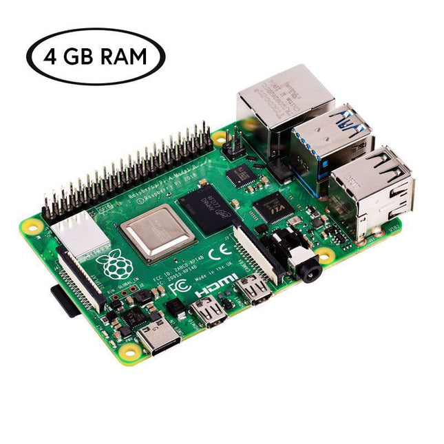
Raspberry Pi 4 B (4 GB RAM)De Raspberry Pi 4 is een compleet computersysteem in een klein formaat dat multimedia en desktop prestaties levert die vergelijkbaar zijn met die van een basis x86 PC systeem.
Broadcom BCM2711 SoC 64-bit quad-core ARM Cortex-A72 (1,5 GHz)
VideoCore VI @ 500 MHz
4 GB LPDDR4 SDRAM
Gigabit Ethernet
802.11ac Wi-Fi
Bluetooth 5.0
2x USB 3.0, 2x USB 2.0 en 1x USB-C (voor stroomvoorziening)
2x micro-HDMI (tot 4Kp60)
1x MicroSD (voor opslag)
Officiële EU voeding (5,1 V, 3 A) voor Raspberry Pi 4 (wit)De officiële Raspberry Pi USB-C voeding (15,3 W) is speciaal ontworpen om de Raspberry Pi 4 van stroom te voorzien.
MicroSD kaart (32 GB, klasse 10) met SD adapter (voorgeïnstalleerd met NOOBS)Deze microSD met voorgeïnstalleerde NOOBS (New Out Of Box Software) is een eenvoudig te gebruiken installatiemanager voor het besturingssysteem van de Raspberry Pi.
Officiële behuizing voor (wit/rood)Deze perfect passende behuizing beschermt de Raspberry Pi 4.
Officiële HDMI kabel voor Raspberry Pi 4 (wit, 1 m)De officiële Raspberry Pi micro-HDMI naar HDMI (A/M) kabel (wit, 1 m) is ontworpen voor de Raspberry Pi 4.
Koellichaamset voor Raspberry PiDeze aluminium koellichamen koelen het board en voorkomen dat de Raspberry Pi oververhit raakt.
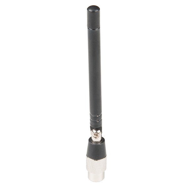
De ANT700 van Great Scott Gadgets is een lichtgewicht telescoopantenne voor gebruik tussen 300 MHz en 1100 MHz. De totale lengte kan worden ingesteld tussen 9,5 cm en 24,5 cm. De ANT700 is gemaakt van roestvrij staal en heeft een SMA-connector, een draaibare schacht en een verstelbaar kniestuk.
De ANT700 is een 50-ohm antenne voor algemeen gebruik. Het is een perfecte instapantenne voor gebruik met HackRF One/Pro.
De Andonstar AD409 Max-ES heeft een hoogwaardige metalen lens en een uniek UV-filterontwerp. Het is gemaakt van hoogwaardige materialen van industriële kwaliteit en levert ongeëvenaarde precisie en duurzaamheid, waardoor een betrouwbare productervaring wordt gegarandeerd. Het UV-filter dat voor de metalen lens is geplaatst, blokkeert soldeerhitte, rook en stof, beschermt de lens en maakt hem perfect voor soldeer- en onderhoudsprofessionals.
De AD409 Max-ES is voorzien van een extra groot Max-station (46 x 37 x 47,5 cm) en een geavanceerde gereedschapsset, waardoor het soldeerstationoppervlak met 370% wordt uitgebreid. Deze upgrade voldoet aan de eisen van professionele soldeerwerkzaamheden en biedt voldoende werkruimte voor grotere projecten.
De gebruiksvriendelijke gereedschapshouder houdt gereedschap binnen handbereik en zorgt ervoor dat ze altijd toegankelijk zijn. Bovendien vereenvoudigen de soldeerhulphanden met draaibare klemmen soldeer- en reparatietaken, waardoor de efficiëntie en het gemak worden vergroot.
De endoscoop biedt een rondom zicht van 360°. Dit maakt duidelijke observatie van componenten van alle kanten en in leidingen mogelijk, waardoor blinde hoeken worden geëlimineerd en grondige inspecties worden gegarandeerd.
Kenmerken
Hoogwaardige metalen lens en uniek UV-filterontwerp
Nieuw Max-station
Eenvoudig te gebruiken gereedschapshouder en helpende handen bij het solderen
Microscoop met endoscoop rondom zicht 360°
Professionele HDMI digitale microscoop ondersteunt meerdere uitvoermethoden
In 8 niveaus verstelbare LED's
Handige draadloze afstandsbediening
Specificaties
Schermgrootte
10,1 inch (1200x800)
Beeldsensor
4 MP
Video uitgang
UHD 2880x2160 (24 fps)FHD 1920x1080 (60 fps/30 fps)HD 1280x720 (120 fps)
Video formaat
MP4
Vergroting
Tot 300 keer (27 inch HDMI-monitor)
Foto resolutie
Max. 24 MP (5600x4200)
Foto formaat
JPG
Focus afstand
Min. 5 cm
Frame rate
Max. 120fps
Video interface
HDMI
Opslag
MicroSD-kaart (tot 64 GB)
PC-ondersteuning
Windows, PC-software met metingen
Mobiele telefoon, tablet en terminal ondersteuning
Ondersteuning WiFi-verbinding en metingen
Voeding
5 V DC
Verlichting
2 LED's op de standaard
Endoscoop
Ja
Afmetingen standaard
46 x 37 x 47,5 cm
Inbegrepen
1x Andonstar AD409 Max-ES Digitale Microscoop
1x Endoscoop
1x Standaard met 2 LED's
1x UV-filter (reeds gemonteerd in de lens)
1x Soldeermat
1x Drager
1x Kolom
1x Gereedschapshouder
1x Solderende helpende handen
1x Voedingsadapter
1x Voedingskabel
1x HDMI-kabel
1x USB-kabel
1x IR-afstandsbediening
1x Manual
Downloads
Manual
Software
De Elektor Super Servo Tester kan servo's aansturen en servosignalen meten. Hij kan tot vier servokanalen tegelijkertijd testen.
De Super Servo Tester wordt geleverd als bouwpakket. Alle onderdelen die nodig zijn om de Super Servo Tester in elkaar te zetten zijn inbegrepen in de set. Het bouwen van de kit vereist enige basisvaardigheid met solderen. De microcontroller is al geprogrammeerd.
De Super Servo Tester beschikt over twee bedrijfsmodi: Control/Manual en Measure/Inputs.
In de modus Control/Manual genereert de Super Servo Tester besturingssignalen op zijn uitgangen voor maximaal vier servo's, of voor de flight controller of ESC. De signalen worden ingeregeld door de vier potentiometers.
In de modus Measure/Inputs meet de Super Servo Tester de servosignalen die op de ingangen zijn aangesloten. Deze signalen kunnen afkomstig zijn van bijvoorbeeld een ESC, een flight controller, of de ontvanger, of een ander apparaat. De signalen worden ook naar de uitgangen geleid om de servo's of de flight controller of ESC aan te sturen. De resultaten worden op het display weergegeven.
Specificaties
Operating modi
Control/Manual & Measure/Inputs
Kanalen
3
Servosignaal ingangen
4
Servosignaal uitgangen
4
Alarm
Zoemer & LED
Weergave
0,96" OLED (128 x 32 pixels)
Ingangsspanning op K5
7 - 12 VDC
Ingangsspanning op K1
5 - 7,5 VDC
Ingangsstroom
30 mA (9 VDC op K5, en niets aangesloten op K1 en K2)
Afmetingen
113 x 66 x 25 mm
Gewicht
60 g
Inbegrepen
Weerstanden (0,25 W)
R1, R3
1 k?, 5%
R2, R4, R5, R6, R7, R9, R10
10 k?, 5%
R8
22 ?, 5%
P1, P2, P3, P4
10 k?, lin/B, verticale potentiometer
Condensatoren
C1
100 ?F 16 V
C2
10 ?F 25 V
C3, C4, C7
100 nF
C5, C6
22 pF
Halfgeleiders
D1
1N5817
D2
LM385Z-2.5
D3
BZX79-C5V1
IC1
7805
IC2
ATmega328P-PU, geprogrammeerd
LED1
LED, 3 mm, rood
T1
2N7000
Diversen
BUZ1
Piëzo-zoemer met oscillator
K1, K2
2-rijige, 12-voudige pinheader, 90°
K5
Barrel jack
K4
1-rijige, 4-polige pinvoet
K3
2-rijige, 6-voudige boxed pinheader
S1
Schuifschakelaar DPDT
S2
Schuifschakelaar SPDT
X1
Kristal, 16 MHz
28-voudige DIP-voet voor IC2
Elektor printplaat
OLED-scherm, 0,96", 128 x 32 pixels, 4-pins I²C-interface
Links
Elektor Magazine
Elektor Labs
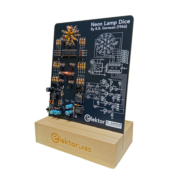
Een retro-rol met een neonziel
Dobbelstenen met leds zijn gebruikelijk, maar hun licht is koud. Dat geldt niet voor deze elektronische neon-dobbelsteen, die zijn waarde toont met de warme gloed van neonlampen. Hij is perfect om te spelen op koude, donkere winteravonden. De ogen van de dobbelsteen zijn neonlampen en de random number generator heeft zes neonlampen om aan te geven dat hij werkt.
Hoewel de dobbelsteen een ingebouwde 100 V-voeding heeft, is hij volkomen veilig. Zoals bij alle Elektor Classic-producten is ook bij de dobbelsteen het schema op de voorkant afgedrukt, terwijl een uitleg over de werking van de schakeling op de achterkant te vinden is.
De neonlamp-dobbelsteen wordt geleverd als een bouwpakket met eenvoudig te solderen doorlopende onderdelen. De voeding is een 9 V-batterij (niet meegeleverd).
Kenmerken
Warme vintage gloed
Elektor Heritage Circuit Symbolen
Getest en getest door Elektor Labs
Educatief en geeky project
Alleen doorlopende onderdelen
Inbegrepen
Printplaat
Alle componenten
Houten standaard
Vereist
9 V batterij
Stuklijst
Weerstanden (THT, 150 V, 0.25 W)
R1, R2, R3, R4, R5, R6, R14 = 1 MΩ
R7, R8, R9, R10, R11, R12 = 18 kΩ
R13, R15, R16, R17, R18, R21, R23, R24, R25, R26, R28, R30, R33 = 100 kΩ
R32, R34 = 1.2 kΩ
R19, R20, R22, R27, R29 = 4.7 kΩ
R31 = 1 Ω
Condensatoren
C1, C2, C3, C4, C5, C6 = 470 nF, 50 V, 5 mm pitch
C7, C9, C11, C12 = 1 µF, 16 V, 2 mm pitch
C8 = 470 pF, 50 V, 5 mm pitch
C10 = 1 µF, 250 V, 2.5 mm pitch
Spoelen
L1 = 470 µH
Halfgeleiders
D1, D2, D3, D4, D5, D6, D7 = 1N4148
D8 = STPS1150
IC1 = NE555
IC2 = 74HC374
IC3 = MC34063
IC4 = 78L05
T1, T2, T3, T4, T5 = MPSA42
T6 = STQ2LN60K3-AP
Diversen
K1 = PP3 9 V batterijhouder
NE1, NE2, NE3, NE4, NE5, NE6, NE7, NE8, NE9, NE10, NE11, NE12, NE13 = neonlicht
S2 = Miniatuurschuifschakelaar
S1 = Drukknop (12 x 12 mm)
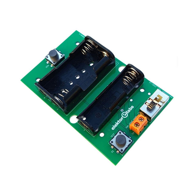
De Elektor Milliohmmeter Adapter gebruikt de precisie van een multimeter om zeer lage weerstandswaarden te meten. Het is een adapter die een weerstand omzet in een spanning die kan worden gemeten met een standaard multimeter.
De Elektor Milliohmmeter Adapter kan weerstanden meten onder 1 mΩ met behulp van een 4-draads (Kelvin) methode. Het is handig voor het lokaliseren van kortsluitingen op printplaten (PCB).
De adapter heeft drie meetbereiken – 1 mΩ, 10 mΩ en 100 mΩ – selecteerbaar via een schuifschakelaar. Het bevat ook ingebouwde kalibratieweerstanden. De Elektor Milliohmmeter Adapter wordt gevoed door drie 1,5 V AA batterijen (niet meegeleverd).
Specificaties
Meetbereiken
1 mΩ, 10 mΩ, 100 mΩ, 0,1%
Voeding
3x 1,5 V AA-batterijen (niet inbegrepen)
Afmetingen
103 x 66 x 18 mm (compatibel met Hammond 1593N-type behuizing, niet inbegrepen)
Speciale functie
Geïntegreerde kalibratieweerstanden
Downloads
Documentation
Resonances From Aether Days
A Pictorial and Technical Analysis from WWII to the Internet Age
From the birth of radio to the late 1980s, much of real life unfolded through shortwave communication. World War II demonstrated—beyond a shadow of a doubt—that effective communications equipment was a vital prerequisite for military success. In the postwar years, shortwave became the backbone on which many of the world's most critical services depended every day.
All the radio equipment—through whose cathodes, grids, plates, and transistors so much of human history has flowed—is an exceptional subject of study and enjoyment for those of us who are passionate about vintage electronics. In this book, which begins in the aftermath of World War II, you’ll find a rich collection of information: descriptions, tips, technical notes, photos, and schematics that will be valuable for anyone interested in restoring—or simply learning about—these extraordinary witnesses to one of the most remarkable eras in technological history.
My hope is that these pages will help preserve this vast treasure of knowledge, innovation, and history—a heritage that far transcends the purely technical.
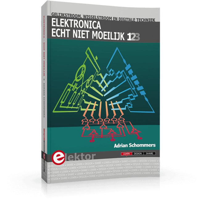
Elektronica moeilijk? De titel van dit boek geeft het antwoord!
In deze 3-in-1-band wordt de elektronica vanuit de praktijk benaderd. Dat wil zeggen veel praktijk in de vorm van experimenten en een minimum aan theorie. Zo raakt u stap voor stap vertrouwd met de behandelde onderwerpen. Daarbij ontstaan gaandeweg ook een flink aantal praktisch bruikbare schakelingen. Het gaat bij de elektronicahobby tenslotte om het bouwen of uitdenken van allerlei praktische of leuke schakelingen.
Aan het eind van elk deel is een aanhangsel opgenomen met aanvullende informatie en de gegevens van een groot aantal elektronische componenten, zodat na dit boek ook eigen ideeën en experimenten kunnen worden aangepakt.
In deze 3-in-1-band zijn de eerste drie delen uit de serie “Elektronica echt niet moeilijk” samengevoegd:
Deel 1: experimenten met gelijkstroom
Deel 2: experimenten met wisselstroom
Deel 3: experimenten met digitale techniek