De M12-mountlens (12 MP, 8 mm) is ideaal voor gebruik met de Raspberry Pi HQ Cameramodule en levert scherpe, gedetailleerde beelden voor uiteenlopende toepassingen.
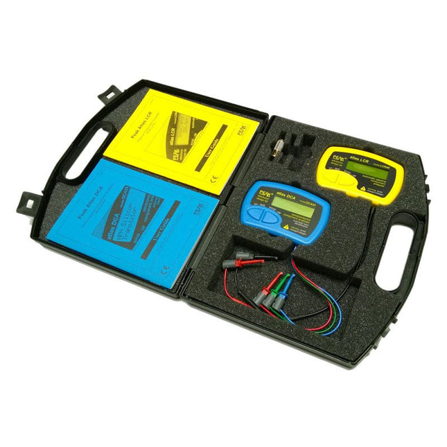
A fantastic dual instrument pack featuring the Atlas DCA Semiconductor Analyser and the Atlas LCR Passive Component Analyser. Housed in a robust padded case, complete with spare battery, user guide and space for accessories.
The LCR40 (for Inductors, Capacitors and Resistors) is ideal for the hobbyist and professional alike. The DCA55 (for most semiconductors) provides fast component identification, pinout identification and wide component support.
LCR40
Handheld LCR analyser providing measurements for inductance, capacitance and resistance. The component type is automatically detected for you, just connect and press 'test'. The test frequency is automatically selected to provide the best measurement resolution. Test frequencies include DC, 1kHz, 15kHz and 200kHz. Inductance from 1uH to 10uH, minimum resolution of 1uH, typical accuracy of ±1.5% between 100uH and 100mH. Capacitance from 1pF to 10,000uF, minimum resolution of 1pF typical accuracy of ±1.5% between 200pF and 500nF. Resistance from 1R to 2MR, typical accuracy of ±1%. Test frequency is displayed with the measurement. Inductor DC resistance also displayed when testing inductors. Supplied with removable gold plated hook probes, battery and user guide. Compatible with standard 2mm test connectors. Not designed for in-circuit use.
Automatic component type detection: Inductor, Capacitor or Resistor
Automatic test frequency selection: DC, 1kHz, 15kHz and 200kHz
Inductance from 1uH to 10H
Capacitance from 1pF to 10,000uF
Resistance from 1Ohm to 2MOhm
Inductance measurement also shows DC winding resistance
Test frequency displayed for all measurements
Typical accuracy of 1.5% for inductors and capacitors (see spec table for details)
Typical accuracy of 1% for resistors
Test lead complete with gold plated 2mm plugs and sockets
Supplied with removable gold plated hook probes
DCA55
Connect any way round to automatically identify and measure a wide range of semiconductor devices. The DCA55 will automatically identify the type of the part, pinout and many component parameters. Components supported include bipolar NPN/PNP transistors, darlingtons, diode-protected transistors, transistors with built-in resistors, enhancement mode MOSFETs, depletion mode MOSFETs, diodes, diode networks, LEDs, 2 and 3 lead bicolour LEDs, JFETs and many more. Further measurements are displayed including transistor gain, leakage current, pn voltage drops, LED voltages, MOSFET threshold voltages and much more. Even if you don't know anything about the part, just connect it in any configuration and the DCA55 will identify the type of part for you and also identify all the leads. Supplied with universal gold plated hook probes, battery and illustrated user guide. Not designed for in-circuit testing.
Automatic pinout detection and identification, connect any way round
Automatic part type identification
Supports semiconductors including transistors, MOSFETs, diodes, LEDs, JFETs and much more
Detection of special component features such as transistors with diodes or transistors with built-in resistors
Transistor gain measurement
Transistor leakage measurement
MOSFET gate threshold measurement
Semiconductor voltage drop measurement
Supplied with gold plated red/green/blue universal hook probes
Included
LCR40
DCA55
Extra GP23 Battery
Dual Carry Case
Add colors to your projects with this collection of red, green, yellow, blue and white LEDs. They come with various current limiting resistors in order to protect the parts and control the brightness.Included
10 mm LEDs
1x red
1x green
1x yellow
1x blue
1x white
5 mm LEDs
5x red
5x green
5x yellow
5x blue
5x white
3 mm LEDs
5x red
5x green
5x yellow
5x blue
5x white
25x 330 Ω resistors
10x 1 kΩ resistors
10x 10 kΩ resistors
10x 100 kΩ resistors
10x 1 MΩ resistors
LoRaWAN is nuttig, maar soms is het onnodig, moeilijk of duur om een LoRaWAN-netwerk te implementeren, vooral als je cloudintegratie overweegt. Voor het monitoren van bodemvocht in uw achtertuin of het volgen van de omstandigheden in de kas van uw boerderij is bijvoorbeeld mogelijk geen volledige LoRaWAN-installatie vereist.
Deze LoRa-ontvanger is ontworpen om te werken met Makerfabs SenseLora-modules. Het ontvangt LoRa-signalen en stuurt deze door naar een computer, zodat de gegevens op de computer kunnen worden weergegeven, geregistreerd en geanalyseerd.
Downloads
Manual
Software
LILYGO T-Display RP2040 Raspberry Pi Module 1.14-inch LCD Development Board This board is based on a Raspberry Pi Pico RP2040 with Dual Cortex-M0+ and 4 MB Flash memory. It is equipped with a 1.14-inch full color IPS display. The ST7789V display has a resolution of 135 x 240 pixels and is connected via the SPI interface. Specifications MCU RP2040 Dual ARM Cortex M0+ Flash 4 MB Bus interfaces 2x UART, 2x SPI, 2x I²C, 6x PWM Programming language C/C++, MicroPython Support machine learning library TensorFlow Lite Onboard functions Buttons: IO06+IO07, battery power detection TFT Display 1.14-inch ST7789V IPS LCD Resolution 135 x 240, full color Interface 4-Wire SPI interface Operating temperature -20°C ~ +70°C Working power supply 3.3 V Connector JST-GH 1.25 mm 2-pin Included LILYGO T-Display RP2040 Unsoldered headers JST cable Downloads Pinout GitHub
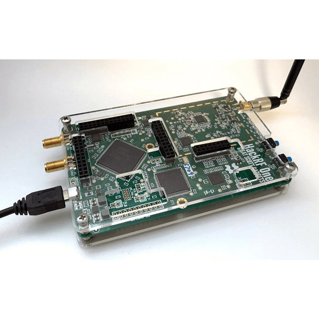
Deze doorzichtige acryl behuizing is de officiële behuizing voor het HackRF One-board. Hij kan de standaard zwarte plastic behuizing van de HackRF One vervangen.
Montage-instructies
Gebruik een plectrum of spudger om de HackRF One printplaat uit de zwarte plastic behuizing te halen.
Steek een lange schroef in elke hoek van het onderste acrylpaneel. Zet elke lange schroef vast met een kort afstandsstuk (5 mm) aan de tegenoverliggende kant van het paneel.
Plaats de HackRF One printplaat (naar boven gericht) bovenop het onderpaneel en steek de uiteinden van de lange schroeven door de bevestigingsgaten in de hoeken van de print.
Zet de printplaat vast met een lang afstandsstuk (6 mm) in elke hoek.
Plaats het bovenste acrylpaneel op de printplaat en lijn de uitsparingen uit met de extension headers op de print.
Zet elke hoek vast met een korte schroef.
Opmerking: Niet te strak aandraaien! Na elke stap alleen met de hand aandraaien.
STmicroelectronics’ wireless IoT & wearable sensor development kit
‘SensorTile.box’ is a portable multi-sensor circuit board housed in a plastic box and developed by STMicroelectronics. It is equipped with a high-performance 32-bit ARM Cortex-M4 processor with DSP and FPU, and various sensor modules, such as accelerometer, gyroscope, temperature sensor, humidity sensor, atmospheric pressure sensor, microphone, and so on. SensorTile.box is ready to use with wireless IoT and Bluetooth connectivity that can easily be used with an iOS or Android compatible smartphone, regardless of the level of expertise of the users. SensorTile.box is shipped with a long-life battery and all the user has to do is connect the battery to the circuit to start using the box.
The SensorTile.box can be operated in three modes: Basic mode, Expert mode, and Pro mode. Basic mode is the easiest way of using the box since it is pre-loaded with demo apps and all the user has to do is choose the required apps and display or plot the measured data on a smartphone using an app called STE BLE Sensor. In Expert mode users can develop simple apps using a graphical wizard provided with the STE BLE Sensor. Pro mode is the most complex mode allowing users to develop programs and upload them to the SensorTile.box.
This book is an introduction to the SensorTile.box and includes the following:
Brief specifications of the SensorTile.box; description of how to install the STE BLE Sensor app on an iOS or Android compatible smartphone required to communicate with the box.
Operation of the SensorTile.box in Basic mode is described in detail by going through all of the pre-loaded demo apps, explaining how to run these apps through a smartphone.
An introduction to the Expert mode with many example apps developed and explained in detail enabling users to develop their own apps in this mode. Again, the STE BLE Sensor app is used on the smartphone to communicate with the SensorTile.box and to run the developed apps.
The book then describes in detail how to upload the sensor data to the cloud. This is an important topic since it allows the sensor measurements to be accessed from anywhere with an Internet connection, at any time.
Finally, Pro mode is described in detail where more experienced people can use the SensorTile.box to develop, debug, and test their own apps using the STM32 open development environment (STM32 ODE). The Chapter explains how to upload the developed firmware to the SensorTile.box using several methods. Additionally, the installation and use of the Unicleo-GUI package is described with reference to the SensorTile.box. This PC software package enables all of the SensorTile.box sensor measurements to be displayed or plotted in real time on the PC.
Dit 10,1-inch HDMI-aanraakscherm heeft een high-definition resolutie van 1280x800 en ondersteunt een kijkhoek van 178°, wat een uitstekende visuele ervaring oplevert. Het ondersteunt Raspberry Pi, Windows, Linux, Ubuntu en andere systemen, en is ook compatibel met Raspberry Pi 3/3B+/4B/5, Jetson Nano, Beaglebone, Banana Pi en andere reguliere ontwikkelborden. Je kunt de gewenste helderheid eenvoudig aanpassen door de achtergrondverlichtingsknop aan te passen.
Dit capacitieve touchscreen van de Raspberry Pi ondersteunt 5-punts aanraking, heeft een hoge responssnelheid en high-definition communicatie ondersteunt plug-and-play. Het wordt geleverd met een standaard voor eenvoudige plaatsing op het bureaublad, en met montagegaten aan de achterkant kunt u om hem veilig aan een muur te bevestigen of te integreren met een kleine vormfactor SBC (single-board computer).
Om het scherm te beschermen en de visuele aantrekkingskracht te vergroten, wordt de monitor geleverd met een duurzame en stijlvolle acrylafdekking.
Of u nu een hoogwaardige monitor nodig heeft voor gaming, multimedia-entertainment of industriële toepassingen, onze 10-inch monitoren bieden superieure beelden, responsieve aanraakbediening, naadloze connectiviteit en veelzijdige montageopties.
Functies
IPS HD-resolutie van 1280 x 800 en een volledige kijkhoek van 178° bieden kristalheldere beelden en levendige kleuren voor een visuele ervaring van hoge kwaliteit
Ondersteuning van de achtergrondverlichting, deze kan worden aangepast met de knop
Ondersteunt capacitieve 5-puntsaanraking, maakt een soepele, nauwkeurige en snelle respons mogelijk
Gebruik HD-communicatie, plug-and-play en eenvoudig te gebruiken
Ondersteuning voor Windows, Linux, Ubuntu, Kodi, enz.
Compatibel met Raspberry Pi 3/3B+/4B/5, Jetson Nano, Beaglebone
Specificaties
Schermgrootte
10,1 inch
Schermtype
IPS-scherm
Resolutie
1280 x 800
Achtergrondverlichting aanpassen
Aanpassing sleutelschakelaar
Type aanraakscherm
Capacitief touchscreen
Touch-IC
SIS9200
Vermogen
Micro-USB (5 V)
Algeheel vermogen
5,2942 W (100% helderheid)
Video-invoerinterface
HDMI-compatibel (tot 1080p)
Actief gebied
216,6 x 135,4 mm
Afmetingen (L x B x H)
239,4 x 157,4 x 12,3 ±0,2 mm
Inbegrepen
1x 10,1 inch touchscreen
1x HD naar HD-kabel
2x USB-kabel
1x HD naar Mini HD-adapter
1x Schroevenpakket
2x Beugel
1x Schroevendraaier
1x Manual
Downloads
Manual
Wiki
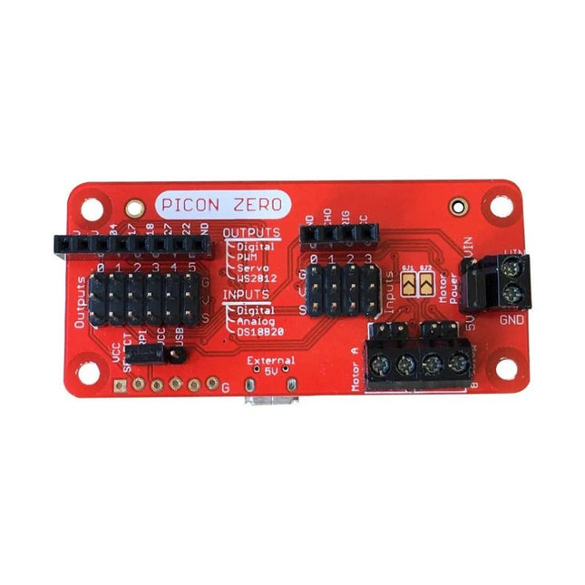
The Picon Zero is an add-on for the Raspberry Pi. It has the same size as a Raspberry Pi Zero, making it ideal to function as a pHat. Of course, it can be used on any other Raspberry Pi via a 40-pin GPIO connector.As well as two full H-Bridge motor drivers, the Picon Zero has several Input/Output pins giving you multiple configuration options. That allows you to easily add outputs or analog inputs to your Raspberry Pi without any complicated software or kernel-specific drivers. At the same time, it opens up 5 GPIO pins from the Raspberry Pi, and it provides the interface for an HC-SR04 ultrasonic distance sensor.The Picon Zero comes with all components, including the headers and screw terminals, fully soldered. Soldering isn't required. You can use it right out of the box.Features
pHat format PCB: 65 mm x 30 mm
Two full H-Bridge motor drivers. Drive up to 1.5 A continuously per channel, at 3 V - 11 V.
Each motor output has both a 2-pin male header and a 2-pin screw terminal.
The motors can be powered from the Picon Zero's 5 V or an external power source (3 V - 11 V).
The Picon Zero's 5 V can be selected to be from the Raspberry Pi's 5 V line, or a USB connector on the Picon Zero. That means that you can effectively have 2 USB battery banks: one to power the servos and motors on the Picon Zero and the other to power the Pi.
4 Inputs that can accept up to 5 V. These inputs can be configured as follows:
Digital inputs
Analog inputs
DS18B20
DHT11
6 Outputs that can drive 5 V and be configured as:
Digital Output
PWM Output
Servo
NeoPixel WS2812
All Inputs and Outputs use GVS 3-pin male headers.
4-pin female header that connects directly to an HC-SR04 ultrasonic distance sensor.
8-pin female header for Ground, 3.3 V, 5 V, and 5 GPIO signals allowing you to add their additional features.
Hardware ConfigurationPicon Zero has two jumpers for setting the hardware configuration. Ensure that you have placed them in the correct position.
JP1 – Board 5 V Selector. This jumper selects where to get the 5 V power from for the Picon Zero Outputs. The options are:
Jumper at the top between RPI and 5 V. The 5 V power for the board is taken from the Raspberry Pi pins on the GPIO connector. Because of the low power output devices and the 5 V motors, all devices can be powered with a single 5 V power input.
Jumper at the bottom between USB and 5 V. The 5 V power is taken from the microUSB connector on the Picon Zero. Useful for higher power output devices, since you can provide extra power through the micro-USB connector on the board
JP2 – Motor Power Selector. This jumper selects where the motors get the power. The two options here are the following:
Jumper at the top between MotorPower and Vin. The motors are driven via the 2-pin screw terminal. The voltage can be between 3 V and 11 V. Useful for motors that require a voltage different from 5 V, or that require more current than is available on either of the USB input connectors
Jumper at the bottom between 5 V and MotorPower. The motors are driven from the board's 5 V.
Raspberry Pi ConfigurationThe Picon Zero is an I²C device. Make sure your Raspberry Pi is set up correctly to use I²C and SMBus:
sudo apt-get install python-smbus python3-smbus python-dev python3-dev
sudo nano /boot/config.txt Add the following lines at the end of the file
dtparam=i2c1=on
dtparam=i2c_arm=on
Press Ctrl-X and use the default prompts to save
sudo reboot
Plugin the Picon Zero onto the Pi and run i2cdetect -y 1If everything goes well, you will see the Picon Zero showing up as address 22 as shown below:
Specifications
Datasheet
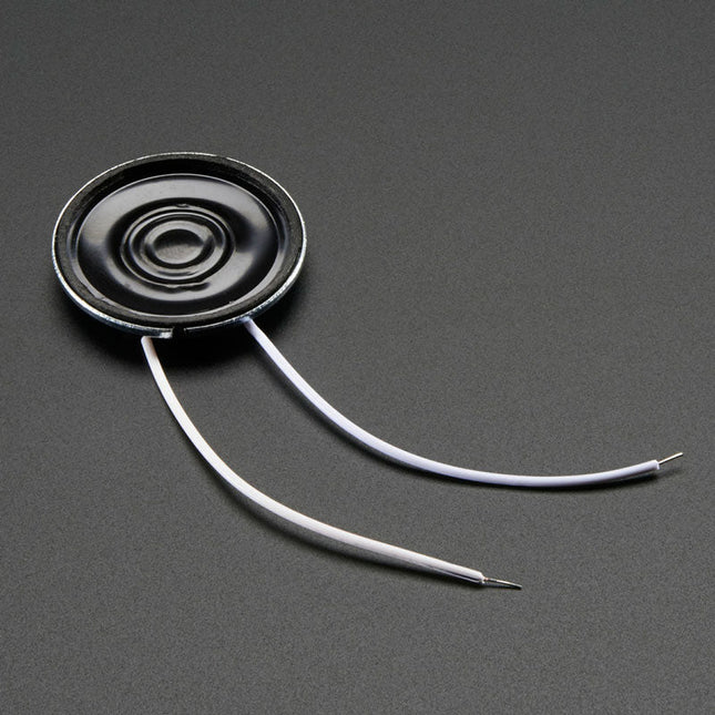
Resonance Frequency (FO): 680 ±20% Hz at 1 V
Rated Impedance: 8 ±20% Ω (at 1 KHz)
Frequency Range: ~600-10 KHz
Rated Input Power: 0.25 W
Max Input Power: 0.5 W
Temperature Range: -20ºC ~ 55ºC
Dimensions
Diameter: 28 mm / 1.1'
Height: 4.5 mm
Weight: 6 g
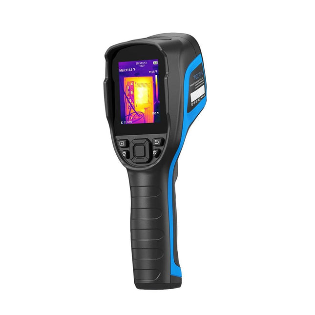
De TOPDON TC004 warmtebeeldcamera biedt een breed temperatuurbereik van -20°C tot 350°C met een batterijlevensduur van 12 uur. De camera heeft een infraroodcamera met een hoge resolutie van 256 x 192 pixels, wat zorgt voor heldere, gedetailleerde beelden.
Met een thermische gevoeligheid van 0,05°C kan hij subtiele temperatuurveranderingen detecteren. De camera detecteert automatisch het midden, warme en koude plekken, waardoor de visuele temperatuuranalyse wordt verbeterd. Het brede gezichtsveld van 56° legt meer vast in één enkele opname zonder dat er focusaanpassingen nodig zijn.
De TC004 biedt nauwkeurige metingen met een nauwkeurigheid van ±2°C, een NETD van minder dan 40 mK en een resolutie tot 0,1°C. Hij ondersteunt zowel standalone als PC modi, zodat gebruikers beelden kunnen uploaden en projecteren voor eenvoudige analyse. De ingebouwde LED-lamp maakt gebruik bij weinig licht mogelijk en de professionele software vereenvoudigt het delen van gegevens.
Kenmerken
Breed temperatuurbereik van −20°C tot 350°C
Realtime foto- en video-opname
5 kleurenpaletten voor meer mogelijkheden
Statief monteerbaar voor een stabiel zicht
Alarm voor hoge en lage temperatuur
Bewaak temperatuurveranderingen met golfvormgrafieken
Langdurige batterijduur van 12 uur
PC-beeldanalyse en directe projectie
Ingebouwd LED-licht
Specificaties
TC004
TC004 SE
TC004 Lite
Display
2,8" kleuren-TFT (320 x 240 pixels)
2,8" kleuren-TFT (320 x 240 pixels)
2,8" kleuren-TFT (320 x 240 pixels)
IR-lichtresolutie
256 x 192 pixels
256 x 192 pixels
160 x 120 pixels
Spectraal bereik
8~14 μm
8~14 μm
8~14 μm
FOV
52,5° x 39,5°
56° x 42°
40° x 30°
Opslag
2 GB RAM + 16 GB TF-kaart
32 GB (ingebouwd)
512 MB (ingebouwd)
Meetbereik
−20~350°C
−20~550°C
−20~550°C
Temperatuurresolutie
0,1°C
0,1°C
0,1°C
Meetmodi
Centrum/heetste punt/koudste punt
Centrum/heetste punt/koudste punt
Centrum/heetste punt/koudste punt
Meetnauwkeurigheid
±2°C of ±2%
±2°C of ±2%
±2°C of ±2%
Framerate
25 Hz
25 Hz
25 Hz
Brandpuntsafstand
3,2 mm (0,12")
3,2 mm (0,12")
2,6 mm (0,1")
NETD
<40 mK
<40 mK
<40 mK
Vergroting
1x/2x/4x (digitale zoom)
1x/2x/4x (digitale zoom)
1x/2x/4x (digitale zoom)
Statiefschroefgat
Ja
Ja
Ja
Alarm hoge/lage temperatuur
Ja
Ja
Ja
LED-licht
Ja
Ja
Nee
Video-opname
Ja
Ja
Nee
Automatische uitschakeling
5 min, 10 min, 20 min, UIT
5 min, 10 min, 20 min, UIT
5 min, 10 min, 20 min, UIT
Batterij
Ingebouwde batterij van 5000 mAh
Ingebouwde batterij van 5300 mAh
Ingebouwde batterij van 2900 mAh
Oplaadtijd
4 uur
4 uur
4 uur
Stand-bytijd
12 uur
16 uur (hoge helderheid)21 uur (lage helderheid)
15 uur
Besturingssysteem
Standalone gebruik/Windows-apparaten
Standalone gebruik/Windows-apparaten
Standalone gebruik
PC-gebaseerde analyse
Ondersteunt beeldanalyse met PC
Ja
Nee
Afmetingen
240 x 70 x 90 mm
240 x 70 x 90 mm
240 x 70 x 90 mm
Gewicht
520 g
520 g
520 g
Inbegrepen
1x TOPDON TC004 Warmtebeeldcamera
1x USB-voeding
4x Stekkers (EU, UK, US en AU)
1x USB-kabel
1x Opbergtas
1x Manual
Downloads
Datasheet
Manual
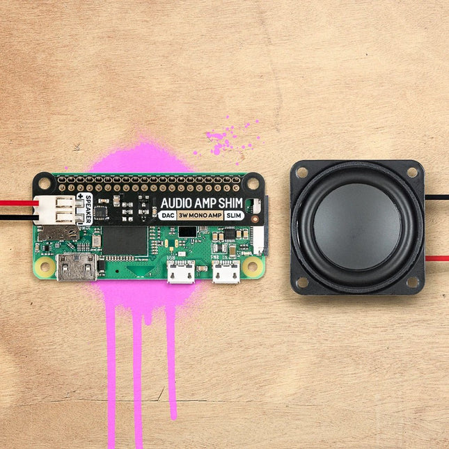
SHIM is een oude Yorkshire term die 'Shove Hardware In Middle' betekent - wij gebruiken het voor Raspberry Pi add-ons die zijn ontworpen om tussen uw Pi en een HAT of mini HAT te worden geklemd. Deze heeft een slimme friction fit header die gemakkelijk over je GPIO pinnen glijdt, niet gesoldeerd hoeft te worden*, en gemakkelijk te verwijderen is.De MAX98357A gecombineerde DAC/versterker-chip neemt digitale audio van hoge kwaliteit van uw Pi en versterkt deze, zodat deze kan worden gebruikt met een luidspreker zonder voeding. De push-fit connectors maken het eenvoudig om uw luidspreker aan te sluiten, of het nu een boekenplank of vloerstaande luidspreker is, de luidspreker in een oude radio, of een andere luidspreker die u misschien heeft liggen. Omdat Audio Amp SHIM geen extra ruimte toevoegt aan uw Pi, is het perfect om in te bouwen in een compacte behuizing - u kunt het gebruiken om een kleine MP3-speler te maken om lokale bestanden af te spelen of te streamen van diensten zoals Spotify, een vintage radio de mogelijkheid te geven om digitale radiostreams af te spelen of bliepgeluiden te integreren in uw eigen retro handheld. Het is ook een handige manier om audio-uitgang aan uw Pi Zero of Pi 400 toe te voegen!Let op: Raspberry Pi and speakers zijn niet inbegrepen bij dit board. Features
MAX98357A DAC / amplifier chip
Mono 3W audio out
Push-fit speaker terminals
SHIM-format board with friction-fit connectors
2x mounting holes (M2.5) for if you want to secure everything together with bolts
Fully-assembled
No soldering required (*unless you're using a Pi that comes without a header)
Compatible with all 40-pin header Raspberry Pi models
SoftwareDe eenvoudigste manier om alles in te stellen is gebruik te maken van Pimoroni's Pirate Audio software en installer die I2S audio configureert, alsook Mopidy installeert en onze aangepaste Pirate Audio plugins waarmee u Spotify kunt streamen en lokale bestanden kunt afspelen.Hier is hoe te beginnen:
Stel een SD-kaart in met de laatste versie van Raspberry Pi OS.
Maak verbinding met Wi-Fi of een bekabeld netwerk.
Open een terminal en type het volgende:git clone https://github.com/pimoroni/pirate-audiocd pirate-audio/mopidysudo ./install.sh
Reboot your Pi
Downloads
MAX98357A Datasheet
Pirate Audio software
Schematic
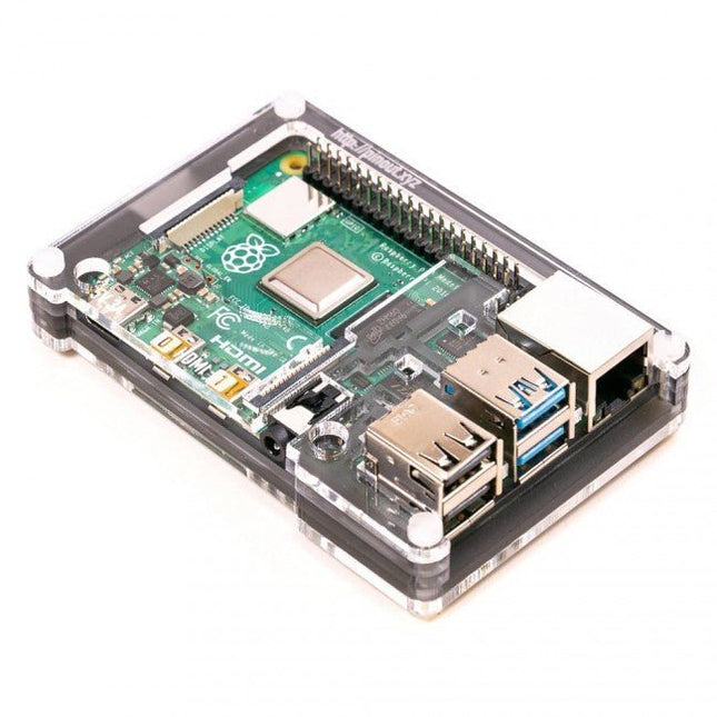
Features Compatible with Raspberry Pi 4 only
Cutout in lid for 40x30mm heatsink or Fan SHIM
Super-slimline profile Fully HAT-compatible Protects your beloved Pi Clear top and base leave Raspberry Pi 4 visible GPIO cut-out Handy laser-etched port labels Leaves all ports accessible Made from lightweight, high-quality, cast acrylic Great for hacking and tinkering! Made in Sheffield, UK Weighing just over 50 grams, the case is lightweight and ideal for mounting to any surface. No tools are required for assembly or disassembly. The dimensions are: 99 × 66 × 15 mm. In the video below you can see a quick assembly guide.
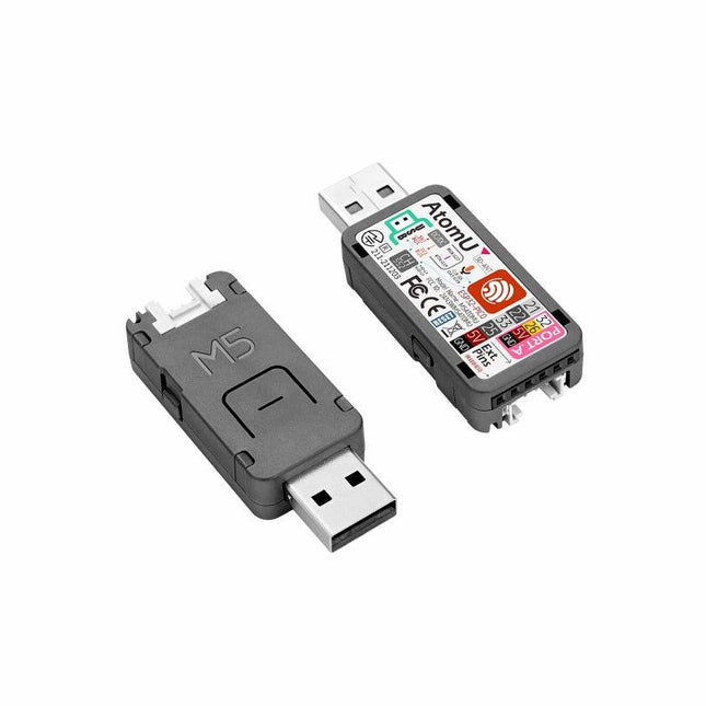
ATOM U is a compact low-power consumption speech recognition IoT development kit. It adopts an ESP32 chipset, equipped with 2 low-power Xtensa 32-bit LX6 microprocessors with the main frequency of up to 240 MHz. Built-in USB-A interface, IR emitter, programmable RGB LED. Plug-and-play, easy to upload and download programs. Integrated Wi-Fi and digital microphone SPM1423 (I2S) for the clear sound record. suitable for HMI, Speech-to-Text (STT). Low-code development ATOM U supports UIFlow graphical programming platform, scripting-free, cloud push; Fully compatible with Arduino, MicroPython, ESP32-IDF, and other mainstream development platforms, to quickly build various applications. High integration ATOM U contains a USB-A port for programming/power supply, IR emitter, programmable RGB LED x1, button x1; Finely tuned RF circuit, providing stable and reliable wireless communication. Strong expandability ATOM U is easy access to M5Stack's hardware and software system. Features ESP32-PICO-D4 (2.4GHz Wi-Fi dual mode) Integrated programmable RGB LED and button Compact design Built-in IR emitter Expandable pinout and GROVE port Development platform: UIFlow MicroPython Arduino Specifications ESP32-PICO-D4 240MHz dual core, 600 DMIPS, 520KB SRAM, 2.4G Wi-Fi Microphone SPM1423 Microphone sensitivity 94 dB SPL@1 KHz Typical value: -22 dBFS Microphone signal-to-noise ratio 94 dB SPL@1 KHz, A-weighted Typical value: 61.4 dB Standby working current 40.4 mA Support input sound frequency 100 Hz ~ 10 KHz Support PDM clock frequency 1.0 ~ 3.25 MHz Weight 8.4 g Product size 52 x 20 x 10 mm Downloads Documentation
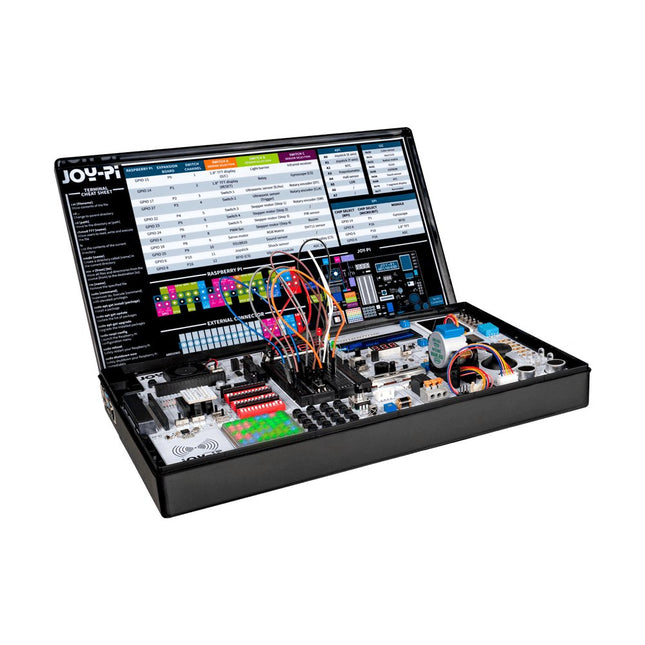
De Joy-Pi Advanced is een compact en krachtig instrument waarmee je snel en eenvoudig je projecten kunt realiseren. Of je nu veel of weinig ervaring hebt, met de Joy-Pi Advanced kun je je creativiteit de vrije loop laten. Dankzij de compatibiliteit met een groot aantal platformen, waaronder Raspberry Pi, Raspberry Pi Pico, Arduino Nano, BBC micro:bit en NodeMCU ESP32, kun je eenvoudig en snel toegang krijgen tot het platform van je voorkeur.
Daarnaast heeft de Joy-Pi Advanced meer dan 30 stations, lessen en modules, waardoor je een onbeperkt aantal manieren hebt om je projecten uit te voeren. Met het zelfontwikkelde leercentrum kun je niet alleen je vaardigheden verbeteren, maar ook nieuwe projecten maken. Het leercentrum biedt een schat aan informatie en tutorials die je stap voor stap door je projecten begeleiden.
Joy-Pi Advanced wordt in het bijzonder gekenmerkt door zijn intelligente schakeleenheden, die een uitgebreid gebruik van de beschikbare pinnen mogelijk maken. In totaal zijn er drie schakeleenheden geïntegreerd, elk voorzien van 12 individuele schakelaars die zorgen voor een nauwkeurige aansturing van de aangesloten sensoren en modules. Dit systeem lost het bekende probleem van het beperkte aantal pinnen op dat optreedt bij conventionele microcontrollers. Met de schakeleenheden kun je een groot aantal sensoren en modules parallel aansturen door ze afzonderlijk aan en uit te schakelen. Dit simuleert meervoudige pintoewijzing, waardoor je het volledige vermogen van je projecten kunt benutten zonder afbreuk te doen aan de functionaliteit.
Door onze innovatieve adapter boards en het micro:bit slot te combineren, bereiken we naadloze compatibiliteit met een breed scala aan microcontrollers zoals Raspberry Pi Pico, NodeMCU ESP32, micro:mit en Arduino Nano. De speciaal ontwikkelde adapterkaarten zijn zo ontworpen dat ze perfect passen bij de betreffende microcontroller. Door de microcontroller op het juiste adapterboard aan te sluiten en deze vervolgens in het micro:bit slot te steken, wordt de Joy-Pi Advanced snel en eenvoudig compatibel met de verschillende microcontrollers. Dit zorgt voor een naadloze integratie van het platform van je voorkeur en de mogelijkheid om de sterke punten van de verschillende microcontrollers te combineren in je projecten. Op deze manier kun je je volledig richten op je creatieve projecten zonder dat je je zorgen hoeft te maken over de compatibiliteit van verschillende microcontrollers. De Joy-Pi Advanced vereenvoudigt het ontwikkelproces en geeft je de mogelijkheid om je projecten flexibel en individueel te ontwerpen.
Kenmerken
Sterk geïntegreerd ontwikkelplatform & leercentrum
Snel, eenvoudig & draadloos combineren van verschillende sensoren & actuatoren
Installatieoptie voor Raspberry Pi 4
Compatibel met verschillende microcontrollers
Zelfontwikkeld, didactisch leerplatform voor Raspberry Pi & Windows
Specificaties
Compatibel met
Raspberry Pi 4, Arduino Nano, NodeMCU ESP32, BBC micro:bit, Raspberry Pi Pico
Geïnstalleerde sensoren, actuatoren & componenten
39
Leerplatform
Meer dan 40 items in de kennisdatabase, 10 projecten, 10 lessen, 14 visies
Displays
7-segment display, 16x2 display, 1,8' TFT-display, 0,96" OLED-display, 8x8 RGB-matrix
Sensoren
DS18B20, schoksensor, hallsensor, barometer, geluidssensor, gyroscoop, PIR-sensor, Lichtbarrière, NTC, Lichtsensor, 6x aanraaksensor, kleurensensor, ultrasone afstandssensor, DHT11 temperatuur- & vochtigheidssensor
Controle
Joystick, 5x schakelaars, potentiometer, draaiencoder, 4x4 knoppenmatrix, relais, PWM-ventilator
Motoren
Servo-interface, Stappenmotorinterface, Trilmotor
Meet- en conversiemodules
Analoog-digitaalomzetter, niveauomzetter, voltmeter, variabele spanningsbron
Andere onderdelen
RTC real-time klok, zoemer, EEPROM-geheugen, infrarood ontvanger, breadboard, RFID-lezer
Adapterkaarten
Adapter voor NodeMCU ESP32, Arduino Nano & Raspberry Pi Pico, Board connectors voor Raspberry Pi & externe boards
Elektronische onderdelen
Infrarood afstandsbediening, RFID-chip, RFID-kaart, 6x krokodillenklemmen, microSD-kaartlezer, servomotor, stappenmotor, 32 GB microSD-kaart
Onderdelen
40x weerstanden, 3x groene LED's, 3x gele LED's, 3x rode LED's, 1x transistor, 5x knoppen, 1x potentiometer, 2x condensatoren
Andere accessoires
Schroevenassortiment, schroevendraaier, accessoire-opbergtas, voeding & voedingskabel, servo bevestiging
Stroomvoorziening
Ingebouwde voeding: 36 W, 12 V, 3 A Behuizingsconnector: Kleine apparaat stekker C8
Spanningsuitgangen
12 V, 5 V, 3,3 V, variabele spanningsuitgang (2-11 V)
Databussen & signaaluitgangen
I²C, SPI, Analoog naar digitaal converter
Batterij (RTC)
CR2032
Afmetingen
327 x 200 x 52 mm
Vereist
Raspberry Pi 4 met minstens 2 GB RAM
Downloads
Joy-Pi website
Datasheet
Manual
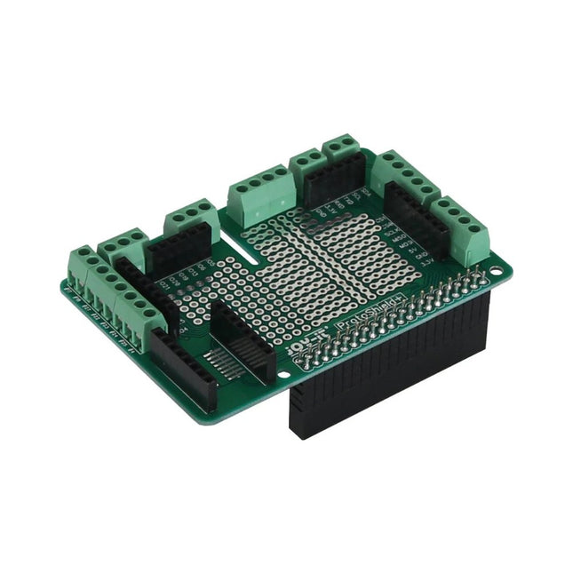
With our Proto+ prototype circuit board your own designs and projects can be implemented easily. The board is equipped with all popular connectors and also has a built-in breadboard for quick implementation of your ideas and developments.The built-in GPIO bar allows the expansion board to be easily plugged onto a Raspberry Pi and can be used immediately. The supplied screws and spacers allow the PCB to be connected directly to the Raspberry Pi. The screw terminals are already installed and facilitate the use and fast experimenting. MODEL Proto+ Prototyp-Board AVAILABLE CONNECTIONS GPIO (40-pole), SOIC16, Breadboard, 2x 3,3V, 2x 5V, UART, I2C, SPI NOTICE The outter screw terminals are connected to the GPIO connectors. COMPATIBLE TO Raspberry Pi B+, 2, 3 DIMENSIONS 55 x 85 mm WEIGHT 44 g ITEMS SHIPPED Proto+ Board, Screws, Spacers EAN 4250236814797 ARTICLE NO. RB-Proto+
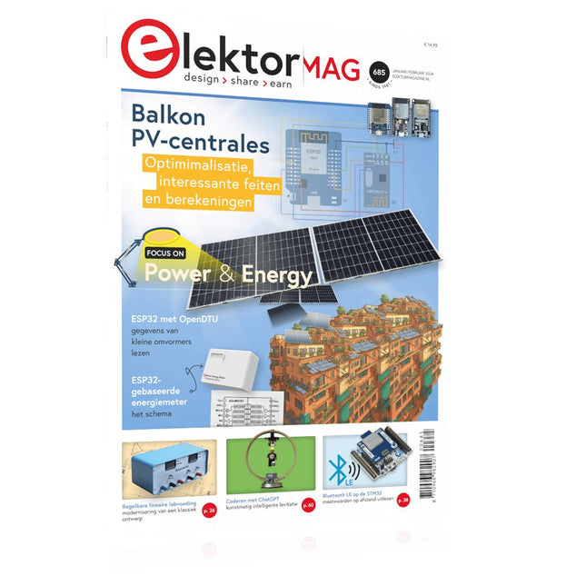
Elektor GREEN en GOLD leden kunnen deze uitgave hier downloaden.
Nog geen lid? Klik hier om een lidmaatschap af te sluiten.
Project-update: ESP32-gebaseerde energiemeterwe gaan verder met het prototype
Optimalisatie van balkon PV-centralesoverwegingen, interessante feiten en berekeningen
ESP32 met OpenDTU voor balkoncentralesgegevens van kleine omvormers via MCU’s uitlezen
Regelbare lineaire labvoeding0...50 V / 0...2 A + dubbele symmetrische voeding
Energieopslag – vandaag en morgeneen vraaggesprek met Simon Engelke
2024: een AI-odysseehet houdt nog lang niet op
Bluetooth LE op de STM32meetwaarden op afstand uitlezen
Mensvriendelijk slim keuken-voorraadsysteem
MAUI: programmeren voor PC, tablet en smartphonehet nieuwe framework in theorie en praktijk
ChatMagLevkunstmatig intelligente levitatie
Eenvoudige PV-regelaarbouw je eerste, volledig functionele PV-energiebeheersysteem
Koude-kathode-buizenvreemde onderdelen
Uit het leven gegrepennostalgie
Alle begin......bekijkt de FET
CAN-bus voor de Arduino UNO R4: een tutorialtwee UNO R4’s nemen de bus!
Elektor infographicvoeding en energie
Vergelijking van vermogensdichtheid en vermogensefficiëntie
Aluminium elektrolytische condensatorenstoringspotentieel in audiotechnologie
USB testen en metenmet de Fnirsi FNB58
De Pixel Pump pick&place-tooleenvoudiger handmatige assemblage van SMT-printen
Oost West Lab Bestnog niet zo lang geleden, in een land heel ver van hier...
“In de wereld van ethiek in elektronica kunnen zelfs kleine stappen een aanzienlijke invloed hebben.”
Ethiek in elektronicade OECD Guidelines en het Lieferkettensorgfaltspflichtengesetz
Chadèche: slimme NiMH-(ont)laderlezersproject in het kort
Project 2.0correcties, updates en brieven van lezers
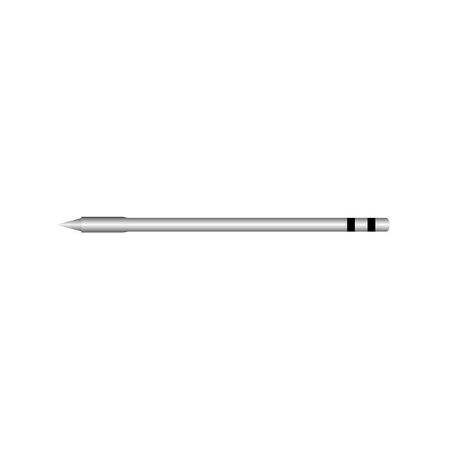
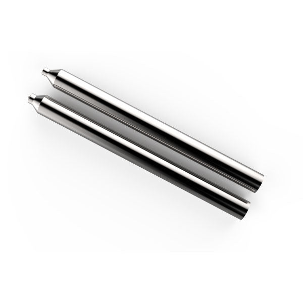
Use the right tool for the right job. These steel stakes are used to press the rivets on the PCB after holes have been drilled. They have been designed for optimum performance on the ink and ensure an electrical connection between the top and bottom layers of your PCB. Learn how to use them here.
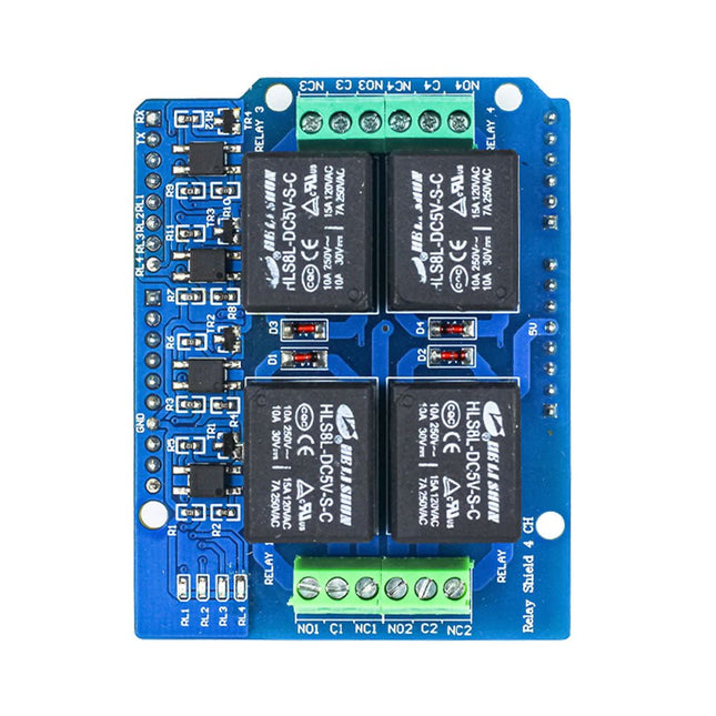
Enhance your Arduino projects with the Ardi Relay Shield, a versatile 4-channel optoisolated relay board. Designed to handle AC (250 V, 7 AMP) and DC (30 V, 10 AMP) power, this shield empowers you to easily control a wide range of electrical devices.
Equipped with four LED relay indicators, the Ardi Relay Shield provides visual feedback on the status of each relay, ensuring you stay informed and in control of your circuit. The shield also features four 3-pin screw terminals (NC, NO, COM) for convenient and secure connections.
Designed in the Arduino form factor, this shield seamlessly integrates with your Arduino Uno, allowing you to expand its capabilities and create interactive projects. Whether you're automating home appliances, building intelligent systems, or working on industrial applications, the Ardi Relay Shield is the reliable choice for robust and efficient relay control.
Features
4-channel optoisolated relay so better electrical isolation between High and Low side voltage.
4x Relay shield compatible with both 3.3 V and 5 V MCU
Onboard 4 Status LED to indicate each relay ON/OFF State
High-quality relays
Provides NO/NC interfaces with Screw terminals.
Mounts directly onto ArdiPi, Ardi32 or other Arduino compatible boards
Specifications
Max Switching Voltage: 250 V AC/30 V DC
Max Switching Current: 7 A/10 A
Max Switching Power: 2770 VA/240 W
Frequency: 1 Hz
Initial Contact Resistance: 50 m? max at 6 V DC/1 A
Operate Time: 10ms max
Release Time: 5ms max
Life Expectancy Electrical: 100,000 operations (rated load)
Life Expectancy Mechanical: 10,000,000 operations (no load)
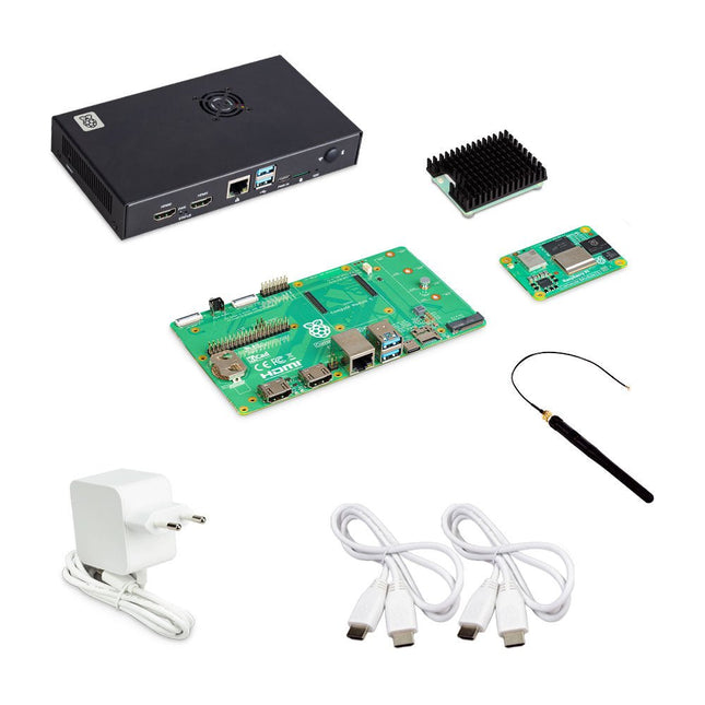
De Raspberry Pi Compute Module 5 Development Kit biedt een ideaal platform voor het prototypen van ingebedde oplossingen. Deze alles-in-één kit bevat de Compute Module 5, het Compute Module 5 IO Board en alle benodigde accessoires om uw productontwerp te starten.
Compute Module 5 (CM5104032)
2,4-GHz quad-core 64-bit Arm Cortex-A76 CPU
VideoCore VII GPU, ondersteunt OpenGL ES 3.1 en Vulkan 1.3
4 GB LPDDR4X-4267 SDRAM
32 GB MLC eMMC-geheugen
1x Dual 4Kp60 HDMI-schermuitgang
1x 4Kp60 HEVC-decoder
1x Dual-band 802.11ac wifi en Bluetooth 5.0
2x USB 3.0-interfaces, die gelijktijdige 5 Gbps-werking ondersteunen
1x Gigabit Ethernet, met IEEE 1588-ondersteuning
2x MIPI-camera/display-zendontvangers met 4 rijstroken
1x PCIe 2.0-interface voor snelle randapparatuur
30 GPIO's, die werking op 1,8 V of 3,3 V ondersteunen
Randapparatuur: UART, SPI, I²C, I²S, SDIO en PWM
Compute Module 5 IO Board
1x Standaard 40-pins GPIO
2x HDMI 2.0 op volledige grootte
2x 4-baans MIPI DSI/CSI-2 FPC (22-pins kabel met een steek van 0,5 mm)
2x USB 3.0
1x Gigabit Ethernet-aansluiting met PoE+ ondersteuning (vereist een aparte Raspberry Pi PoE+ HAT+)
1x M.2 M-key PCIe-socket (voor 2230, 2242, 2260 en 2280 modules)
1x microSD-kaartsleuf (voor gebruik met Lite-modules)
1x RTC-batterijaansluiting
1x 4-pins ventilatorconnector
Compute Module 5 IO-behuizing
De metalen behuizing transformeert het IO Board in een volledig gesloten computer van industriële kwaliteit. De IO-behuizing is speciaal ontworpen voor de Raspberry Pi Compute Module 5 en beschikt over een ingebouwde ventilator die wordt aangesloten op de 4-pins ventilatorconnector van het IO Board, waardoor verbeterde thermische prestaties worden gegarandeerd.
Inbegrepen
1x Raspberry Pi Compute Module 5 (Wireless, 4 GB RAM, 32 GB eMMC)
1x Raspberry Pi Compute Module 5 IO Board (voorgemonteerd geleverd in de IO-behuizing)
1x Raspberry Pi Compute Module 5 IO-behuizing
1x Raspberry Pi Compute Module 5 koeler
1x Raspberry Pi antennekit
1x Raspberry Pi 27 W USB-C PD voeding (EU)
2x Raspberry Pi HDMI naar HDMI-kabels
1x Raspberry Pi USB-A naar USB-C kabel
Downloads
Datasheet (Compute Module 5)
Datasheet (IO Board)
Datasheet (IO Case)
Datasheet (Cooler)
Datasheet (Antenna Kit)
This board is an all-digital conversion of Raspberry Pi's VGA reference design, great for if you want to start hacking on video and/or audio output from a Raspberry Pi Pico and piping it straight into a modern monitor.Features
HDMI connector
PCM5100A DAC for line out audio over I²S (datasheet)
SD card slot
Reset button
Socket headers to install your Raspberry Pi Pico
Three user-controllable switches
Rubber feet
Compatible with Raspberry Pi Pico
No soldering required (as long as your Pico has header pins attached)
Programmable with C/C++
Note: Raspberry Pi Pico is not included. Your Pico will need to have pin headers soldered to it (with the pins pointing downwards) to attach to our add-on boards.Downloads
Schematic
GitHub
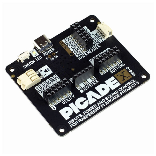
Turn your Raspberry Pi into a retro games console! Picade X HAT includes joystick and button inputs, a 3 W I²S DAC/amplifier, and soft power switch. This HAT has all the same great features as the original Picade HAT but now has no-fuss female Dupont connectors to hook up your joystick and buttons. Simply pop Picade X HAT onto your Pi, plug a USB-C power supply into the connector on the HAT (it back-powers your Pi through the GPIO, so no need for a separate power supply), wire up your controls, and install the driver! It's ideal for your own DIY arcade cabinet builds, or for interfaces that need big, colourful buttons and sound. Features I²S audio DAC with 3 W amplifier (mono) and push-fit terminals Safe power on/off system with tactile power button and LED USB-C connector for power (back-powers your Pi) 4-way digital joystick inputs 6x player button inputs 4x utility button inputs 1x soft power switch input 1x power LED output Plasma button connector Breakout pins for power, I²C, and 2 additional buttons Picade X HAT pinout Compatible with all 40-pin Raspberry Pi models The I²S DAC blends both channels of digital audio from the Raspberry Pi into a single mono output. This is then passed through a 3 W amplifier to power a connected speaker. The board also features a soft power switch that allows you turn your Pi on and off safely without risk of SD card corruption. Tap the connected button to start up, and press and hold it for 3 seconds to fully shutdown and disconnect power. Software/Installation Open a terminal and type curl https://get.pimoroni.com/picadehat | bash to run the installer. You'll need to reboot once the installation is complete, if it doesn't prompt you to do so. The software does not support Raspbian Wheezy Notes With USB-C power connected through Picade X HAT you'll need either to tap the connected power button or the button marked 'switch' on the HAT to power on your Pi.
The M5Stack Core Ink Development Kit is a new E-Ink display that uses an ESP32-Pico-D4 to take advantage of the benefits of the E-Ink technology.
E-Ink displays are easier on the eyes, have extremely low power consumption and can retain an image even after they have run out of power.
Features
ESP32 Standard wireless functions WiFi, Bluetooth
Internal 4M Flash
Low Power Display
180-degree viewing angle
Expansion ports
Built-in Magnet
Internal Battery
Multi-function button
Status LED
Buzzer
Deep Sleep functionality
Applications
IoT Terminal
E-Book
Industrial Control Panel
Electronic Tag
Included
1x CoreInk
1x LiPo 390 mAh
1x Type-C USB(20cm)
Please note: avoid long-time high-frequency refresh when using it. The recommended refresh interval is (15s/time). Do not expose to ultraviolet rays for a long time, otherwise, it may cause irreversible damage to the ink screen.