Standard 2x16 LCD (see Elektor Labs Preferred Parts - ELPP) with the following specifications: 2 rows, 16 characters wide 5 x 7 dots font and cursor Yellow-green LCD with yellow-green LED backlight HD44780 equivalent LCD controller High contrast Readable in sunlight 16 pin Connection port is 2.54 mm (0.1') pitch, single row for easy breadboarding and wiring pinning (left-to-right): 1-14,A,K Single LED backlight included; Easily dimmed with a resistor or via PWM; Uses much less power than electroluminescent backlights Can be fully controlled with only 6 digital lines(in 4-bit bus mode) 5V DC operating voltage Module dimension: 80 x 36 x 10 mm Viewing area size: 64.5x 15 mm
CrowBot BOLT is an ESP32-controlled, intelligent, simple and easy-to-use open source robot car. It is compatible with the Arduino and MicroPython environments, with graphical programming via Letscode. 16 learning courses with interesting experiments are available.
Kenmerken
16 lessons in three languages (Letscode, Arduino, Micropython), fast learning and fun experiments
Compatible with Arduino, MicroPython development environment, using Letscode graphical programming, easy to use
Strong scalability, with a variety of interfaces, can be expanded and used with Crowtail modules
A variety of remote control modes, you can use the infrared remote control and joystick to control the car
Specificaties
Processor
ESP32-Wrover-B (8 MB)
Programming
Letscode, Arduino, Micropython
Control method
Bluetooth Remote Control/Infrared Remote Control
Input
Button, Light sensor, Infrared Receiving Module, Ultrasonic Sensor, Line Tracking Sensor
Output
Buzzer, Programmable RGB Light, Motor
Wifi & Bluetooth
Yes
Light sensor
Can realize the function of chasing light or avoiding light
Ultrasonic Sensor
When an obstacle is detected, the driving route of the car can be corrected to avoid the obstacle
Line Tracking Sensor
Can make the car move along the dark/black lines, intelligently judge and correct the driving path
Buzzer
Can make the car sound/whistle, bringing a more direct sensory experience
Programmable RGB Light
Through programming, it can show colorful lights in different scenes
Infrared receiver
Receive infrared remote control signals to realize remote control
Interfaces
1x USB-C, 1x I²C, 1x A/D
Motor type
GA12-N20 Micro DC Gear Motor
Operating temperature
-10?~+55?
Power supply
4x 1.5 V batteries (not included)
Battery life
1.5 hours
Dimensions
128 x 92 x 64 mm
Weight
900 g
Inbegrepen
1x Chassis
1x Ultrasonic Sensor
1x Battery Holder
2x Wheels
4x M3x8 mm Screws
2x M3x5 mm Copper Column
2x Side Acrylic Plates
1x Front Acrylic Plates
1x Screwdriver
2x 4 Pin Crowtail Cable
1x USB-C Cable
1x Infrared remote control
1x Instructions & Line Track Map
1x Joystick
Downloads
Wiki
CrowBot-BOLT_Assembly-Instruction
Joystick-for-CrowBot-BOLT_Assembly-Instruction
CrowBot_BOLT_Beginner’s_Guide
Designing Documents of CrowBot
Designing Documents of Joystick
Lesson Code
3D Model
Factory Source Code
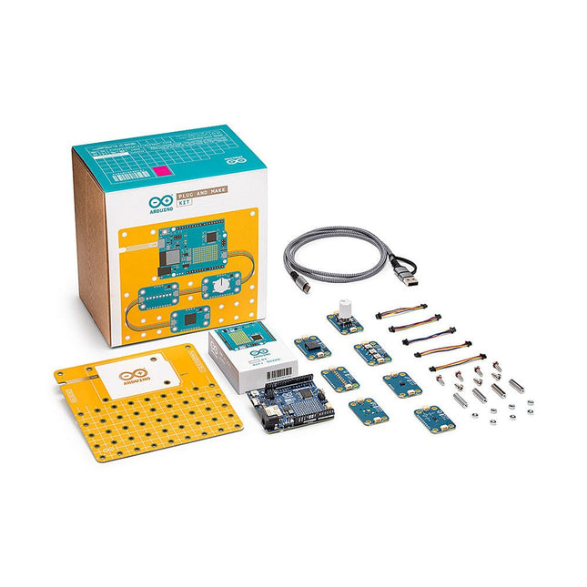
Bouw je eerste IoT-apparaten met deze kit door hardware en software naadloos te integreren zonder in complexe theorie te duiken.
Plug and Make Kit is de gemakkelijkste manier om aan de slag te gaan met Arduino. Het bevat alles wat je nodig hebt voor je allereerste zeven projecten – en nog veel meer die onze community deelt en die je zelf kunt uitvinden!
Weerrapport: Nooit meer in de regen terechtkomen, met een visuele herinnering om een paraplu mee te nemen als dat nodig is
Zandloper: Wie heeft er een eierwekker nodig? Pas je eigen digitale zandloper aan
Eco Watch: zorg ervoor dat uw planten gedijen bij de perfecte temperatuur en vochtigheid
Gamecontroller: Ga naar een hoger niveau met je eigen HID-gamepad (Human Interface Device)
Sonic Synth: Kom een stap dichter bij het worden van een rockster, DJ of geluidstechnicus!
Smart Lights: Creëer de sfeer met je eigen slimme lamp
Touchless lamp: Bedien lampen met een eenvoudig gebaar
Elk idee is inspiratie voor een leuke activiteit die je niet alleen de basisbeginselen van doe-het-zelf-elektronica leert, maar je ook een groot gevoel van voldoening geeft. Technologie kun jij ook maken!
Met de innovatieve Modulino-nodes kunt u ze eenvoudig opeenvolgend aansluiten via de ingebouwde Qwiic-connector van de Arduino Uno R4 WiFi. Door gebruik te maken van een van de Arduino Cloud-sjablonen, kunt u uw concept snel omzetten in een volledig operationeel project.
Kenmerken
Geen extra gereedschap nodig, alles wat je nodig hebt om je reis als maker te beginnen, zit in de kit.
Er is geen sprake van een breadboard en van solderen.
Bouw in minder dan 45 minuten een volledig functioneel IoT-project, waarbij u de innerlijke werking ervan begrijpt.
Vertrek vanuit het project dat jij interessanter vindt, jij bepaalt je eigen leertraject.
Blijf leren en werken aan uw projecten vanaf elke aangesloten computer met behulp van het online Arduino-ecosysteem.
Modulino
Modulino zijn sensoren en actuatoren die eenvoudig verbinding kunnen maken via de ingebouwde Qwiic-connector van de Uno R4 WiFi. Je kunt er meer dan één aansluiten voor complexere projecten en je hoeft je nooit meer af te vragen welke kant waar naartoe gaat, omdat de connector gepolariseerd is.
Modulino Knob: voor superfijne waardeaanpassingen
Modulino Pixels: acht LED's om helder te schijnen, te dimmen of van kleur te veranderen
Modulino Afstand: een time-of-flight-nabijheidssensor om afstanden nauwkeurig te meten
Modulino Beweging: om bewegingen zoals stampen, rollen of kantelen perfect vast te leggen
Modulino Buzzer: om uw eigen alarmgeluiden of eenvoudige melodieën te genereren
Modulino Thermo: een sensor voor zowel temperatuur- als vochtigheidsgegevens
Modulino Knoppen: drie knoppen voor snelle projectnavigatie
Specificaties
Board inbegrepen
Arduino Uno R4 WiFi
Modulino-nodes
Communicatie
I²C (via Qwiic-connector)
Bedrijfsspanning
3,3 V
Modulino-nodes inbegrepen
Modulino Beweging
LSM6DSOXTR
0x6A (0x6B)
Modulino Afstand
VL53L4CDV0DH/1
0x29
Modulino Thermo
HS3003
0x44
Modulino Knob
PEC11J (STM32C011F4 voor I²C-communicatie)
0x76 (adres kan softwarematig worden gewijzigd)
Modulino Buzzer
PKLCS1212E4001-R1 (STM32C011F4 voor I²C-communicatie)
0x3C (adres kan softwarematig worden gewijzigd)
Modulino Pixels
8 LC8822-2020 (STM32C011F4 voor I²C-communicatie)
0x6C (adres kan softwarematig worden gewijzigd)
Modulino Knoppen
3 drukknoppen plus 3 gele LED's (STM32C011F4 voor I²C-communicatie)
0x7C (adres kan softwarematig worden gewijzigd)
Inbegrepen
1x Arduino Uno R4 WiFi
1x Modulino-basis
7x Modulino-sensoren
1x USB-C kabel
7x Qwiic-kabels
24x Schroeven M3 (10 mm)
20x Moeren M3
4x Metalen afstandhouders
Downloads
Datasheet
Schematics
Inside the RP2040 is a 'permanent ROM' USB UF2 bootloader. What that means is when you want to program new firmware, you can hold down the BOOTSEL button while plugging it into USB (or pulling down the RUN/Reset pin to ground) and it will appear as a USB disk drive you can drag the firmware onto. Folks who have been using Adafruit products will find this very familiar – Adafruit uses the technique on all thier native-USB boards. Just note you don't double-click reset, instead hold down BOOTSEL during boot to enter the bootloader!The RP2040 is a powerful chip, which has the clock speed of our M4 (SAMD51), and two cores that are equivalent to our M0 (SAMD21). Since it is an M0 chip, it does not have a floating point unit, or DSP hardware support – so if you're doing something with heavy floating-point math, it will be done in software and thus not as fast as an M4. For many other computational tasks, you'll get close-to-M4 speeds!For peripherals, there are two I²C controllers, two SPI controllers, and two UARTs that are multiplexed across the GPIO – check the pinout for what pins can be set to which. There are 16 PWM channels, each pin has a channel it can be set to (ditto on the pinout).Technical Specifications
Measures 2.0 x 0.9 x 0.28' (50.8 x 22.8 x 7 mm) without headers soldered in
Light as a (large?) feather – 5 grams
RP2040 32-bit Cortex M0+ dual core running at ~125 MHz @ 3.3 V logic and power
264 KB RAM
8 MB SPI FLASH chip for storing files and CircuitPython/MicroPython code storage. No EEPROM
Tons of GPIO! 21 x GPIO pins with following capabilities:
Four 12 bit ADCs (one more than Pico)
Two I²C, Two SPI and two UART peripherals, one is labeled for the 'main' interface in standard Feather locations
16 x PWM outputs - for servos, LEDs, etc
The 8 digital 'non-ADC/non-peripheral' GPIO are consecutive for maximum PIO compatibility
Built in 200 mA+ lipoly charger with charging status indicator LED
Pin #13 red LED for general purpose blinking
RGB NeoPixel for full color indication.
On-board STEMMA QT connector that lets you quickly connect any Qwiic, STEMMA QT or Grove I²C devices with no soldering!
Both Reset button and Bootloader select button for quick restarts (no unplugging-replugging to relaunch code)
3.3 V Power/enable pin
Optional SWD debug port can be soldered in for debug access
4 mounting holes
24 MHz crystal for perfect timing.
3.3 V regulator with 500mA peak current output
USB Type C connector lets you access built-in ROM USB bootloader and serial port debugging
RP2040 Chip Features
Dual ARM Cortex-M0+ @ 133 MHz
264 kB on-chip SRAM in six independent banks
Support for up to 16 MB of off-chip Flash memory via dedicated QSPI bus
DMA controller
Fully-connected AHB crossbar
Interpolator and integer divider peripherals
On-chip programmable LDO to generate core voltage
2 on-chip PLLs to generate USB and core clocks
30 GPIO pins, 4 of which can be used as analog inputs
Peripherals
2 UARTs
2 SPI controllers
2 I²C controllers
16 PWM channels
USB 1.1 controller and PHY, with host and device support
8 PIO state machines
Comes fully assembled and tested, with the UF2 USB bootloader. Adafruit also tosses in some header, so you can solder it in and plug it into a solderless breadboard.
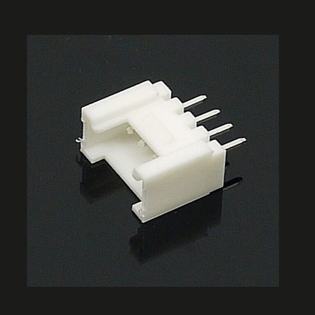
The universal 4 Pin connector is a white 4-pin buckled connector used on Stem, Twigs and Grove cables. The pin spacing is 2 mm. There are 10 connectors per bag. They can be used in DIY projects.
The official Raspberry Pi keyboard and hub is a standard 79-key German keyboard that includes an additional three USB 2.0 type A ports to power other peripherals. The keyboard is available in different language/country options as detailed below.
79-key DE keyboard
Three USB 2.0 type A ports for powering other peripherals
Automatic keyboard language detection
USB type A to micro USB type B cable included for connection to compatible computer
Ergonomic design for comfortable use
Compatible with all Raspberry Pi products
Kenmerken
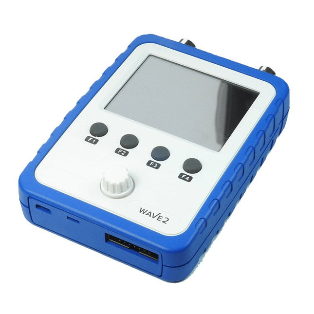
No. of Channels: 2
Bandwidth: 0-200 KHz per channel
Sensitivity range: 5 mV/DIV – 20 V/DIV (using x1 probe)
Maximum input voltage: 50 Vpk (using x1 probe)
Maximum real time sampling rate: 1 MS/s
Time Base range 10 us/DIV – 500 s/DIV
X-Y Display Feature: Yes
Function Generator Capability: Built-in 0 – 20 KHz (sine) dual channel DDS function generator
Display Resolution: 320 x 240 Color display
Display Size: 2.4?
Touch Display Capability: Yes
Battery powered and portable (battery not included in DIY Kit)
Specificaties
General
2.4” 320x240 color display
Touch panel operation
Y-X mode available
Built-in 2-channel DDS function generator
Light weight and portable
Vertical
Number of Channel: 2
Analog Bandwidth: DC – 200 KHz
Sensitivity: 5 mV/Div - 20 V/Div (with x1 probe)
Sensitivity error: < 5%
Resolution: 12-bit
Input Impedance: 1 M ohm / 25 pF
Maximum Input Voltage: 50 Vpk
Coupling: DC, AC
Horizontal
Max Real-time Sampling Rate: 1 Msps (per channel)
Timebase: 10 us/Div - 500 s/Div
Record Length: 1024 points
Trigger
Trigger Modes: Auto, Normal, Single
Trigger Types: Rising/falling edge
Trigger Position: 1/2 of buffer size
Trigger Source: Ch1, Ch2, External
Maximum external trigger voltage: 15 V
External trigger threshold: LVTTL
Function Generator
Number of channel: 2
Waveform type: Sine, Square, Saw-tooth, Stair
Frequency range: DC – 20 KHz (Sine)
Amplitude range: 0 – 3 V (peak value)
Offset: 0 V or +3.3 V
Duty Cycle: 0 – 100%
Phase: -360 – 360 degree
Power Supply
Powered on 3.7 V Li-ion battery or USB
Current consumption: ~30 0mA @ 3.7 – 5V
Internal batter charger (optional)
Automatic power off on battery
Battery running time: Appr. 3 hrs (when fully charged)
Other Features
Y-X display mode
On-screen measurement display
Save / recall up to 4 captures
Serial output of captured data
Serial port format: LVTTL, 115200 bps, 8N1
Built-in 1 KHz/3.3 V test signal
Physical
Dimension: 115 x 72 x 30 mm
Weight: 0.29 kg (excluding battery and probes)
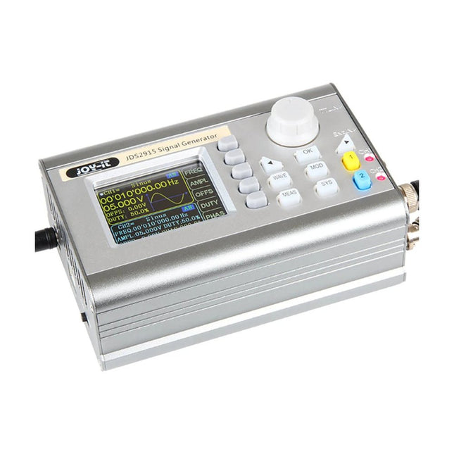
The JOY-iT JDS2915 is a powerful 2-channel signal generator capable of producing frequencies up to 15 MHz. It offers a wide range of waveforms to cater to diverse re quirements. With its compact de sign, it's perfect for on-the-go applications, and the ability to power it via a power bank ensures you're not confined to a single location.
Additionally, the device comes with an integrated 1-channel frequency counter, enhancing the precision and versatility of your measure ments and experiments.
Specificaties
Channels
2-channel Signal generator1-channel Frequency meter
Frequency Range
Sine: 0-15 MHzSquare, triangle: 0-15 MHzTTL, pulse: 0-6 MHz
Signal Forms
Sine, square, triangle, pulse, half / solid wave, exponential rise/ fall
Measuring Range Frequency Counter
1 MHz - 100 MHz
Frequency Accuracy
± 20 ppm
Frequency Stability
± 1 Ppm/3h
Sampling Rate
266 MSa/s
Display
2.4" TFT color LCD
Vertical Shaft Resolution
14 bits
Amplitude Range
<10 MHz : 0-20 Vpp>10 MHz : 0-10 Vpp
Amplitude Resolution
1 mV
Amplitude Stability
± 5%/5h
Amplitude Flatness
<10 MHz: ±5%>10 MHz: ±10%
Impedance of Output
50 Ω ±10%
Dimensions
145 x 95 x 55 mm
Weight
680 g
Inbegrepen
1x JOY-iT JDS2915 Signal Generator
1x Power supply unit
2x BNC crocodile clip cables
Downloads
Datasheet
Manual
Software
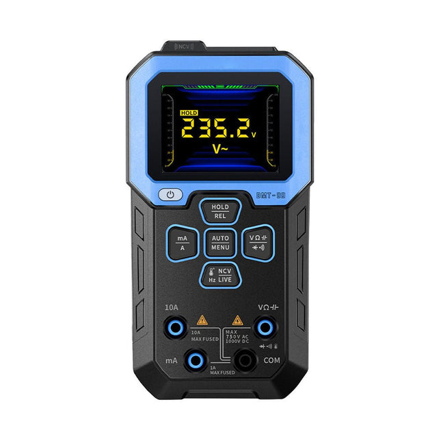
De FNIRSI DMT-99 is een intelligente digitale multimeter met 10000 counts, die een hoog meetbereik en een hoge resolutie biedt. Hij kan nauwkeurig AC/DC spanning, AC/DC stroom en 10 A stroom meten. Daarnaast kan hij ook worden gebruikt voor het testen van geleiding, capaciteit, frequentie, duty cycle, weerstand, diode, temperatuur, NCV, live wire detectie, enz.
Hij is geschikt voor gebruik bij een variëteit aan elektronische onderhoud, zoals bij machinebouw, laboratoria, auto's en huishoudelijke apparaten. Hij is uitgerust met een lithium accu van 1500 mAh en een 2,4-inch TFT-kleurenscherm met een resolutie van 240 x 320 pixels.
Specificaties
Functie
Bereik
Nauwkeurigheid
DC spanning
9,999 V / 99,99 V / 999,9 V
±(0,5% + 3)
AC spanning
9.999 V / 99,99 V / 750,0 V
±(1% + 3)
DC stroom
9999 uA / 99,99 mA / 999,9 mA / 9,999 A
±(1,2% + 3)
AC stroom
9999 uA / 99,99 mA / 999,9 mA / 9,999 A
±(1,5% + 3)
Weerstand
9,999 MΩ / 999,9 KΩ / 99,99 KΩ / 9,999 KΩ / 999,9 Ω
±(1,5% + 3)
99,99 MΩ
±(1,5% + 3)
Capaciteit
999,9 µF / 99,99 µF / 9,999 µF / 999,9 nF / 99,99 nF / 9,999 nF
±(2,0% + 3)
9,999 mF / 99,99 mF
±(5,0% + 3)
Frequentie
9,999 MHz / 999,9 KHz / 9999 KHz / 9,999 KHz / 999,99 Hz / 99,99 Hz / 9,999 Hz
±(0,1% + 3)
Temperatuur
-55~1300°C
±(2,5% + 3)
Diode
Ja
Continuïteitstest
Ja
NVC
Ja
Live wire detectie
Ja
Max waarde display
10000 counts
Accu capaciteit
1500 mAh
Afmetingen
155 x 80 x 36 mm
Gewicht
191 g
Inbegrepen
1x FNIRSI DMT-99 multimeter
2x Testpennen
1x USB-C oplaadkabel
1x Handleiding
Downloads
Manual
Firmware V2.4
De Elektor Laserkop transformeert de Elektor Sand Clock in een klok die de tijd op glow-in-the-dark-film schrijft in plaats van op zand. Naast het weergeven van de tijd kan het ook worden gebruikt om kortstondige tekeningen te maken. De 5 mW laserpointer, met een golflengte van 405 nm, produceert heldergroene tekeningen op de glow-in-the-dark-film. Voor het beste resultaat gebruikt u de kit in een slecht verlichte kamer. Waarschuwing: Kijk nooit rechtstreeks in de laserstraal!
De kit bevat alle benodigde componenten, maar het solderen van drie draden is vereist.
Opmerking: Deze kit is ook compatibel met de originele Arduino-gebaseerde Zandklok uit 2017. Voor meer details, zie Elektor 1-2/2017 en Elektor 1-2/2018.
Met de M.2 MicroMod connector is het aansluiten van uw ESP32 Processor een fluitje van een cent. Steek de edge-connector van uw processorbord in het M.2 slot en zet hem vast met een schroef (meegeleverd met alle Carrier Boards). Als u uw processor wilt vervangen door een gedegen draadloze optie, kijk dan zeker eens naar de MicroMod ESP32! De ESP32 bevat veel functionaliteit, waaronder de dual-core Tensilica LX6 microprocessor, 240MHz klokfrequentie, 520kB intern SRAM, geïntegreerde WiFi transceiver, geïntegreerde dual-mode Bluetooth, en hardware-encryptie (AES, SHA2, ECC, RSA-4096). Met dit MicroMod processorbord heb je toegang tot acht I/O-pinnen voor algemeen gebruik, analoge, digitale en PWM pinnen, alsook alle bekende interfaces zoals SPI, I2C, UART, en SDIO. Met 16 MB flash-opslag en een stroomopname van ongeveer 500µA in sleep-mode, is dit bord geschikt voor veel toepassingen. Eigenschappen Dual-core Tensilica LX6 microprocessor klokfrequentie tot 240 MHz 520 kB intern SRAM 128 Mbit / 16 MB flash storage Geïntegreerde 802.11 BGN WiFi transceiver dual-mode Bluetooth (classic and BLE) voedingsspanning 2,7 V tot 3,6 V 500µA stroom in sluimerstand 10-electrode capacitive touch support Hardware-accelerated encryption (AES, SHA2, ECC, RSA-4096) 1 x USB speciaal voor programmeren en debugging 1 x UART 2 x I2C 1 x SPI 7 x GPIO 2 x Digital Pins 2 x Analog Pins 2 x PWM Status LED VIN Level ADC
De HDS242 is een draagbare 2-in-1 multifunctionele tester, die kan worden gebruikt als een 2-kanaals oscilloscoop en multimeter. Hij beschikt over een contrastrijk 3,5-inch kleurendisplay dat geschikt is voor outdoor service, snelle metingen op locatie, voertuigonderhoud, spanningsdetectie, en meer.Kenmerken
Oscilloscoop + multimeter
3,5-inch LCD-kleurenscherm met hoge resolutie en hoog contrast – geschikt voor gebruik buitenshuis
18650 lithium accu – kan tot 6 uur continu werken
USB Type-C interface - ondersteuning voor powerbank en PC-aansluiting
Zelfkalibratie functie
SCPI ondersteund – faciliteer secundairy development
Specificaties
Oscilloscoop
Bandbreedte
40 MHz
Kanalen
2-kanaals oscilloscoop
Sample frequentie
250 MSa/s
Acquisition modi
Normaal, Piekdetectie
Record Lengte
8K
Display
3,5-inch LCD
Golfvorm refresh rate
10.000 wfrms/s
Ingangssignaal
DC, AC en Ground
Ingangsimpedantie
1 M? ±2%, parallel aan 16pF ±10pF
Probe dempingen
1X, 10X, 100X, 1000X, 10000X
Max. Ingangsspanning
400 V (DC+AC, PK-PK, 1M? ingangsimpedantie) (10:1 probe demping)
Bandbreedte (typical)
20 MHz
Horizontale schaal
5ns/div - 1000s/div, in stappen van 1 - 2 - 52ns/div - 1000s/div, in stappen van 1 - 2 - 55ns/div - 1000s/div, in stappen van 1 - 2 - 52ns/div - 1000s/div, in stappen van 1 - 2 - 5
Verticale gevoeligheid
10mV/div - 10V/div
Verticale resolutie
8 bits
Trigger Type
Edge
Trigger Modi
Auto, Normal, Single
Automatische Meting
Frequency, Period, Amplitude, Max, Min, Mean, PK-PK
Cursor meting
? V, ? T, ?T & ?V tussen cursors
Multimeter
Max resolutie
20.000 counts
Test modi
Spanning, Stroom, Weerstand, Capaciteit, Diode en Continuïteitstest
Ingangsimpedantie
10 M?
Max ingangsspanning
AC: 750 V | DC: 1000 V
Max ingangsstroom
DC: 10 A | AC: 10 A
Diode
0-2 V
Overig
Connectiviteit
USB Type-C
Afmetingen
198 x 96 x 38 mm (7,68 x 3,74 x 1,5')
Gewicht
600 g (zonder accu)
Inbegrepen
1x OWON HDS242 Oscilloscoop
1x tasje
1x probe
1x netsnoer
1x probe adjust
1x USB-kabel
1x voedingsadapter
1x set multimeter probe kabels (rode en zwarte)
1x set oscilloscoop probe leads (BNC naar Krokodil)
1x gebruikershandleiding (Engels)
Downloads
User Manual for HDS200 Series
SCPI Protocol for HDS200 Series
Quick Guide for HDS200 Series
PC Software for OWON HDS200 Series
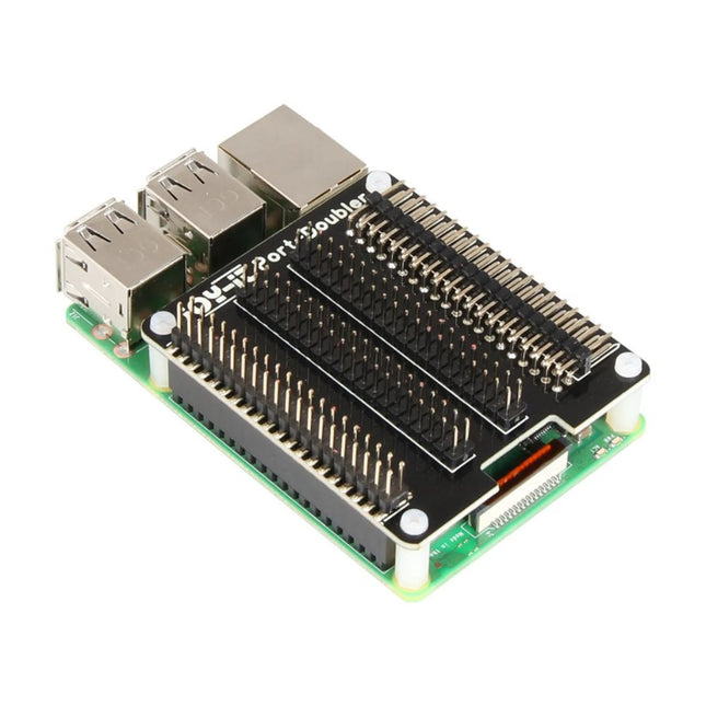
MODEL Port-Doubler FUNCTION Provides 4 GPIO bars CONNECTIVITY Attaches directly to the existing GPIO bar of the Raspberry Pi DIMENSIONS 55 x 66 mm WEIGHT 30 g ITEMS SHIPPED Port-Doubler, Mounting material EAN 4250236817057 ARTICLE NO. RB-Port-Doubler
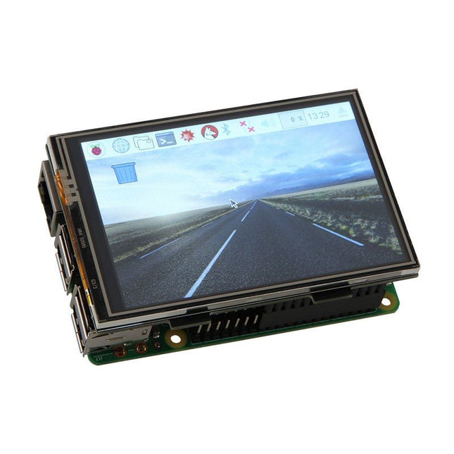
With the 3.5 inch large TFT touch screen display, you can build a mini tablet PC based on a Raspberry Pi. The display, with a maximum resolution of 480x320 pixels, is simply plugged into the existing GPIO connectors.
Specificaties
Display: 3.5" (8.89 cm)
Resolution: 480x320 pixels
Touchscreen Type: Resistive
Touch screen controller: XPT2046
Colors: 65536
Backlight: LED
Connection: GPIO header
Aspect ratio: 8:5
Display Size: 85 x 56 mm
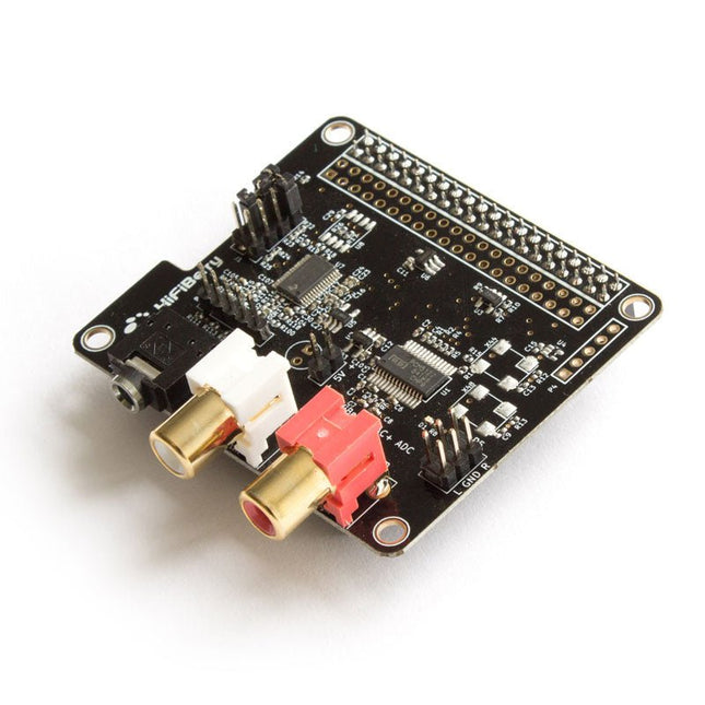
Features
Stereo input and output
Dedicated 192 kHz / 24-bit high-quality Burr-Brown DAC
Dedicated 192 kHz / 24-bit high-quality Burr-Brown ADC
Hardware volume control for DAC. The output volume can be controlled using “alsamixer” or any application that supports ALSA mixer controls.
Connects directly onto the Raspberry Pi.
No soldering required.
Compatible with all Raspberry Pi models, that have a 40-pin GPIO connector
No additional power supply required.
Three ultra-low-noise linear voltage regulators.
HAT compliant, EEPROM for automatic configuration.
Gold plated RCA output connectors.
Includes 4 M 2.5 x 12 mm spacers.
Analogue input, phone jack 3.5 mm
Analogue output RCA
Analogue output (P5)
Input configuration jumper (J1)
Connector for balanced input (P6)
Please note: Layout and components might change without further notice. Balanced/unbalanced input connector (P6)The 5-pin connector can be used to connect a balanced input. Please note that the balanced input has to be selected with the jumpers and will always have a 12 dB gain. It shouldn't be used with line-level inputs.Pin 1 is on the left.
right +
right –
GND
left –
left +
Output connector (P5)The output connector realizes connections to external components like an amplifier.Pin 1 is on the top left.
+5V
1
2
R
GND
3
4
GND
+5V
5
6
L
Input gain settings (J1)The jumper block is responsible for the input configuration. It is recommended to use the default setting without additional input gain. 32 dB gain can be used to connect dynamic microphones.Jumpers are numbered from top to bottom.
1
2
3
4
function
1
0
0
–
0 dB gain
0
1
1
–
12 dB gain
0
1
0
–
32 dB gain
0
0
1
–
balanced input, 12 dB gain
Specifications
Maximum input voltage: 2.1 Vrms - 4.2 Vrms for balanced input
Maximum output voltage: 2.1 Vrms
ADC signal-to-noise ratio: 110 dB
DAC signal-to-noise ratio: 112 dB
ADC THD+N: -93 dB
DAC THD+N: -93 dB
Input voltage for lowest distortions: 0.8 Vrms
Input gain (configurable with Jumpers): 0 dB, 12 dB, 32 dB
Power consumption: < 0.3 W
Sample rates: 44.1 kHz - 192 kHz
In order to use the HiFiBerry DAC + ADC, your Raspberry Pi Linux kernel must be at least version 4.18.12. Click here to learn how to update the Raspberry Pi kernelUsing microphones with the DAC+ ADCThe DAC+ ADC is equipped with a stereo analogue input that can be configured for a wide range of input voltages. It performs best with line-level analogue sources. However, it is also possible to use it as a microphone input.
You can only use dynamic microphones. Microphones that require a power supply are not supported.
The microphone output voltage is very low. This means you need to amplify it. The DAC+ ADC has the necessary pre-amplifier already equipped. You will have to set the jumpers correctly.
The sound from the input won’t be played back automatically on the output. You will have to use some software that reads the input and outputs it again.
Setting the correct input amplifier settings for a microphoneBy default, the input sensitivity is matched for line-level audio sources. This is done via a jumper on the J1 header.In order to use a microphone, the jumper needs to be set up as shown below.Audio input to outputThere is no direct connection between the input and the output. That leads to the input from the connected microphone to not be played back automatically. If you want to hear it on the output, you need to use the command line tool alsaloop can be used for this.
Tout sur les protocoles et leur mise en œuvre avec Arduino
Initialement destiné aux véhicules routiers, le réseau CAN (« Controller Area Network ») et son successeur le réseau CAN FD (« Flexible Data ») ont vu leurs champs d’application s’élargir à de nouveaux domaines. L’industrie propose de nombreux modules microcontrôleurs dotés d’une interface CAN et/ou CAN FD. L’environnement de développement Arduino a démocratisé la programmation de ces modules et il existe des bibliothèques qui implémentent un pilote CAN et/ou un pilote CAN FD.
La première partie dresse un rapide historique des réseaux CAN et CAN FD et expose la problématique des lignes de transmission en abordant succinctement leur théorie et présentant des résultats de simulation Spice.
La deuxième partie est consacrée au réseau CAN, en détaillant successivement la fonction logique du réseau, les transcepteurs, les contrôleurs, la topologie la plus classique (le bus) et d’autres moins courantes, les répéteurs et les passerelles. Les aspects particuliers du protocole, tels que le bit stuffing, l’arbitrage, les trames d’erreur, la détection des erreurs sont exposés. La discussion de la fiabilité du protocole est illustrée par des exemples mettant en évidence ses faiblesses.
La troisième partie présente le protocole CAN FD, ses deux variantes CAN FD ISO et CAN FD non ISO, leurs fiabilités, leurs faiblesses, mises en évidence par des exemples. Différents transcepteurs et contrôleurs CAN FD sont décrits.
La quatrième partie est dédiée aux applications : comment utiliser les services d’un pilote, concevoir une messagerie, utiliser un analyseur logique. Deux exemples d’application terminent cette partie.
Ce livre s’adresse aux amateurs et aux ingénieurs non spécialistes pour comprendre les possibilités qu’offre un réseau CAN et comment on le met en œuvre. Un enseignant trouvera des informations pour approfondir ses connaissances et pour concevoir des travaux pratiques. Une connaissance des microcontrôleurs, de leur programmation, de l’électronique numérique aidera à la lecture des schémas. La connaissance du langage C++ et du langage de simulation électronique Spice facilitera la compréhension des programmes qui sont décrits dans le livre. Tous les codes source sont disponibles sur le dépôt GitHub de l’auteur.
Téléchargements
GitHub
De USB-CAN-FD is een hoogwaardige industriële USB-naar-CAN-FD-adapter, CAN/CAN-FD bus communicatie-interfacekaart en CAN/CAN-FD protocoldata analysator. Aan boord dubbele onafhankelijke CAN-FD interfaces met elektrische isolatie en meerdere beveiligingscircuits. Ondersteunt Windows, wordt geleverd met stuurprogramma's, CAN-FD Tools gerelateerde software, secundaire ontwikkelingsvoorbeelden en tutorials.Het kan via een USB-poort worden aangesloten op een pc of industriële besturingshost om transceiverbesturing, gegevensanalyse, verzameling en bewaking van CAN/CAN-FD-busnetwerk te realiseren. Het apparaat is compact en gebruiksvriendelijk en kan worden gebruikt voor het leren en debuggen van de CAN/CAN-FD-bus en voor secundaire ontwikkeling en integratie in diverse industriële, energiecommunicatie- en intelligente besturingstoepassingen die CAN/CAN-FD-bus communicatie vereisen.Specificaties
Soort product
Industriële kwaliteit: USB naar CAN-FD interfaceconverter, CAN/CAN-FD bus communicatie-interfacekaart, CAN/CAN-FD protocoldata analysator
USB
Bedrijfsspanning
5 V (rechtstreeks van de USB-poort zonder externe voeding)
Aansluiting
USB-B
CAN/CAN FD-interface
CAN/CAN FD-kanaal
Tweekanaals: CAN1 en CAN2 (onafhankelijk en volledig geïsoleerd, isolatie spanning: 3000 V DC)
Aansluiting
CAN-bus schroefklem (OPEN6 5,08 mm steek)
Afsluitweerstand
Elk CAN/CAN-FD-kanaal heeft twee ingebouwde 120? afsluitweerstanden, die kunnen worden ingeschakeld met een schakelaar
Baudrate
100Kbps~5Mbps (configureerbaar via software)
Protocol ondersteuning
CAN2.0A, CAN2.0B en ISO 11898-1 CAN-FD protocol V.1.0
Overdrachtssnelheid
De ontvangst- en verzendsnelheid van elk CAN/CAN-FD-kanaal kan 20000 frames/s en 5000 frames/s bereiken.
Buffer voor verzenden
1500 frames ontvangstbuffer en 64 frames zendbuffer per kanaal (automatisch opnieuw zenden als de verzending mislukt)
Indicatoren
PWR
Voedingsspanning
SYS
Systeemstatus, normaal uit; blijft aan als er een bus fout is
CAN1
CAN1-kanaalindicator (knippert bij verzenden en ontvangen van data)
CAN2
CAN2-kanaalindicator (knippert bij verzenden en ontvangen van data)
Systeemondersteuning
Windows
Windows XP/7/8/10/11 (32/64 bits); biedt nog geen ondersteuning voor Linux; de bijbehorende stuurprogramma's zijn in ontwikkeling.
Bedrijfstemperatuur
?40 tot +85°C
Materiaal behuizing
Aluminium behuizing + 3D vlamwerende isolatieplaten aan beide zijden (Dit ontwerp kan een betere bescherming bieden tegen elektrische ontladingen, verbetert de veiligheid van het product en verlengt de levensduur)
Afmetingen
104 x 70 x 25 mm
Inbegrepen
Waveshare USB-CAN-FD
USB-A naar USB-B kabel
4-pins kabel
Schroevendraaier
DownloadsWiki
The PCW10A soldering mat is the ultimate solution for any soldering or repair project. Measuring 450 x 300 mm, this silicone mat provides a generous work surface that is heat-resistant up to 450°C, making it ideal for use with a range of (soldering) tools and equipment. It is the perfect size for your workbench and provides ample space for all your tools and components.
The PCW10A soldering mat comes with several convenient features to make your repair work easier and more efficient. The built-in storage boxes provide a convenient place to keep your tools and components organized, while the powerful magnets hold small parts securely in place. These features ensure that you can work more efficiently and effectively, reducing the risk of lost or misplaced items.
The PCW10A soldering mat also features a non-slip surface that provides a stable and secure work environment, preventing your equipment from slipping or sliding during use. Additionally, the mat is easy to clean, allowing you to maintain a hygienic workspace that is free of debris and other contaminants. In addition, the mat also features a printed grid to help you measure and cut materials accurately.
Whether you are a professional technician or a DIY enthusiast, the PCW10A soldering mat is an essential tool for anyone who needs a reliable and durable work surface for their repair and soldering projects. With its durable construction, ample workspace, and convenient storage options, you can tackle any project with confidence and ease.
Features
Silica gel working mat (blue)
Size: 450 x 300 mm
Edge thickness: 6.5 mm
Various magnetic sections
3 storage boxes
Heat-resistant 450°C
Kenmerken
4 1/2 bit resolutie (20000 counts)
Datalogger
Multimeter
Thermometer
True RMS test ondersteund
BLE 4.0 draadloze transmissie, stabieler, minder stroomverbruik
Ingebouwde offline opnamefunctie
Grafiek en Diagram modus helpen om de datatrend te analyseren
Met de zaklampfunctie om licht in de duisternis te brengen
Ondersteuning van NCV (non-contact voltage sense), een draadloze spanningszoeker
Brede ondersteuning op Android, iOS, Windowss
Inbegrepen
OWON OW18E Multimeter
Korte handleiding
Multimeter snoeren
K-type Thermokoppel
Schroefkop houder
App Downloaden
De Bluetooth functie van deze multimeter is compatibel met Android-app versie 1.5.8.0 of nieuwer.
Gebruik de QR code in de doos of ga naar http://files.owon.com.cn/bluetooth.
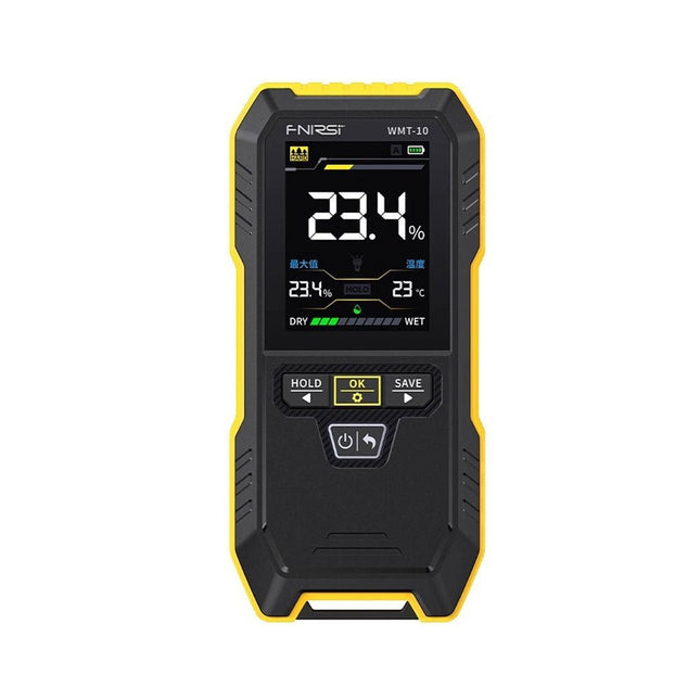
De WMT-10 Inductieve Houtvochtmeter beschikt over een 2,4-inch HD-kleurenscherm, speciaal ontworpen om tegemoet te komen aan de behoeften van de houtverwerkende industrie en houtgebruikers. Dit geavanceerde apparaat biedt nauwkeurige metingen van het houtvochtgehalte en ondersteunt vier veelzijdige meetmodi: hardhout, zachthout, gipsmuur en bakstenen muur.
Specificaties
Meettype
Niet-destructief / pinloos / inductief / contactloos testen
Weergave
2,4" TFT-kleurenscherm
Resolutie
0,1%
Diepte meten (max)
17 mm
Sensorgrootte
40,5 x 40,5 mm
Meetbereik
Gipsmuur: 0~25%
Bakstenen muur: 0~43%
Zachthout: 0~75%
Hardhout: 0~75%
Meetfout
±1,5%
Vochtigheidsalarm
Geluidsalarm / Kleuralarm
Automatische uitschakeling
5/10/15 minuten
Gegevens opslaan en bekijken
Bewaar en bekijk maximaal 30 gegevenssets
Voeding
1000 mAh lithiumbatterij
Bedrijfstemperatuur
0~40℃
Afmetingen
206 x 99 x 44 mm
Gewicht
238 g
Inbegrepen
1x FNIRSI WMT-10 houtvochtmeter
1x USB-kabel
1x Manual
Downloads
Manual
Il n'existe que quelques séries de 50 projets passionnés pour initier la programmation JAL et maîtriser les microcontrôleurs PIC. La simple LED clignotante à la vision artificielle, l'alarme laser à la souris USB taquine, l'indicateur de niveau capacitif et le gradateur de lumière, ces projets s'appuient sur des consignes et des distrayants. Il est nécessaire d'étudier les techniques de base utilisées pour communiquer la commande d'un relais, et les caractéristiques des signaux utilisés par différents capteurs (constitués par l'exemple d'un codeur rotatif), la communication par bus I²C, SPI, RS232, USB , affiches de 7 segments et avec le bus CAN. On y apprend à pratiquer la commande de largeur d'impulsion, la conversion analogique-numérique et inversement, le traitement des interruptions, et bien des astuces.
L'auteur doit être enthousiaste et désireux de progresser dans son appréciation.
Abordez-le comme une récréatif et pédagogique : assemblez et utilisez les projets proposés. Les explications claires, les schémas et les photographies servent à révéler une activité enrichissante et captivante.
Considérez la conception, le style et les détails du projet. A l'aide de microcontrôleurs et de l'utilisation de compositions et de projets, l'exploitation des techniques est pleinement expliquée. Avec l'augmentation de l'apprentissage après la spécification, l'auteur continue avec les contrôles : le 16f877A, le 18f4455, et le18f4685. N'hésitez pas à nous contacter pour plus d'informations sur le projet et à utiliser l'adaptateur pour garantir une bonne utilisation. Vous apprendrez d'ailleurs comment transposer vos programmes d'un microcontrôleur à Utre. La procédure de transfert du programme du microcontrôleur via le programmateur Wisp648 est la procédure de test finale.
C'est aussi un guide de référence, comprenant des sources d'informations : une explication de la durée de la programmation des JAL et de l'utilisation des bibliothèques d'extension. Les outils de programmation (environnement de développement JALedit/XWisp, bibliothèques JAL, programmes décrits) sont téléchargeables gratuitement (voir ci-dessous). L'index permet de retrouver rapidement un projet et donc les principales commandes dans le contexte. En tant qu'expert, vous êtes le guide principal !
Dit uiterst nauwkeurige, antistatische pincet met zwarte ESD-coating kan in de elektronica worden gebruikt voor het plaatsen van SMD-componenten bij het solderen en voor het repareren van smartwatches, smartphones, tablets, pc's enz. Het is ideaal voor het oppakken van kleine componenten op moeilijk bereikbare plaatsen plaatsen bereiken.
Specificaties
Lengte
135 mm
Breedte
9 mm
Elektor GREEN en GOLD leden kunnen deze uitgave hier downloaden.
Nog geen lid? Klik hier om een lidmaatschap af te sluiten.
Kleine warmtebeeldcameraeen op Arduino UNO gebaseerde DHZ-oplossing
Project-update #3: ESP32-gebaseerde energiemeterintegratie en test met Home Assistant
2024: een AI-odysseeobjectdetectie verbeteren met verfijnde technieken
De Raspberry Pi gaat AInieuwe kit bevat M.2 HAT+ met AI-versneller
Sensoren voor weerstationswat is de beste keuze?
Lees uw analoge watermeter uit met AI (1)koppel uw oude watermeter met het IoT!
GSM-alarmdraadloze garagebeveiliging
Low-power Thread-devices geoptimaliseerd en onder de loep genomenweinig vermogen... weinig inspanning?
Uit het leven gegrepende genderkloof
Zelfbouw-nevelkamermaak onzichtbare straling zichtbaar
SparkFun Thing Plus Mattereen veelzijdig Matter-gebaseerd IoT development board
IoT-retrofittenRS232-apparaten klaarstomen voor Industry 4.0
Stimuleer het IoT met 8-bit MCU’s
Technologie stimuleert duurzaamheidvooruitgang leidt in veel toepassingen tot efficiënter energiegebruik
AWS voor Arduino en co. (1)AWS IoT ExpressLink in de praktijk
Luchtstroomdetector met alleen een Arduinozonder externe sensoren!
Lekdetectorverbonden met de Arduino-cloud
Kristallenvreemde onderdelen
Universele logger voor de tuinAI-tuinieren komt een stapje dichterbij
Analoge 1kHz-generatorsinussen met geringe vervorming
Miletus: webapps offline gebruikeninclusief toegang tot het systeem en het apparaat!
Van 4G naar 5Gis het echt zo eenvoudig?
Alle begin......gaat symmetrisch
Deze Crowtail serie 4G module is een krachtige LTE Cat1 draadloze module. Hij maakt gebruik van de SIM A7670E communicatiemodule van Simcom, en communiceert via een UART-interface die 4G datatransmissie en spraakcommunicatie mogelijk maakt. De unit ondersteunt meerdere LTE-banden, waaronder B1 / B3 / B5 / B7 / B8 / B20, evenals WCDMA- en GSM-netwerken. Daarnaast ondersteunt hij verschillende protocollen zoals TCP/IP, FTP, HTTP en meerdere satelliet navigatiesystemen zoals GPS, GLONASS en BDS.
De module wordt geleverd met een interface voor het opladen, en kan worden gevoed met een 3,7 V lithium accu of via een 5 V USB-C interface. Hij heeft ook een 3,5 mm koptelefoonaansluiting zodat hij, door een hoofdtelefoon met een microfoon aan te sluiten, kan worden gebruikt voor het maken en ontvangen van telefoongesprekken. Het compacte formaat maakt het eenvoudig om hem te integreren in verschillende IoT-apparaten, en te voldoen aan de eisen van diverse toepassingen. Ook het lage stroomverbruik en de betrouwbare werking behoren tot de redenen waarom hij veel wordt gebruikt bij IoT, smart home, automotive en industriële besturing.
Kenmerken
Bevat de A7670E communicatiemodule, waardoor 4G-gegevensoverdracht en spraakcommunicatie mogelijk zijn met laag stroomverbruik en hoge betrouwbaarheid
Ondersteunt meerdere LTE-banden, waaronder B1 / B3 / B5 / B7 / B8 / B20, evenals WCDMA- en GSM-netwerken
Ondersteunt verschillende protocollen zoals TCP/IP, FTP, HTTP en meerdere satelliet navigatiesystemen zoals GPS, GLONASS en BDS
Wordt geleverd met een interface voor het opladen, en een hoofdtelefoonaansluiting die kan worden gebruikt voor het maken en ontvangen van telefoongesprekken door een hoofdtelefoon met microfoon aan te sluiten
Klein maar krachtig, zíjn compacte formaat maakt het gemakkelijk hem te integreren in verschillende IoT-apparaten.
Specificaties
Hoofd processor: SIM A7670E
LTE-FDD: B1 / B3 / B5 / B7 / B8 / B20
GSM: 900/1800 MHz
GSM/GPRS vermogensklasse
EGSM900: 4 (33 dBm ±2 dB)
DCS1800: 1 (30 dBm ±2 dB)
EDGE vermogensklasse:
EGSM900: E2 (27 dBm ±3 dB)
DCS1800 : E1 (26 dBm +3 dB / -4 dB)
LTE vermogensklasse: 3 (23 dBm ±7 dB)
Voedingsspanning: 4 V ~ 4,2 V
Werkspanning: 3,8 V
LTE (Mbps): 10 (DL) / 5 (UL)
GPRS/EDGE (Kbps): 236.8 (DL) / 236.8 (UL)
Protocol: TCP/IP / IPV4 / IPV6 / Multi-PDP / FTP / FTPS / HTTP / HTTPS / DNS
Communicatie interface: USB / UART
Firmware upgrade: USB / FOTA
Ondersteunde telefoonboek types: SM / FD / ON / AP / SDN
Interfaces: 1x aan/uit-knop, 1x BAT, 1x UART, 1x USB-C, 1x SIM-kaart slot
Afmetingen: 35 x 50 mm
Inbegrepen
1x Crowtail-4G SIM-A7670E
1x 4G GSM NB-IoT antenne
1x GPS keramische antenne
Downloads
Wiki
A7670 AT Command Manual
A7670 Datasheet
Source Code