Physical Products
-

Arduino Officiële Arduino USB-C kabel (2-in-1)
Vanaf nu kunt u uw Arduino boards aansluiten met de officiële Arduino USB kabel. Met deze data USB kabel kan uw Arduino board eenvoudig worden verbonden met een door u gekozen apparaat, via een USB-C naar een USB-C met een USB-A adapter. De Arduino USB kabel heeft een nylon gevlochten mantel in de typische Arduino kleuren wit en groenblauw. De connectoren hebben een aluminium omhulsel dat uw kabel beschermt tegen schade en er meteen ook cool uitziet. Lengte: 100 cm Aluminium omhulsel met logo Nylon gevlochten mantel in wit en groenblauw
€ 12,95
Leden: € 11,66
-
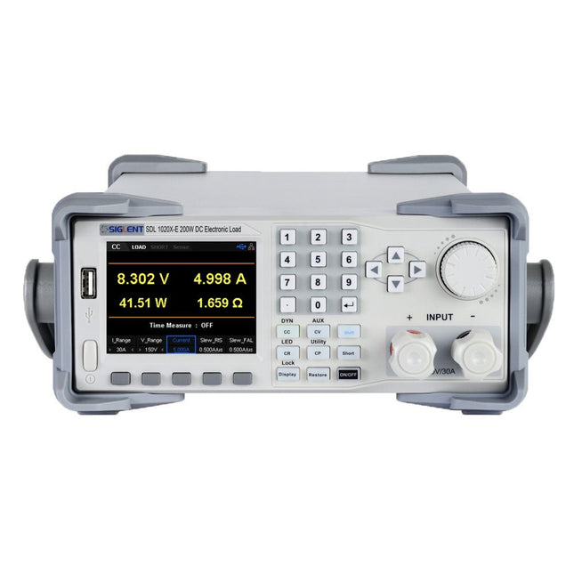
Siglent Siglent SDL1020X-E DC Electronic Load (200 W)
De Siglent SDL1020X-E DC meetsnoeren hebben een meetresolutie van 0,1 mV/0,1 mA en de basis SDL1000X-E serie heeft een resolutie van 1 mV/1 mA en instelbare stroom flankstijgtijden van 0,001 A/?s~2,5 A/?s. Voor communicatie en bediening op afstand bevat de SDL serie S232/USB/LAN interfaces. De SDL1020X-E levert stabiliteit over een breed scala van toepassingen en kan aan allerlei test vereisten voldoen. o.a: Voeding, batterij/handapparaat ontwerp, industrie, LED verlichting, auto-elektronica, en ruimtevaart. Kenmerken SDL1020X-E (één kanaal): DC 150 V/30 A, totaal vermogen 200 W 4 Statische modes / Dynamische mode: CC/CV/CR/CP CC Dynamische stand: Continu, gepulseerd, omgeschakeld CC Dynamische stand: 25 kHz, CP Dynamische stand: 12,5 kHz, CV Dynamische modus: 0,5 Hz Meetsnelheid van spanning en stroom: tot 500 kHz Instelbaar bereik van de stijgtijd van de stroom: 0,001 A/us~2,5 A/us Min. afleesresolutie: 0,1 mV, 0,1 mA Kortsluit-, batterijtest-, CR-LED modus-, en fabriekstestfuncties 4-draads SENSE compensatie mode functie List functie ondersteunt het bewerken van wel 100 stappen Programmeerfunctie ondersteunt 50 groepen stappen OCP, OVP, OPP, OTP en LRV beveiliging Externe analoge regeling Spanning, stroom bewaking via 0-10 V 3,5 inch TFT-LCD scherm, geschikt voor gelijktijdige weergave van meerdere parameters en toestanden Ingebouwde RS232/USB/LAN communicatie interface, USB-GPIB module (optioneel) Trendgrafiek van golfvormen en gemakkelijk te gebruiken functies voor het opslaan en oproepen van bestanden Inclusief PC software: Ondersteunt SCPI, LabView aandrijving Inbegrepen 1x Siglent SDL1020X-E DC programmeerbare belasting 1x Snelstartgids 1x Garantiekaart 1x Netsnoer 1x USB kabel Downloads Datasheet Manual Programming Guide PC Software
€ 531,19
-
FNIRSI FNIRSI DPS150 DC-voeding (150 W)
De FNIRSI DPS150 is een krachtige, instelbare DC-voeding met een USB-C-ingangsinterface en meerdere voedingsmodi, waardoor een nauwkeurige aanpassing van de uitgangsspanning (0-30 V) en stroom (0-5 A) mogelijk is. Het biedt een efficiënte, laag verbruik en stabiele output, uitgerust met meerdere veiligheidsbeschermingsfuncties, waaronder overspanning, overstroom, overbelasting, oververhitting en omgekeerde verbinding. Het kan flexibel worden toegepast op de seriële verbinding van meerdere apparaten, met een rijke en gebruiksvriendelijke weergave en bediening, een compact en draagbaar ontwerp en voldoet aan verschillende toepassingsbehoeften. Kenmerken 30 V, 5 A, 150 W variabel gelijkstroomvermogen met 0,01 V, 0,001 A precisie, CC/CV-modi en <20 mV rimpel om gevoelige elektronica te beschermen. Ondersteunt pc-, QC- en DC-ingangen met programmeerbare uitgangen en 6 vooraf ingestelde spannings-/stroominstellingen. Compatibel met 4 mm banaanstekkers, U-vormige aansluitingen en koperdraden voor diverse apparatuur. 8 veiligheidsmechanismen, waaronder bescherming tegen overspanning, stroom, kortsluiting en oververhitting. 2,8-inch HD IPS-scherm met 90° flip-, numerieke en curve-displays voor eenvoudige monitoring. Klein, ruimtebesparend ontwerp voor gebruik in laboratoria, reparaties en doe-het-zelf-projecten. Specificaties Ingangsspanning 5~32 V DC Ingangsstroom 100 mA-5 A Uitgangsspanning 0-30 V Uitgangsstroom 0~5 A Uitgangsvermogen 0-150 W Input way PD-snellader QC snellader Powerbank DC-voedingsadapters Bedrijfsomgeving 0-40°C Belastingsregeling 0,49% Efficiëntie bij volledige belasting 96,30% Display 2,8 inch (320 x 240) Afmetingen 106 x 76 x 28 mm Gewicht 178 g Inbegrepen 1x DPS150 voeding 2x Krokodillenklemdraden (zwart en rood) 1x Micro-USB-kabel 1x Manual Downloads Manual Firmware V0.0.1
€ 59,00
-

Elektor Publishing Tektronix 7000 Series Mainframes
The Most Iconic Oscilloscopes in Electronics History The 7000 Series was the most iconic family of oscilloscopes in the history of technology. Introduced in 1969 by Tektronix, the sector’s leader at the time, this remarkable line of instruments defined an era and became a benchmark for generations of engineers, researchers, and technicians. Throughout the 1970s and well beyond, 7000-Series oscilloscopes were a constant presence in laboratories, universities, and industrial facilities around the world. Their modular plug-in architecture, exceptional flexibility, and outstanding performance embodied the engineering philosophy that made Tektronix synonymous with accuracy, innovation, and reliability. This book offers an in-depth exploration of the 7000-Series oscilloscopes, combining historical context, technical analysis, and practical insight into their design and restoration. Conceived as a continuation of Tektronix Epic Oscilloscopes, this work expands the subject into two volumes: the first devoted to mainframes and core technologies, the second focused entirely on plug-ins.
€ 69,95
Leden: € 62,96
-

OWON OWON VDS1022I 2-ch USB-oscilloscoop (25 MHz)
De OWON VDS1022I 2-kanaals USB-oscilloscoop (25 MHz) is een oscilloscoop voor gebruik met een computer. Hij wordt van voeding voorzien via USB en heeft een klein formaat, waardoor hij gemakkelijk mee te nemen is. De oscilloscoop is zeer betaalbaar. Hij heeft een afgeschermde USB-aansluiting, waardoor storing wordt verminderd en de computer wordt beschermd tegen overspanning. De multipoort op de scoop kan worden gebruikt voor externe triggering, trigger out of Pass / Fail uitgang.Kenmerken 25 MHz bandbreedte, en max. 1 GS/s real-time sample rate 10M recordlengte Gebruiksvriendelijke UI: FFT, of X-Y, en golfvorm 2 weergaven op hetzelfde scherm Multi-trigger optie: flank, video, slope, puls en afwisselend USB isolatie - minder signaalverstoring, meer pc-bescherming USB busvoeding en LAN afstandsbediening (optioneel) Ultradunne behuizing, gemakkelijk draagbaar Specificaties Bandbreedte 25 MHz Kanalen 2+1 (multi) Sample Rate 100 MSa/s Horizontal schaal (s/div) 5 ns/div?100s/div, in stappen van 1?2?5 Opname lengte 5K Max ingangsspanning 400 V (PK - PK) (DC+AC, PK - PK) 40 V (PK - PK) (DC+AC, PK - PK) Verticale resolutie (A/D) 8 bits (2 kanalen tegelijkertijd) Model VDS1022I Verticale gevoeligheid 5 mV/div?5 V/div Triggertype Edge, Pulse, Video, Slope, en Afwisselend Trigger mode Auto, Normaal, en Enkelvoudig Acquisition Mode Sample, Peak Detect, en Gemiddeld Golfvorm berekeningen ?, ?, ×, ÷, invert, FFT Communicatie Interface USB 2.0 (geïsoleerd) Multifunctioneel Interface Signaltype Level standard TTL Voeding 5,0 V/1 A Stroomverbruik ?2.5 W Afmetinegn (B × H × D) 170 x 120 x 18 mm Gewicht 0,26 kg Inbegrepen 1x OWON VDS1022I oscilloscoop 1x CD-ROM 1x Snelstartgids 2x Oscilloscoop probe 1x Probe 1x Voedingsadapter 1x USB kabel 1x Silicone beschermers voor de behuizing 1x Stroomkabel Downloads Datasheet Gebruiksaanwijzing SCPI protocol USB driver
€ 119,00
-

Elektor Publishing The BeagleY-AI Handbook
A Practical Guide to AI, Python, and Hardware Projects Welcome to your BeagleY-AI journey! This compact, powerful, and affordable single-board computer is perfect for developers and hobbyists. With its dedicated 4 TOPS AI co-processor and a 1.4 GHz Quad-core Cortex-A53 CPU, the BeagleY-AI is equipped to handle both AI applications and real-time I/O tasks. Powered by the Texas Instruments AM67A processor, it offers DSPs, a 3D graphics unit, and video accelerators. Inside this handbook, you‘ll find over 50 hands-on projects that cover a wide range of topics—from basic circuits with LEDs and sensors to an AI-driven project. Each project is written in Python 3 and includes detailed explanations and full program listings to guide you. Whether you‘re a beginner or more advanced, you can follow these projects as they are or modify them to fit your own creative ideas. Here’s a glimpse of some exciting projects included in this handbook: Morse Code Exerciser with LED or BuzzerType a message and watch it come to life as an LED or buzzer translates your text into Morse code. Ultrasonic Distance MeasurementUse an ultrasonic sensor to measure distances and display the result in real time. Environmental Data Display & VisualizationCollect temperature, pressure, and humidity readings from the BME280 sensor, and display or plot them on a graphical interface. SPI – Voltmeter with ADCLearn how to measure voltage using an external ADC and display the results on your BeagleY-AI. GPS Coordinates DisplayTrack your location with a GPS module and view geographic coordinates on your screen. BeagleY-AI and Raspberry Pi 4 CommunicationDiscover how to make your BeagleY-AI and Raspberry Pi communicate over a serial link and exchange data. AI-Driven Object Detection with TensorFlow LiteSet up and run an object detection model using TensorFlow Lite on the BeagleY-AI platform, with complete hardware and software details provided.
€ 44,95
Leden: € 40,46
-

Pinecone Pinecone BL602 Evaluation Board
Features Build in USB to Serial interface Build-in PCB antenna Powered by Pineseed BL602 SoC using Pinenut model: 12S stamp 2 MB Flash USB-C connection Suitable to breadboard BIY project On board three color LEDs output Dimensions: 25.4 x 44.0 mm Note: USB cable is not included.
€ 8,95€ 3,50
Beste prijs
-

NXP Semiconductors NXP FRDM-MCXN947 Development Board
The FRDM-MCXN947 is a compact and versatile development board designed for rapid prototyping with MCX N94 and N54 microcontrollers. It features industry-standard headers for easy access to the MCU's I/Os, integrated open-standard serial interfaces, external flash memory, and an onboard MCU-Link debugger. Specificaties Microcontroller MCX-N947 Dual Arm Cortex-M33 cores @ 150 MHz each with optimized performance efficiency, up to 2 MB dual-bank flash with optional full ECC RAM, External flash Accelerators: Neural Processing Unit, PowerQuad, Smart DMA, etc. Memory Expansion *DNP Micro SD card socket Connectivity Ethernet Phy and connector HS USB-C connectors SPI/I²C/UART connector (PMOD/mikroBUS, DNP) WiFi connector (PMOD/mikroBUS, DNP) CAN-FD transceiver Debug On-board MCU-Link debugger with CMSIS-DAP JTAG/SWD connector Sensor P3T1755 I³C/I²C Temp Sensor, Touch Pad Expansion Options Arduino Header (with FRDM expansion rows) FRDM Header FlexIO/LCD Header SmartDMA/Camera Header Pmod *DNP mikroBUS User Interface RGB user LED, plus Reset, ISP, Wakeup buttons Inbegrepen 1x FRDM-MCXN947 Development Board 1x USB-C Cable 1x Quick Start Guide Downloads Datasheet Block diagram
-

Elektor Academy Pro ESP32 with MicroPython (programmeercursus)
Deze complete programmeercursus voor de ESP32-microcontroller bevat een leerboek, een componentenkit, praktijkgerichte projecten en een uitgebreide online cursus met simulaties. Ideaal om stap voor stap embedded systems te leren programmeren in MicroPython via een praktische, hands-on aanpak. Een praktische introductie tot embedded systems met de ESP32 Deze cursus is ontworpen voor beginners in embedded systems die op zoek zijn naar een gestructureerde en voorbeeldgerichte start. Een kit met LED’s en weerstanden, schakelaars, sensoren en actuatoren, displays, een breadboard en draden is inbegrepen. Deze worden in de cursus gebruikt om voorbeeldtoepassingen te demonstreren. Er is geen voorkennis van Arduino of embedded ontwikkeling vereist. Elke sectie bevat praktische voorbeelden en mini-projecten om belangrijke concepten te versterken en verdere verkenning te stimuleren. Aan het einde van de cursus kunt u niet alleen de voorbeelden reproduceren, maar ook uitbreiden met uw eigen ideeën en toepassingen. Wat leert u? Microcontrollers programmeren in MicroPython met de ESP32 met behulp van de Thonny IDE Werken met digitale I/O, knoppen en encoders uitlezen, LED’s en relais aansturen Analoge ingangen, spanningen en sensoren uitlezen Genereren van analoge uitgangssignalen en PWM Gebruik van seriële communicatie zoals UART, I²C en SPI om displays aan te sturen en digitale sensoren en SD-kaarten uit te lezen Tijdbeheer Werken met interrupts Realtime sensorinput en besturing via knoppen, LED’s en displays Aansturen van actuatoren zoals relais en servomotoren Voor wie is dit? Studenten en zelflerenden die embedded systems willen ontdekken Makers en IoT-enthousiastelingen die hun hardwarevaardigheden willen verbeteren Docenten en trainers die kant-en-klaar lesmateriaal zoeken Wat zit er in de doos? Toegang tot de volledige cursus op het Elektor Academy Pro leerplatform ESP32 microcontrollerboard + USB-kabel Boek: Programming Microcontrollers in MicroPython Downloadbare projectbestanden voor elke module Componentenkit: 2× LED, rood, 5 mm LED, groen, 5 mm 3× weerstand, 470 Ω, 0,25 W LDR Potentiometer, 10 kΩ, lineair Drukknop Rotary encoder module Relaismodule DHT22 temperatuur- en vochtigheidssensor TM1637-compatibel 4-digit 7-segment display MPU-6050 IMU met headers SSD1306-compatibel I²C OLED display Micro SD-kaartadapter met header Buzzer SG90 micro servo ILI9341-compatibel SPI 240×320 TFT display 20× jumper wires Breadboard Alle programmeercursussen (en verschillen in inhoud) Cursus Arduino Raspberry Pi Pico with Arduino C/C++ ESP32 with Arduino C/C++ Raspberry Pi Pico with MicroPython ESP32 with MicroPython Online cursus Access to Arduino Course Access to Pico with Arduino C/C++ Course Access to ESP32 with Arduino C/C++ Course Access to Pico with MicroPython Course Access to ESP32 with MicroPython Course Board Uno R3 Raspberry Pi Pico ESP32 Raspberry Pi Pico ESP32 Boek Programming Microcontrollers in C/C++ Using Arduino Programming Microcontrollers in C/C++ Using Arduino Programming Microcontrollers in C/C++ Using Arduino Programming Microcontrollers in MicroPython Programming Microcontrollers in MicroPython Kit 40-delige componenten-kit 40-delige componenten-kit 40-delige componenten-kit 40-delige componenten-kit 40-delige componenten-kit
€ 69,95
Leden: € 62,96
-
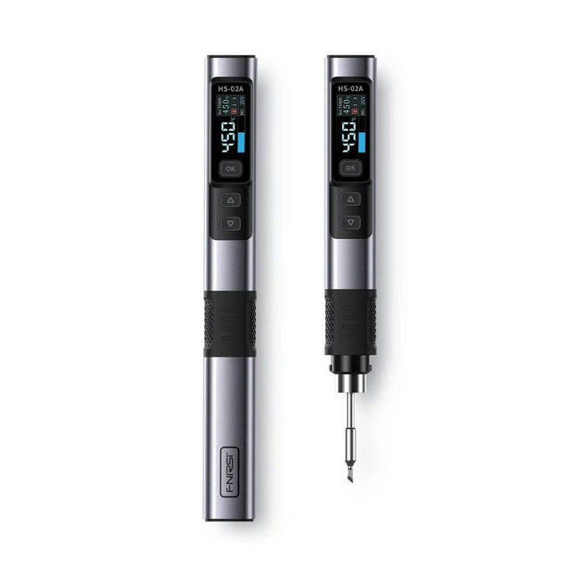
FNIRSI FNIRSI HS-02A Slimme Soldeerbout (incl. 6 soldeertips)
De FNIRSI HS-02A is een verbeterde versie van de HS-01 soldeerbout met een betere grip en een kortere punt voor meer comfort en precisie tijdens gebruik. Het beschikt over een groter 0,96-inch IPS HD-kleurendisplay dat een betere zichtbaarheid van instellingen en status mogelijk maakt. Met een uitgangsvermogen van 100 W warmt de HS-02A snel op en bereikt hij de bedrijfstemperatuur in ongeveer 2 seconden. De temperatuur is instelbaar binnen een bereik van 100-450°C om aan verschillende soldeervereisten te voldoen. Kenmerken Temperatuur: 100-450°C Nauwkeurige aanpassing en controle van de temperatuur Snelle verwarming CNC metalen omhulsel Adaptieve kracht 100 W hoog vermogen Protocollen: PD, QC Specificaties Temperatuurbereik 100-450°C Werkspanning 9-20 V Display 0,96" IPS HD-kleurenscherm Voeding USB-C Snellaadprotocollen PD / QC Vermogen 100 W (max.) Afmetingen 180 x 20 mm Gewicht 61 g Inbegrepen 1x FNRISI HS-02A slimme soldeerbout 6x Soldeerboutpunten (HS02A-KU, HS02A-K, HS02A-JS, HS02A-I, HS02A-C2, HS02A-B) 1x Mini-soldeerboutstandaard 1x Manual Downloads Manual Firmware V1.7
€ 61,95
-
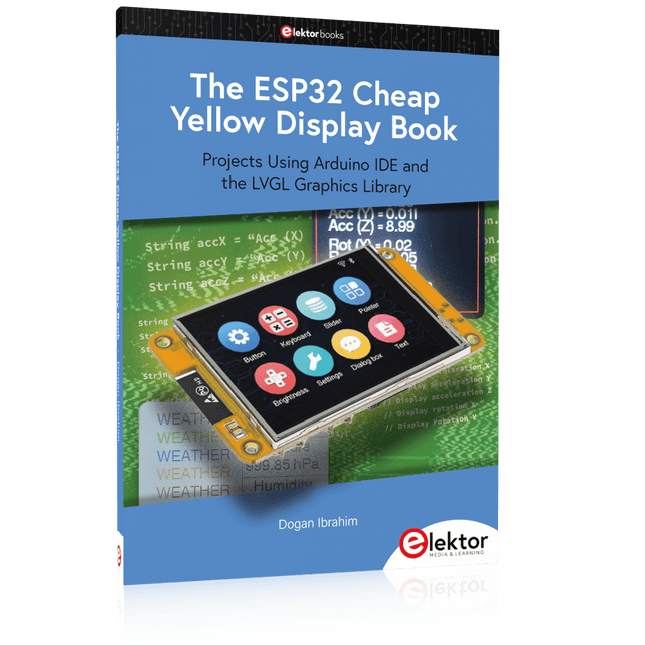
Elektor Publishing The ESP32 Cheap Yellow Display Book
Projects Using Arduino IDE and the LVGL Graphics Library The ESP32 is probably one of the most popular microcontrollers used by many people, including students, hobbyists, and professional engineers. Its low cost, coupled with rich features makes it a popular device to use in many projects. Recently, a board called the ESP32 Cheap Yellow Display (CYD for short) is available from its manufacturers. The board includes a standard ESP32 microcontroller together with a 320x240 pixel TFT display. Additionally, the board provides several connectors for interfaces such as GPIO, serial port (TX/RX), power and Ground. The inclusion of a TFT display is a real advantage as it enables users to design complex graphics-based projects without resorting to an external LCD or graphics displays. The book describes the basic hardware of the ESP32 CYD board and provides details of its on-board connectors. Many basic, simple, and intermediate-level projects are given in the book based on the ESP32 CYD, using the highly popular Arduino IDE 2.0 integrated development environment. The use of both the basic graphics functions and the use of the popular LVGL graphics library are discussed in the book and projects are given that use both types of approaches. All the projects given in the book have been tested and are working. The block diagram, circuit diagram, and the complete program listings and program descriptions of all the projects are given with explanations. Readers can use the LVGL graphics library to design highly popular eye-catching full-color graphics projects using widgets such as buttons, labels, calendars, keypads, keyboards, message boxes, spinboxes, sliders, charts, tables, menus, bars, switches, drop-down lists, animations, and many more widgets.
€ 34,95
Leden: € 31,46
-

Elektor Classics Elektor Archive 1978-2025 (USB Stick) FR
48 années sur clé USB – Année 2025 incluse ! NOUVEAU : Pour les articles à partir de l’année 2000, une option de téléchargement séparée est désormais disponible pour des ressources supplémentaires telles que les plans de PCB, les fichiers Gerber et les logiciels ! Cette clé USB (64 Go, USB 3.0) contient tous les numéros d’Elektor en français des années 1978 à 2025. Elektor propose à ses lecteurs des montages électroniques de conception professionnelle et aisément reproductibles, dans les domaines de l’électronique et de l’informatique appliquées. Il leur apporte également des informations sur l’évolution technologique et les nouveaux produits. Les principaux domaines d’application sont : Alimentation Audio, vidéo & HiFi Auto, moto & vélo Domestique Expérimentation Hautes-fréquences Informations générales Loisirs Mesure Microcontrôleurs & PC Photographie Plus de 10.000 articles d’Elektor sont réunis sur cette clé USB, présentés par ordre de parution (mois/année). Elektor GPT Elektor GPT est un outil basé sur l'IA qui aide les utilisateurs à naviguer dans les archives d'Elektor, vieilles de plusieurs décennies. Grâce à des algorithmes de recherche avancés et au traitement du langage naturel, Elektor GPT trouve rapidement des articles, des projets et d'autres ressources dans les archives. Spécifications Stockage 64 Go Connecteurs 1x USB-A1x USB-C Matériel et logiciel requis Ordinateur avec Adobe Reader version 7 ou sup. Navigateur Internet
€ 199,95€ 79,95
Beste prijs
-

Elektor Publishing The Connected Autonomous Vehicle and its Environment
An Introduction to Real and Reduced-Scale Autonomous Vehicles Want to cut through the hype and get to the core of autonomous and connected vehicles? Then this book is your clear, accessible guide to a complex and fast-moving field. Starting with Intelligent Transport Systems (ITS), it walks you through the essential foundations, including Advanced Driver Assistance Systems (ADAS) – the stepping stones to full autonomy. Explore how self-driving cars mimic human behavior through a loop of perception, analysis, decision, and action. Discover the key functions that make it possible: localization, obstacle detection, driver monitoring, cooperative awareness – and the most challenging of all, trajectory planning, across strategic, tactical, and operational levels. Will vehicles be connected? The debate is on – but the standards are already here. Learn how connectivity, infrastructure, and vehicles can work in synergy through the innovative concept of floating car data (FCD). Dive into real-world implementation: with embedded electronics account-ing for over 30% of a modern vehicle‘s cost, we unpack the architecture, coordination, and tools required to manage the complexity – brought to life with a hands-on case study. To finish, we open the door to the future: building your own 1:10 scale autonomous vehicle. No plug-and-play solutions – just the foundations for a collaborative, creative, and geek-friendly challenge. Let’s drive the future together.
€ 34,95
Leden: € 31,46
-

Andonstar Andonstar ADSM302 5" HDMI Digitale Microscoop
De Andonstar ADSM302 is een veelzijdige digitale microscoop met geïntegreerd 5-inch LCD-scherm en HDMI-uitgang voor haarscherpe beelden in Full HD (1080p). Met een 3-megapixelsensor, een vergroting tot ~560x en twee instelbare ledlampjes maakt hij de kleinste details zichtbaar – ideaal voor het inspecteren van printplaten, soldeerwerkzaamheden, het analyseren van sieraden of insecten. Kenmerken 5" adjustable LCD monitor with adjustable tilt angle High resolution video & photo capture Wide table with comfortable headroom Heavy-weight stable metal stand Tall lifting stand (26 cm) Smooth adjustment wheels for focus and height Buttons on the monitor + remote control AV, USB, HDMI outputs SD card storage <32 GB Specificaties Image sensor 3 Megapixels HD Sensor Video output 1080p Full HD (via HDMI)720p (via PC) Video format Real time play via HDMI w/o recordingMJPEG recording via PC/Mac Software Magnification Up to 560 times (HDMI monitor 22') Photo resolution 12M (see pixel formats in following table) Photo format JPEG Focus range 5 to 22 cm Frame rate Up to 30 f/s under 600 Lux Brightness Video-output interface HDMI/AV Storage microSD card, up to 32 GB PC support Windows XP/7/8/10PC software with measurementMacOS successfully tested under OSX with OBSsee video below Power source 5 V DC Light source 2x LED with the stand Screen size 5 inch (12.7 cm) Stand size 20 x 12 x 26.5 cm Resolutie Captured Photos 4032 x 3024 3648 x 2736 3264 x 2448 2592 x 1944 2048 x 1536 640 x 480 1920 x 1080 1280 x 960 1280 x 720* Videos 1920 x 1080 640 x 480* * (USB with software) Inbegrepen 1x Andonstar ADSM302 digital microscope 1x Metal stand with 2 LEDs 1x USB cable 1x HDMI cable 1x Adapter 1x AI remote 1x Instructions Downloads Manual Software
€ 199,00
-

Raspberry Pi Foundation Le guide officiel du débutant Raspberry Pi (5e édition)
Entièrement mise à jour pour le Raspberry Pi 5 Raspberry Pi 5 est un petit ordinateur intelligent, de construction britannique qui regorge de potentiel. Fabriqué à l'aide d'un processeur économe en énergie, le Raspberry Pi est conçu pour vous aider à apprendre le codage, découvrir comment fonctionne un ordinateur et construire vos propres projets uniques et incroyables. Ce guide est conçu pour vous montrer à quel point il est facile de démarrer. Apprendre à : Configurez votre Raspberry Pi, installez son système d'exploitation, et commencez à utiliser cet ordinateur entièrement fonctionnel. Commencez à coder des projets, avec des guides étape par étape utilisant les langages de programmation Scratch 3, Python et MicroPython. Expérimentez en connectant des composants électroniques, et amusez-vous à créer des projets incroyables. Nouveauté de la 5ème édition : Mise à jour pour les derniers ordinateurs Raspberry Pi : Raspberry Pi 5 et Raspberry Pi Zèro 2 W. Couvre le dernier système d'exploitation Raspberry Pi. Comprend un nouveau chapitre sur le Raspberry Pi Pico ! Téléchargements GitHub
€ 24,95€ 9,95
Beste prijs
-

Elektor Academy Pro Raspberry Pi Pico with Arduino C/C++ (programmeercursus)
Deze complete microcontroller-programmeercursus op basis van de Raspberry Pi Pico bevat een leerboek, een componentenkit, praktische projecten en een uitgebreide online cursus met simulaties. Ideaal om embedded systems stap voor stap te leren programmeren met Arduino via een praktische hands-on aanpak. Een praktische introductie tot embedded systems met de Raspberry Pi Pico Deze cursus is ontworpen voor beginners in embedded systems die op zoek zijn naar een gestructureerde en voorbeeldgerichte start. Een kit met LED’s en weerstanden, schakelaars, sensoren en actuatoren, displays, een breadboard en draden is inbegrepen. Deze worden in de cursus gebruikt om voorbeeldtoepassingen te demonstreren. Er is geen voorkennis van Arduino of embedded ontwikkeling vereist. Elke sectie bevat praktische voorbeelden en mini-projecten om belangrijke concepten te versterken en verdere verkenning te stimuleren. Aan het einde van de cursus kunt u niet alleen de voorbeelden reproduceren, maar ook uitbreiden met uw eigen ideeën en toepassingen. Wat leert u? Microcontroller programmeren in C/C++ met de Raspberry Pi Pico met behulp van de Arduino IDE Werken met digitale I/O, knoppen en encoders uitlezen, LED’s en relais aansturen Analoge ingangen, spanningen en sensoren uitlezen Genereren van analoge uitgangssignalen en PWM Gebruik van seriële communicatie zoals UART, I²C en SPI om displays aan te sturen en digitale sensoren en SD-kaarten uit te lezen Tijdbeheer Werken met interrupts Realtime sensorinput en besturing via knoppen, LED’s en displays Aansturen van actuatoren zoals relais en servomotoren Voor wie is dit? Studenten en zelflerenden die embedded systems willen ontdekken Makers en IoT-enthousiastelingen die hun hardwarevaardigheden willen verbeteren Docenten en trainers die kant-en-klaar lesmateriaal zoeken Wat zit er in de doos? Toegang tot de volledige cursus op het Elektor Academy Pro leerplatform Raspberry Pi Pico microcontrollerboard + USB-kabel Boek: Programming Microcontrollers in C/C++ Using Arduino Downloadbare projectbestanden voor elke module Componentenkit: 2× LED, rood, 5 mm LED, groen, 5 mm 3× weerstand, 470 Ω, 0,25 W LDR Potentiometer, 10 kΩ, lineair Drukknop Rotary encoder module Relaismodule DHT22 temperatuur- en vochtigheidssensor TM1637-compatibel 4-digit 7-segment display MPU-6050 IMU met headers SSD1306-compatibel I²C OLED display Micro SD-kaartadapter met header Buzzer SG90 micro servo ILI9341-compatibel SPI 240×320 TFT display 20× jumper wires Breadboard Alle programmeercursussen (en verschillen in inhoud) Cursus Arduino Raspberry Pi Pico with Arduino C/C++ ESP32 with Arduino C/C++ Raspberry Pi Pico with MicroPython ESP32 with MicroPython Online cursus Access to Arduino Course Access to Pico with Arduino C/C++ Course Access to ESP32 with Arduino C/C++ Course Access to Pico with MicroPython Course Access to ESP32 with MicroPython Course Board Uno R3 Raspberry Pi Pico ESP32 Raspberry Pi Pico ESP32 Boek Programming Microcontrollers in C/C++ Using Arduino Programming Microcontrollers in C/C++ Using Arduino Programming Microcontrollers in C/C++ Using Arduino Programming Microcontrollers in MicroPython Programming Microcontrollers in MicroPython Kit 40-delige componenten-kit 40-delige componenten-kit 40-delige componenten-kit 40-delige componenten-kit 40-delige componenten-kit
€ 69,95
Leden: € 62,96
-

Great Scott Gadgets Acryl behuizing voor HackRF SDR
Deze doorzichtige acryl behuizing is de officiële behuizing voor het HackRF One/Pro board. Hij kan de standaard zwarte plastic behuizing van de HackRF One/Pro vervangen. Montage-instructies Gebruik een plectrum of spudger om de HackRF One/Pro printplaat uit de zwarte plastic behuizing te halen. Steek een lange schroef in elke hoek van het onderste acrylpaneel. Zet elke lange schroef vast met een kort afstandsstuk (5 mm) aan de tegenoverliggende kant van het paneel. Plaats de HackRF One/Pro printplaat (naar boven gericht) bovenop het onderpaneel en steek de uiteinden van de lange schroeven door de bevestigingsgaten in de hoeken van de print. Zet de printplaat vast met een lang afstandsstuk (6 mm) in elke hoek. Plaats het bovenste acrylpaneel op de printplaat en lijn de uitsparingen uit met de extension headers op de print. Zet elke hoek vast met een korte schroef. Opmerking: Niet te strak aandraaien! Na elke stap alleen met de hand aandraaien.
€ 19,95
Leden: € 17,96
-

Elektor Academy Pro Raspberry Pi Pico with MicroPython (programmeercursus)
Deze complete microcontroller-programmeercursus op basis van de Raspberry Pi Pico bevat een leerboek, een componentenkit, praktische projecten en een uitgebreide online cursus met simulaties. Ideaal om embedded systems stap voor stap te leren programmeren in MicroPython via een praktische hands-on aanpak. Een praktische introductie tot embedded systems met de Raspberry Pi Pico Deze cursus is ontworpen voor beginners in embedded systems die op zoek zijn naar een gestructureerde en voorbeeldgerichte start. Een kit met LED’s en weerstanden, schakelaars, sensoren en actuatoren, displays, een breadboard en draden is inbegrepen. Deze worden in de cursus gebruikt om voorbeeldtoepassingen te demonstreren. Er is geen voorkennis van Arduino of embedded ontwikkeling vereist. Elke sectie bevat praktische voorbeelden en mini-projecten om belangrijke concepten te versterken en verdere verkenning te stimuleren. Aan het einde van de cursus kunt u niet alleen de voorbeelden reproduceren, maar ook uitbreiden met uw eigen ideeën en toepassingen. Wat leert u? Microcontrollerprogrammering in MicroPython met de Raspberry Pi Pico met behulp van de Thonny IDE Werken met digitale I/O, knoppen en encoders uitlezen, LED’s en relais aansturen Analoge ingangen, spanningen en sensoren uitlezen Genereren van analoge uitgangssignalen en PWM Gebruik van seriële communicatie zoals UART, I²C en SPI om displays aan te sturen en digitale sensoren en SD-kaarten uit te lezen Tijdbeheer Werken met interrupts Realtime sensorinput en besturing via knoppen, LED’s en displays Aansturen van actuatoren zoals relais en servomotoren Voor wie is dit? Studenten en zelflerenden die embedded systems willen ontdekken Makers en IoT-enthousiastelingen die hun hardwarevaardigheden willen verbeteren Docenten en trainers die kant-en-klaar lesmateriaal zoeken Wat zit er in de doos? Toegang tot de volledige cursus op het Elektor Academy Pro leerplatform Raspberry Pi Pico microcontrollerboard + USB-kabel Boek: Programming Microcontrollers in MicroPython Downloadbare projectbestanden voor elke module Componentenkit: 2× LED, rood, 5 mm LED, groen, 5 mm 3× weerstand, 470 Ω, 0,25 W LDR Potentiometer, 10 kΩ, lineair Drukknop Rotary encoder module Relaismodule DHT22 temperatuur- en vochtigheidssensor TM1637-compatibel 4-digit 7-segment display MPU-6050 IMU met headers SSD1306-compatibel I²C OLED display Micro SD-kaartadapter met header Buzzer SG90 micro servo ILI9341-compatibel SPI 240×320 TFT display 20× jumper wires Breadboard Alle programmeercursussen (en verschillen in inhoud) Cursus Arduino Raspberry Pi Pico with Arduino C/C++ ESP32 with Arduino C/C++ Raspberry Pi Pico with MicroPython ESP32 with MicroPython Online cursus Access to Arduino Course Access to Pico with Arduino C/C++ Course Access to ESP32 with Arduino C/C++ Course Access to Pico with MicroPython Course Access to ESP32 with MicroPython Course Board Uno R3 Raspberry Pi Pico ESP32 Raspberry Pi Pico ESP32 Boek Programming Microcontrollers in C/C++ Using Arduino Programming Microcontrollers in C/C++ Using Arduino Programming Microcontrollers in C/C++ Using Arduino Programming Microcontrollers in MicroPython Programming Microcontrollers in MicroPython Kit 40-delige componenten-kit 40-delige componenten-kit 40-delige componenten-kit 40-delige componenten-kit 40-delige componenten-kit
€ 69,95
Leden: € 62,96
-
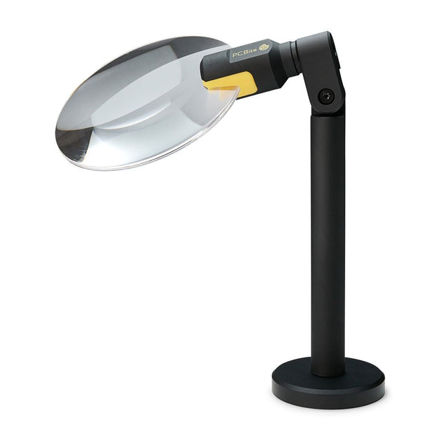
Sensepeek Sensepeek 4020 PCBite 3x vergrootglas
De PCBite loep (premium bouwkwaliteit gemaakt van CNC-bewerkt aluminium) vergroot uw doel en maakt het gemakkelijker om te zien tijdens het solderen, inspectie en metingen. Vooral nuttig bij het plaatsen van PCBite handsfree probes op fijne pitch SMD-componenten tijdens metingen. 3x vergrotende randloze lens voor betere zichtbaarheid van het werkoppervlak en AR coating (anti-reflectie) om reflecties van nabije lichtbronnen te verminderen. Geoptimaliseerd ontwerp, vergroting en brandpunt voor gebruik in combinatie met de PCBite PCB houders en voetplaten die in alle PCBite kits zitten. Kan ook uit de hand worden gebruikt, maar niet standalone zonder een metalen oppervlak als basis. Aan de onderkant van de loepvoet bevindt zich een sterke magneet die perfect in sterkte is uitgebalanceerd. Een lage frictie bodemkap beschermt de magneet en de basisplaat zodat de loep gemakkelijk te verschuiven is bij het verplaatsen of verwijderen van de loep van de basisplaat. Frictie gebaseerde aanpassing van de lens kantel- en draaiposities maakt vervelende en ingewikkelde stelschroeven overbodig.
€ 71,39
-
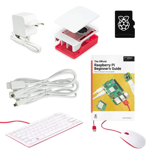
Raspberry Pi Foundation Officiële Raspberry Pi 5 Desktop Kit (EU)
Deze All-in-One Raspberry Pi 5 Desktop Kit bevat alle officiële onderdelen en zorgt ervoor dat je snel en eenvoudig aan de slag kunt met de Raspberry Pi 5. Inbegrepen Officiële 27 W voeding voor Raspberry Pi 5 (EU, wit) Officiële case voor Raspberry Pi 5 (wit/rood) Officieel Raspberry Pi-toetsenbord (US) Officiële Raspberry Pi-muis 2x micro-HDMI naar standaard HDMI-kabel (A/M) 1 m microSD-kaart voorgeïnstalleerd met Raspberry Pi OS (32 GB) The Official Raspberry Pi Beginner's Guide (5th Edition) Niet inbegrepen Raspberry Pi 5
-

OWON OWON XDM1241 True RMS Multimeter
The OWON XDM1241 is a fast, high-precision digital True RMS benchtop multimeter with a high-resolution 3.5-inch LCD and 50,000 counts. Its DC voltage accuracy is up to 0.05% and it can measure up to 65 values per second. Kenmerken 3.5" high-resolution LCD (480x320 pixels) 55000 counts, DC voltage accuracy up to 0.05% Up to 65 readings per second Dual line display supported Trend analysis accessible in chart mode AC True RMS measurements (bandwidth: 20 Hz – 1 kHz) SCPI support: Remote control the multimeter through PC software via USB port Data record function, you can record the measured data into internal memory, and then read and process the recorded data with your computer. Specificaties Measurement Range Resolution Accuracy DC Voltage 50.000 mV 0.001 mV 0.1% +10 500.00 mV 0.01 mV 0.05% +5 5.0000 V 0.0001 V 0.05% +5 50.000 V 0.001 V 0.05% +5 500.00 V 0.01 V 0.1% +5 1000.0 V 0.1 V 0.1% +10 AC Voltage 500 mV~750 V 20 Hz~45 Hz 1% +30 45 Hz~65 Hz 0.5% +30 65 Hz~1 KHz 0.7% +30 DC Current 500 uA 0.01 uA 0.15% +20 5000 uA 0.1 uA 0.15% +10 50 mA 0.001 mA 0.15% +20 500 mA 0.01 mA 0.15% +10 5 A 0.0001 A 0.5% +10 10 A 0.001 A 0.5% +10 AC Current 500 uA~500 mA 20 Hz~1 KHz 0.5% +20 5 A-10 A 1.5% +20 Resistance 500 Ω 0.01 Ω 0.15% +10 5 KΩ 0.0001 KΩ 0.15% +5 50 KΩ 0.001 KΩ 0.15% +5 500 KΩ 0.01 KΩ 0.15% +5 5 MΩ 0.0001 MΩ 0.3% +5 50 MΩ 0.001 MΩ 1% +10 Frequency 10.000 Hz~60 MHz / ±(0.2% +10) Capacitance 50 nF~500 uF / 2.5% +10 5 mF50 mF 5% +10 Diode 3.0000 V 0.0001 V / Continuity 1000 Ω 0.1 Ω Adjustable threshold Temperature K type, PT100 Max Display 55,000 counts Data-logging Function Logging Duration 15ms~9999.999s Logging Length 1,000 points Display 3.5" TFT LCD (480x320 pixels) Power supply Lithium battery via USB-C or 5 V DC input Dimensions 235 x 88 x 65 mm Weight approx. 0.5 kg Inbegrepen 1x OWON XDM1241 Multimeter 2x Test leads 1x USB cable 1x USB to DC cord 1x Manual Downloads Programming Manual PC Software
€ 108,90
-

Elektor Academy Pro Arduino (programmeercursus)
Deze complete microcontroller-programmeercursus op basis van de Arduino Uno bevat een leerboek, een componentenkit, praktische projecten en een uitgebreide online cursus met simulaties. Ideaal om embedded systems stap voor stap te leren programmeren met Arduino via een praktische hands-on aanpak. Een praktische introductie tot embedded systems met de Arduino Uno Deze cursus is ontworpen voor beginners in embedded systems die op zoek zijn naar een gestructureerde en voorbeeldgerichte start. Een kit met LED’s en weerstanden, schakelaars, sensoren en actuatoren, displays, een breadboard en draden is inbegrepen. Deze worden in de cursus gebruikt om voorbeeldtoepassingen te demonstreren. Er is geen voorkennis van Arduino of embedded ontwikkeling vereist. Elke sectie bevat praktische voorbeelden en mini-projecten om belangrijke concepten te versterken en verdere verkenning te stimuleren. Aan het einde van de cursus kunt u niet alleen de voorbeelden reproduceren, maar ook uitbreiden met uw eigen ideeën en toepassingen. Wat leert u? Microcontrollerprogrammering met Arduino met behulp van het Uno R3 board Werken met digitale I/O, knoppen en encoders uitlezen, LED’s en relais aansturen Analoge ingangen, spanningen en sensoren uitlezen Genereren van analoge uitgangssignalen en PWM Gebruik van seriële communicatie zoals UART, I²C en SPI om displays aan te sturen en digitale sensoren en SD-kaarten uit te lezen Tijdbeheer Werken met interrupts Realtime sensorinput en besturing via knoppen, LED’s en displays Aansturen van actuatoren zoals relais en servomotoren Voor wie is dit? Studenten en zelflerenden die embedded systems willen ontdekken Makers en IoT-enthousiastelingen die hun hardwarevaardigheden willen verbeteren Docenten en trainers die kant-en-klaar lesmateriaal zoeken Wat zit er in de doos? Toegang tot de volledige cursus op het Elektor Academy Pro leerplatform Uno R3 microcontrollerboard + USB-kabel Boek: Programming Microcontrollers in C/C++ Using Arduino Downloadbare projectbestanden voor elke module Componentenkit: 2× LED, rood, 5 mm LED, groen, 5 mm 3× weerstand, 470 Ω, 0,25 W LDR Potentiometer, 10 kΩ, lineair Drukknop Rotary encoder module Relaismodule DHT22 temperatuur- en vochtigheidssensor TM1637-compatibel 4-digit 7-segment display MPU-6050 IMU met headers SSD1306-compatibel I²C OLED display Micro SD-kaartadapter met header Buzzer SG90 micro servo ILI9341-compatibel SPI 240×320 TFT display 20× jumper wires Breadboard Alle programmeercursussen (en verschillen in inhoud) Cursus Arduino Raspberry Pi Pico with Arduino C/C++ ESP32 with Arduino C/C++ Raspberry Pi Pico with MicroPython ESP32 with MicroPython Online cursus Access to Arduino Course Access to Pico with Arduino C/C++ Course Access to ESP32 with Arduino C/C++ Course Access to Pico with MicroPython Course Access to ESP32 with MicroPython Course Board Uno R3 Raspberry Pi Pico ESP32 Raspberry Pi Pico ESP32 Boek Programming Microcontrollers in C/C++ Using Arduino Programming Microcontrollers in C/C++ Using Arduino Programming Microcontrollers in C/C++ Using Arduino Programming Microcontrollers in MicroPython Programming Microcontrollers in MicroPython Kit 40-delige componenten-kit 40-delige componenten-kit 40-delige componenten-kit 40-delige componenten-kit 40-delige componenten-kit
€ 69,95
Leden: € 62,96
-

Raspberry Pi Foundation FPC Display Cable for Raspberry Pi 5 (200 mm)
Raspberry Pi 5 provides two four-lane MIPI connectors, each of which can support either a camera or a display. These connectors use the same 22-way, 0.5 mm-pitch “mini” FPC format as the Compute Module Development Kit, and require adapter cables to connect to the 15-way, 1 mm-pitch “standard” format connectors on current Raspbery Pi camera and display products.These mini-to-standard adapter cables for cameras and displays (note that a camera cable should not be used with a display, and vice versa) are available in 200 mm, 300 mm and 500 mm lengths.
-

OWON OWON HDS242 2-ch Oscilloscope (40 MHz) + Multimeter
De HDS242 is een draagbare 2-in-1 multifunctionele tester, die kan worden gebruikt als een 2-kanaals oscilloscoop en multimeter. Hij beschikt over een contrastrijk 3,5-inch kleurendisplay dat geschikt is voor outdoor service, snelle metingen op locatie, voertuigonderhoud, spanningsdetectie, en meer.Kenmerken Oscilloscoop + multimeter 3,5-inch LCD-kleurenscherm met hoge resolutie en hoog contrast – geschikt voor gebruik buitenshuis 18650 lithium accu – kan tot 6 uur continu werken USB Type-C interface - ondersteuning voor powerbank en PC-aansluiting Zelfkalibratie functie SCPI ondersteund – faciliteer secundairy development Specificaties Oscilloscoop Bandbreedte 40 MHz Kanalen 2-kanaals oscilloscoop Sample frequentie 250 MSa/s Acquisition modi Normaal, Piekdetectie Record Lengte 8K Display 3,5-inch LCD Golfvorm refresh rate 10.000 wfrms/s Ingangssignaal DC, AC en Ground Ingangsimpedantie 1 M? ±2%, parallel aan 16pF ±10pF Probe dempingen 1X, 10X, 100X, 1000X, 10000X Max. Ingangsspanning 400 V (DC+AC, PK-PK, 1M? ingangsimpedantie) (10:1 probe demping) Bandbreedte (typical) 20 MHz Horizontale schaal 5ns/div - 1000s/div, in stappen van 1 - 2 - 52ns/div - 1000s/div, in stappen van 1 - 2 - 55ns/div - 1000s/div, in stappen van 1 - 2 - 52ns/div - 1000s/div, in stappen van 1 - 2 - 5 Verticale gevoeligheid 10mV/div - 10V/div Verticale resolutie 8 bits Trigger Type Edge Trigger Modi Auto, Normal, Single Automatische Meting Frequency, Period, Amplitude, Max, Min, Mean, PK-PK Cursor meting ? V, ? T, ?T & ?V tussen cursors Multimeter Max resolutie 20.000 counts Test modi Spanning, Stroom, Weerstand, Capaciteit, Diode en Continuïteitstest Ingangsimpedantie 10 M? Max ingangsspanning AC: 750 V | DC: 1000 V Max ingangsstroom DC: 10 A | AC: 10 A Diode 0-2 V Overig Connectiviteit USB Type-C Afmetingen 198 x 96 x 38 mm (7,68 x 3,74 x 1,5') Gewicht 600 g (zonder accu) Inbegrepen 1x OWON HDS242 Oscilloscoop 1x tasje 1x probe 1x netsnoer 1x probe adjust 1x USB-kabel 1x voedingsadapter 1x set multimeter probe kabels (rode en zwarte) 1x set oscilloscoop probe leads (BNC naar Krokodil) 1x gebruikershandleiding (Engels) Downloads User Manual for HDS200 Series SCPI Protocol for HDS200 Series Quick Guide for HDS200 Series PC Software for OWON HDS200 Series
€ 112,87


