Dat de Raspberry Pi computers ontzettend populair zijn, blijkt uit de 34 miljoen verkochte stuks. Maar dat de Pi computers en technologie tot in de ruimte aan toe reiken, is waarschijnlijk nieuw voor je.
Wat is een Raspberry Pi HAT?
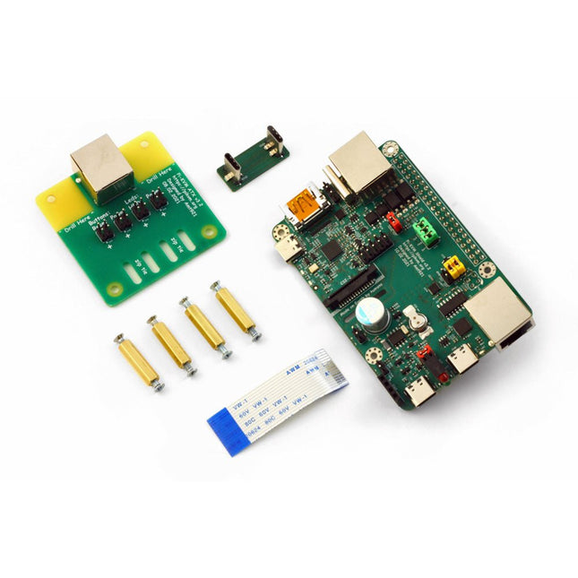
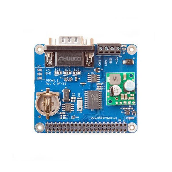
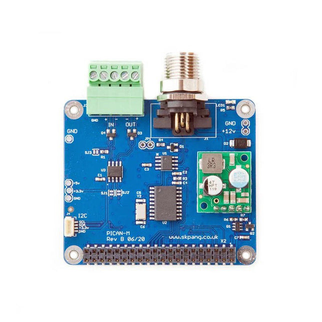
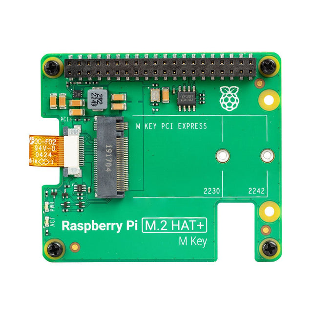
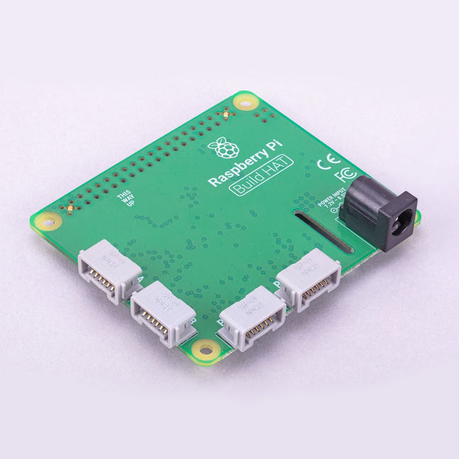
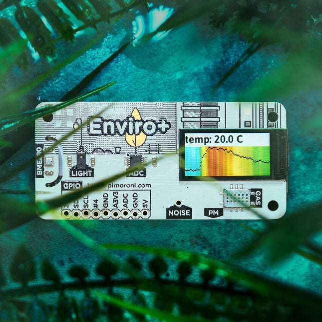
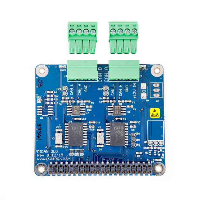
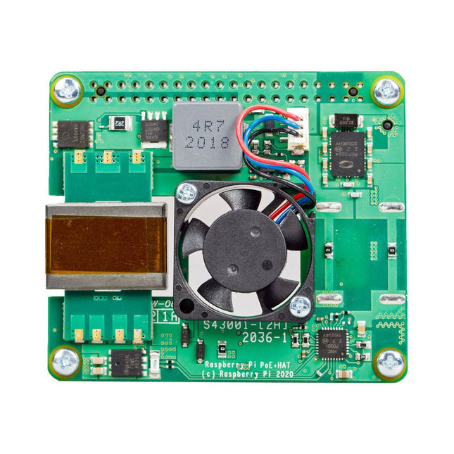
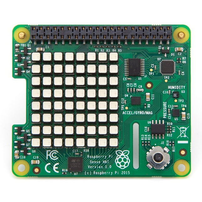
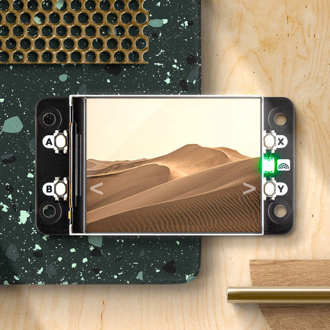
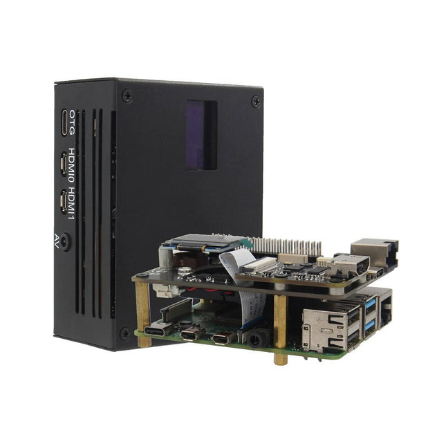
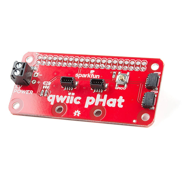
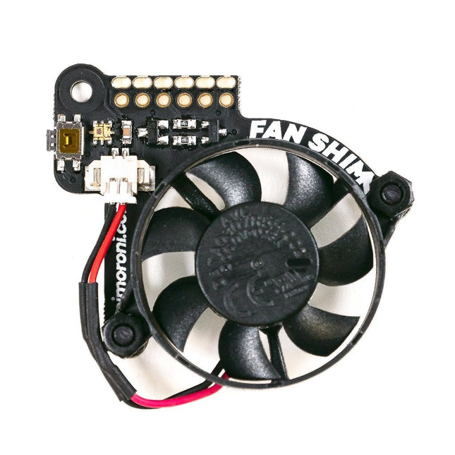
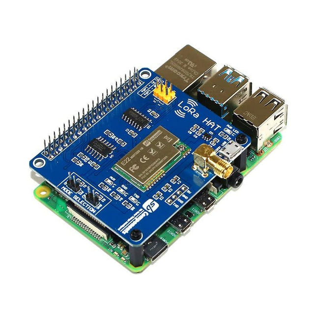
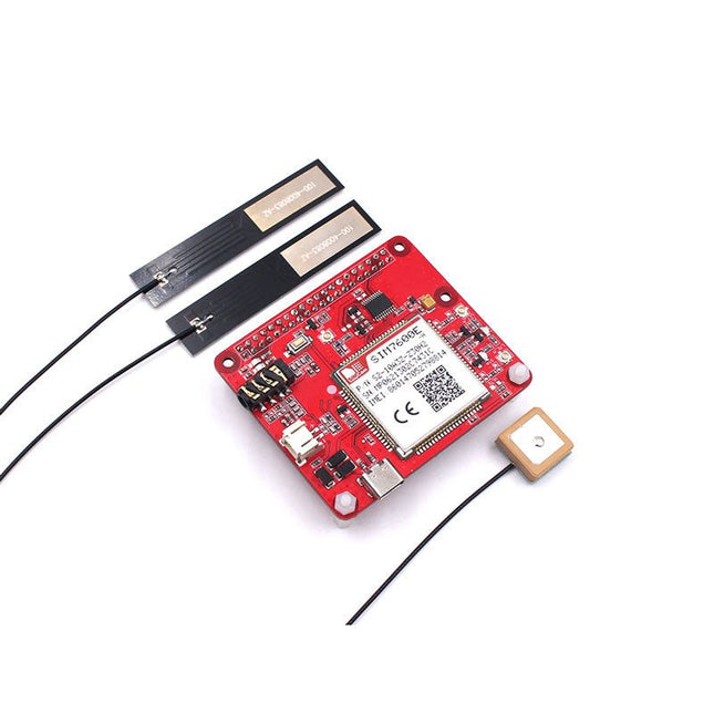
Raspberry Pi HAT’s (Hardware Attached on Top) zijn een add-on module voor op jouw standaard mainbord. Als je meer uit je Raspberry projecten wilt halen, dan zijn HAT’s precies wat je zoekt. Je kunt de HAT’s zo inprikken dankzij de 40-pins GPIO header. Hierdoor breid je niet alleen de hardware uit, maar ook de mogelijkheden die je met die hardware hebt. Wil je meer halen uit de Rasberry Pi, dan zijn HAT’s onmisbaar.
Voor de introductie van de HAT, in 2014, waren er al veel hardwarematige add-ons ontwikkeld voor de minicomputers. Dit was voor Raspberry de reden om zelf een standaard te ontwikkelen dat het makers en programmeurs makkelijker moest maken.
Omdat het aansluiten van externe hardware op de Raspberry Pi een flink aantal handelingen met zich meebracht, is dit met de komst van de HAT verleden tijd. De HAT zorgt er namelijk voor dat de juiste driver automatisch word herkent, ingeladen en aangesloten.
Waar je een Raspberry Pi HAT's voor kunt gebruiken
De mogelijkheden van de technologie en hardware van Raspberry was al groot, maar sinds de introductie van HATS in 2014 zijn deze nog groter geworden. Wie zijn Raspberry mainbord uitbreid met een HAT heeft naast de standaard functionaliteiten van de zijn Pi-model ook
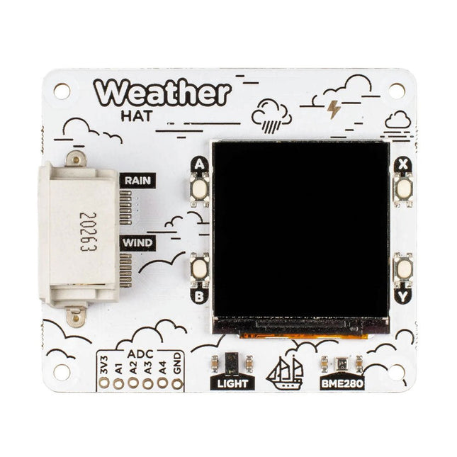
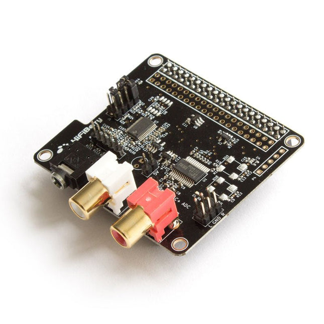
- Meer audio mogelijkheden te krijgen
- Meer display mogelijkheden te krijgen
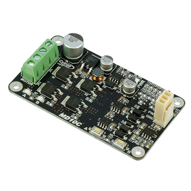
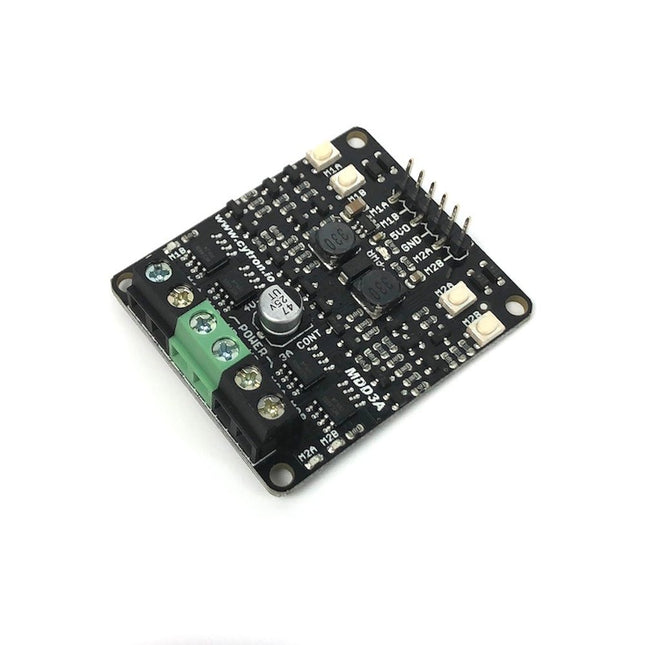
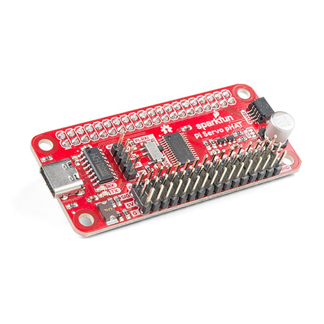
- Of meer Motor & Servo mogelijkheden te krijgen
Met de HATs van Elektor kun je eindeloos combineren en jouw project beter, makkelijker en gebruiksvriendelijker maken.
Het Raspberry Pi assortiment bij Elektor Store
Elektorstore is als goedgekeurde wederverkoper van Raspberry Pi producten de webshop in Nederland om officiële Raspberry producten te kopen. Doordat er geen tussenverkoper tussen de fabriek en onze webshop zit kunnen wij ons assortiment tegen goedkope prijzen aanbieden.