Met de Raspberry Pi heeft u voor slechts een paar tientjes een complete computer in handen, waar op eenvoudige wijze allerlei elektronica aangesloten kan worden. In deze 2e herziene en uitgebreide versie gaan we in op een van de sterke kanten van de Raspberry Pi: de combinatie van programmeren en elektronica.
Na een korte introductie van de Raspberry Pi wordt de benodigde software geïnstalleerd. Op de SD-kaart die u bij dit boek kunt aanschaffen, is die allemaal al aanwezig voor de Raspberry Pi. Aan de (optionele) Windows PC kant gebeurt dit met gratis software die u kunt downloaden.
Daarna volgt een beknopte inleiding in het besturingssysteem Linux en gaan we programmeren in Bash, Python en JavaScript. De nadruk ligt hierbij op Python, maar in alle gevallen houden we het kort. We bespreken net voldoende zodat u de projecten kunt begrijpen en aan uw wensen aanpassen, en gaan dan aan de slag met leuke projecten.
Maar liefst 45 spannende en interessante projecten worden in detail besproken en uitgelegd. Van wisselknipperlicht, aansluiten van een elektromotor, het verwerken en maken van analoge signalen tot lichtmeter en temperatuurregeling. Maar ook gecompliceerdere projecten zoals een motorsnelheidsregeling, webserver met CGI, client-server applicaties en Xwindows programma‘s. U kunt dit boek gebruiken als projecten boek en de projecten nabouwen en in de praktijk inzetten. Door de duidelijke uitleg, schema‘s en foto‘s van de opstellingen op een steekbord wordt het nabouwen een erg leuke bezigheid.
RPiAlle software voor de RPi is voorgeïnstalleerd op een SD-kaart die u bij dit boek kunt aanschaffen. Dat wil zeggen dat alle software en drivers voor SSH, SPI, I²C, GPIO, PWM, muziek, Python Ontwikkelversie, wxPython, IdleX en de seriële verbinding gegarandeerd werken. Tevens staan alle broncodes van de projecten uitdit boek op deze kaart.
Windows-PCIn het gratis download-pakket dat bij dit boek hoort, vindt u de software die in dit boek gebruikt wordt op de Windows-PC handig bij elkaar in een enkel ZIP-bestand. Alle software is gratis. Tevens bevat het pakket een filmpje van de Nutteloze Doos (Useless Machine) van project 13.4.
Software download-pakket:
WinOscillo
Putty
Xming
WinSCP
DiskImager
Notepad2
IdleX
Useless Box film
Elektor GREEN en GOLD leden kunnen deze uitgave hier downloaden.Nog geen lid? Klik hier om een lidmaatschap af te sluiten.
Arduino Portenta Machine Control en Arduino Portenta H7CAN/MQTT-gateway: een demoproject
Uitgepakt: Elektor’s LCR Meter Kitmet David Cuartielles, mede-oprichter van Arduino!
MicroPython betreedt de wereld van Arduino
Connected, maar niet complexneem een duik in de Arduino Cloud
Kennismaking met TinyMLgroot is niet altijd beter
Arduino K-Way:bewust luchtig
Arduino-sketches schrijven is nog beter geworden
Maak kennis met Arduino
Aan de slag met de Portenta X8software veilig beheren met containers
Bouw, uitrol en onderhoud van schaalbare, veilige applicatiesop basis van Arduino Portenta X8 – met de i.MX 8M Mini Applications Processor en EdgeLock SE050 Secure Element van NXP
Hoe ik mijn huis automatiseerdeFabio Violante (CEO Arduino) over zijn oplossingen
Altair 8800-simulatorhardwaresimulatie van een vintage computer
MS-DOS op de Portenta H7antieke software op moderne hardware
Landbouw in zakformaatdigitaal gestuurde kweekbox voor binnenshuis
Met Home Automation de wereld redden?MQTT op de Arduino Nano RP2040 Connect
Arduino Pro voor professionals
Slimme ovens – de ovens van de toekomst
Tagvance maakt bouwlocaties veiliger met Arduino
Santagostino krijgt genoeg luchtmet bewaking op afstand en gebruik van AI bij voorspellend onderhoud
Beveiliging neemt een hoge vlucht met RIoT Secure’s MKR-gebaseerde oplossing
Open-Source brengt de wereld een nieuwe generatie watermanagement
Sensoontbossing detecteren met geluidsanalyse
De Mozzi Arduino-library voor geluidssynthesegedachten van Tim Barrass
De nieuwe Portenta X8 (met Linux!) en Max Carrier herdefiniëren het haalbare
Hoe de Arduino studenten aan vaardigheden voor de toekomst helpt
Must-haves voor je elektronica-werkplek
Het belang van robotica in het onderwijs
Betrouwbaar IoT op basis van LoRa
Aan de slag met de Portenta Machine Control
8bit-gaming met Arduboy
Spaar water op de paardenrenbaanmeet continu de bodemvochtigheid en temperatuurniveau via IoT
Het panettone-projectzuurdesemstarter onder controle
Met steun van deze Arduino-resellers
Space Invaders met Arduino
Kunst met Arduinoinspirerende inzichten van kunstenaars en ontwerpers
Aan de slag met nieuwe Arduino-hardware!
De toekomst van Arduino
Elektor GREEN en GOLD leden kunnen deze uitgave hier downloaden.
Nog geen lid? Klik hier om een lidmaatschap af te sluiten.
Het AlertAlfred AI-beveiligingssysteemmet Raspberry Pi 5 en Hailo 8L-module
AI in elektronica-ontwikkelingeen update na slechts één jaar
AI-algoritmen – een inleidingprompt: welke algoritmen implementeren AI-tools?
Single-board computers voor AI-projectenachtergrond en overzicht
Van sensordata naar machine learning-modelgebarendetectie met een versnellingsmeter en Edge Impulse
Bouw uw eigen lekkend integreer-en-vuur neuronkunstmatige intelligentie zonder software
Elektronica ontwerpen met ChatGPTdoet GPT-4o het beter?
Breng AI naar de edgemet ESP32-P4
Spraakfuncties verkennen met een Raspberry Pi Zerooverklokken geeft recht van spreken
De groeiende rol van Edge-AIeen trend die de toekomst vormgeeft
De kracht van Edge-AI ontsluiteneen gesprek met François de Rochebouët van STMicroelectronics
Een VHDL-klok gemaakt met ChatGPThoe AI de manier waarop we leren transformeert
De werkelijke impact van AISayash Kapoor over ‘Haarlemmer AI-olie’ en meer
Het laatste nieuws van BeagleBoardBeagleY-AI, BeagleV-Fire, BeagleMod, BeaglePlay en BeagleConnect Freedom
Muggen detecterenmet open datasets en Arduino Nicla Vision
AI nu en morgen:gedachten van Espressif, Arduino en SparkFun
Tijdlijn kunstmatige intelligentie
BeagleY-AIde nieuwste SBC voor AI-toepassingen
AI in beeldgedachten uit de Elektor-community
Machine vision met OpenMVmaak een frisdrankblik-detector
Een gesprek met het digitale breinChatGPT versus Gemini
“Skilling Me Softly with This Bot?”mislukt de AI-revolutie op elektronisch gebied door een gebrek aan sociale precisie?
Bouw uw eigen RISC-V-controllerEerste stappen met de NEORV32 RISC-V softcore voor goedkope FPGA’s
Het gebruik van Arduino’s seriële plotterGrafieken plotten met Arduino is gemakkelijk
CLUE van AdafruitEen slimme oplossing voor IoT-projecten
Bufferboard voor de Raspberry Pi 400Bescherm uw I/O’s
Raspberry Pi RP2040-boards in overvloed
Een handboek voor DHZ elektronische beveiliging en spionageSRAM – gebakken of diepgevroren
Onderdelen identificerenTips & trucs, vakkunstigheden en andere nuttige informatie
DHZ aanraakloze lichtschakelaar
Alle begin......gaat compenseren en transformeren
Nieuwe embedded-ontwikkelingenRust en het up-to-date houden van IoT-implementaties
Infographics
Hoe de industrie- en automobielsector zullen profiteren van 5G
Relais met bewegende spoelVreemde onderdelen
Oost West Lab BestAlles draait om de bank...
Kennismaking met neuronen in neurale netwerkenDeel 4: embedded neuronen
Magnetische levitatie “the very easy way”De derde en meest compacte versie
PLC-programmering met de Raspberry Pi en het OpenPLC-projectVisualisatie van PLC-programma’s met AdvancedHMI
Uit het leven gegrepenInpakken en wegwezen
Onder de radarMicrocontrollers die u zou moeten kennen
Draadloos monitoren en debuggenvoor Arduino, ESP32 en co.
Draagbare temperatuur- en vochtigheidsmetermet gebruiksklare modules
Lithium-accupacks reparerenSpaart geld + geeft meer kracht!
GUI's maken met PythonMeme-Generator
De drie grote vraagtekensWaarom wat wie
Hexadoku
ZELFBOUW LIPO-SUPERCHARGER KITvan prototype tot productie
ELEKTOR @ 60gedachten bij zestig jaar elektronica
SIGLENT SDM3045X TAFELMULTIMETER
DC-STROOMKLEMHall-sensor + ferrietkern + Arduino
SOLDEERSTATION 2021makkelijk om te bouwen!
KENNISMAKING MET DE PARALLAX PROPELLER 2 (DEEL 2)de ontwikkelomgeving en de code
WIFI VOOR DE LORA SWITCHgeïntegreerd in Home Assistant met ESPHome
GEEN ANGST VOOR DE CELLULAIRE MODULE!
HOUD DE TIJD BIJ MET ESP32 EN TOGGLwerken met de M5Stack
KENNISMAKING MET HET RASPBERRY PI PICO-BOARD EN DE RP2040
MICROPYTHON VOOR MICROCONTROLLERStechnieken voor kleine displays
12–200 V DC/DC-CONVERTERvoor buizenversterkers
WARMTEZOEKERde Seek Shot Pro warmtebeeldcamera
OBJECTGEORIËNTEERD PROGRAMMERENeen korte inleiding met C++
OOST WEST LAB BEST...waar Kurt Diedrich synthesizers bouwt
JAVA OP DE RASPBERRY PIdeel 1: GPIO’s
DIP-SCHAKELAARSvreemde onderdelen
INTERACTIEFcorrecties & updates || brieven van lezers
WIENS PRODUCT IS HET EIGENLIJK?recht-op-reparatie beweging laat van zich horen
UIT HET LEVEN GEGREPENhet grote blunderboek
MICRO-PROFESSORassembleertaal leren op een Z80
ALLE BEGIN......hoeft niet zo moeilijk te zijn – zelfs als het om condensatoren gaat
HEXADOKUThe Original Elektorized Sudoku
Valentine's Hearts, 28 blinking LEDs, romantic LED lighting Valentine's Hearts – 28 blinking LEDs for a romantic atmosphere. The perfect Valentine's gift to express your love. Battery-powered and portable, ideal for Valentine's Day.
Downloads
Manual
The Whadda E12 is a high-quality carbon film resistor set comprising 610 pieces, with 10 pieces for each of the 61 standard E12 series values ranging from 10 Ω to 1 MΩ. Each resistor has a power rating of 0.25 W, a tolerance of 5%, and can operate within a temperature range of -55°C to 155°C. The maximum operating voltage is 250 V.
These resistors are suitable for applications in TVs, audio and video equipment, telephone receivers, communication systems, instrumentation, and home appliances.
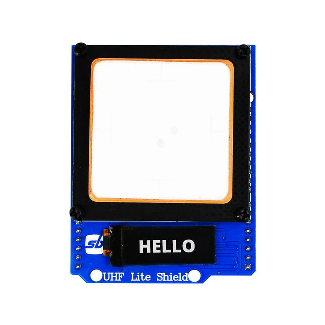
Designed with cutting-edge technology, this shield brings the power of Ultra High Frequency (UHF) RFID to your fingertips.
With the Ardi UHF Shield, you can effortlessly read up to an impressive 50 tags per second, allowing for fast and efficient data collection. The shield features an onboard UHF antenna, ensuring reliable and accurate tag detection even in challenging environments.
Equipped with a high-performance 0.91" OLED display, the Ardi UHF Shield provides clear and concise visual feedback, making it easy to monitor and interact with the RFID readings. Whether you're tracking inventory, managing access control, or implementing a smart attendance system, this shield has you covered.
With a remarkable 1-meter reading distance, the Ardi UHF Shield offers an extended range for capturing RFID data. Say goodbye to the limitations of proximity-based RFID systems and embrace the flexibility and convenience of a wider reading range.
The shield provides read-write capabilities, allowing you to not only retrieve information from RFID tags but also update or modify data as needed. This versatility opens up a world of possibilities for advanced applications and custom solutions.
Features
Onboard High-performance UHF RFID reader module
24 hours x 365 days’ work normally
0.91” OLED display for visual interaction with shield
Multi-tone Buzzer onboard for Audio alerts
Shield compatible with both 3.3 V and 5 V MCU
Mounts directly onto ArdiPi, Ardi32 or other Arduino compatible boards
Specifications
OLED resolution 128x32 pixels
I²C Interface for OLED
UHF Frequency Range (EU/UK): 865.1-867.9 MHz
UHF Module Type: Read/Write
Protocols Supported: EPCglobal UHF Class 1 Gen 2 / ISO 18000-6C
Reading Distance: 1 meters
Can identify over 50 tags simultaneously
Communication interface: TTL UART Interface for UHF
Communication baud rate: 115200 bps (default and recommend) – 38400 bps
Operation current: 180 mA @ 3.5 V (26 dBm Output, 25°C), 110 mA @ 3.5 V (18 dBm Output, 25°C)
Working humidity <95% (+25°C)
Heat-dissipating method Air cooling(no need out install cooling fin?
Tags storage capacity: 200 pcs tags @ 96 bit EPC
Output power: 18-26 dBm
Output power accuracy: +/-1 dB
Tags RSSI support
With 20+ Practical Projects in Logic and Circuit Design
This book is a practical guide to digital electronics, covering the essential components of modern digital systems: number systems, logic gates, Boolean algebra, combinational and sequential logic, and more.
Through more than 20 structured projects, you’ll design and build digital systems using real-world components such as logic gates, multiplexers, decoders, flip-flops, counters, and shift registers. The projects range from basic LED logic circuits to digital locks, display systems, traffic light controllers, and timing-based designs.
Selected projects introduce the use of tools such as CircuitVerse for circuit simulation, while several designs make use of 74HC-series logic devices, commonly used in digital hardware prototyping.
Inside, you’ll find:
Clear coverage of number systems and binary arithmetic
Logic gate fundamentals and universal gate implementations
Step-by-step projects using flip-flops, counters, and registers
Real-world design with 74HC-series logic chips
Techniques for designing combinational and sequential systems
This book takes a design-first, application-driven approach to digital electronics—built around working circuits, tested logic, and hands-on experimentation.
Two reasons can be identified for the immense success of the Arduino platform. First, the cheap, ready to go processor board greatly simplifies the introduction to hardware. The second success factor is the free and open-source programming suite that does not require an installation procedure.
Simple entry-level examples ensure rapid successes. Complex selection procedures for parameters like the microprocessor version or interface settings are not required. The first sample programs can be uploaded to the Arduino board, and tested, in a matter of minutes.
The Arduino user is supported by an array of software libraries. However, the daily increasing volume of libraries poses initial problems to the newcomer, and the way ahead may be uncertain after a few entry-level examples. In many cases, detailed descriptions are missing, and poorly described projects tend to confuse rather than elucidate. Clear guidance and a single motto are missing, usually owing to the projects having been created by several different persons—all with different aims in mind.
This book represents a different approach. All projects are presented in a systematical manner, guiding into various theme areas. In the coverage of must-know theory great attention is given to practical directions users can absorb, including essential programming techniques like A/D conversion, timers and interrupts—all contained in the hands-on projects. In this way readers of the book create running lights, a wakeup light, fully functional voltmeters, precision digital thermometers, clocks of many varieties, reaction speed meters, or mouse controlled robotic arms. While actively working on these projects the reader gets to truly comprehend and master the basics of the underlying controller technology.
Elektor GREEN en GOLD leden kunnen deze uitgave hier downloaden.
Nog geen lid? Klik hier om een lidmaatschap af te sluiten.
De open-source processorarchitectuur RISC-V16 boards en MCU's die je moet kennen
Een FPGA-gebaseerde audiospeler met equalizer (1)Digitaal audio mixen met een Arduino MKR Vidor 4000
Laserkop voor pico-gebaseerde zandklokTekenen met licht
Doe mee aan de STM32 Edge AI Contest
Een multi-sensor plantenmonitor-systeemdraadloze meting van watertoevoer en lichtomstandigheden
Maixduino AI-gestuurde automatische portiergezichtsdetectie met een camera
Embedded Electronics 2024AI gaat de industrie opnieuw vormgeven
Lading-gebaseerde in-Memory computing bij EnCharge AI
AI-Inferentie met 10 Keer Lager Energieverbruik en 20 Keer Lagere Kosten
Click board ondersteunt het ontwikkelen en trainen van ML-modellen voor trillingsanalyse
De Elektor Mini-WheelieEen kit voor een zelfbalancerende robot
MCU, ik zie jeMCUViewer: open-source multiplatform debugging-tool
USB 2.0-isolatorelektrisch geïsoleerde USB-aansluiting
Voorkomen is betervoorspellend onderhoud in de praktijk
SPoE – Elektromagnetische compatibiliteitSingle pair met Power-over-Ethernet door de ogen van EMC
Retro techEen nieuwe wereld met kleurentelevisie
ECG-monitorimplementatie met Hexabitz-modules en een STM32CubeMonitor
De strijd om AI aan de edge
Met HaLow Wi-Fi is een record afstand bereikt van 16 km op 900 MHz
Eerste CHERI RISC-V Embedded Chip en Early Access programma
Derde generatie bosbranddetectie maakt gebruik van satellietverbindingen
Uit het leven gegrepenkeuzestress
Alle begin......filtert verder en regelt tonen
Quasi-analoog uurwerkwedergeboorte van een Elektor-klassieker
Een modulaire sensortesterSensor-evaluatieboard met ESP32-S3
2025: Een AI-OdysseeDe opkomst van foundation modellen en hun rol in het democratiseren van AI
Raspberry Pi standalone MIDI-synthesizer (1)voorbereiding van een platform voor enkele edge-AI-experimenten
Err-lectronicsCorrecties, updates en brieven van lezers
Universele AI RISC-V processor doet ze allemaal - CPU, GPU, DSP, FPGA
Interview met de CEO: Ventiva's dunne en coole technologie
Dual-core programmeren met een Raspberry Pi Picoduik in de wereld van parallel programmeren
This book is intended as a highly-practical guide for Hobbyists, Engineers and Scientists wishing to build measurement and control systems to be controlled by a local or remote Personal Computer running the Linux operating system. Both hardware and software aspects of designing typical embedded systems are covered in detail with schematics, code listings and full descriptions. Numerous examples have been designed to show clearly how straightforward it can be to create the interfaces between digital and analog electronics, with programming techniques for creating control software for both local and remote systems. Hardware developers will appreciate the variety of circuits, including a novel, low cost modulated wireless link and will discover how using Matlab® overcomes the need for specialist programming skills.
Software developers will appreciate how a better understanding of circuits plus the freedom offered by Linux to directly control at the register level enables them to optimize related programs. There is no need to buy special equipment or expensive software tools in order to create embedded projects covered in this book. You can build such quality systems quickly using popular low-cost electronic components and free distributed or low-cost software tools. Some knowledge of basic electronics plus the very basics of C programming only is required.
Many projects in this book are developed using Matlab® being a very popular worldwide computational tool for research in engineering and science. The book provides a detailed description of how to combine the power of Matlab® with practical electronics.
With an emphasis on learning by doing, readers are encouraged by examples to program with ease; the book provides clear guidelines as to the appropriate programming techniques “on the fly”. Complete and well-documented source code is provided for all projects.
If you want to learn how to quickly build Linux-based applications able to collect, process and display data on a PC from various analog and digital sensors, how to control circuitry attached to a computer, then even how to pass data via a network or control your embedded system wirelessly and more – then this is the book for you!
Features of this Book
Use the power, flexibility and control offered only by a Linux operating system on a PC.
Use a free, distributed downloadable GNU C compiler Use (optional) a low-cost Student Version of Matlab®.
Use low-cost electronic sub-assemblies for projects.
Improve your skills in electronics, programming, networking and wireless design.
A full chapter is dedicated to controlling your sound card for audio input and output purposes.
Program sound using OSS and ALSA.
Learn how to combine electronic circuits, software, networks and wireless technologies in the complete embedded system.
The Raspberry Pi is a $35 credit-card sized computer with many applications, such as in desktop computing, audio and video playback, and as a controller in many industrial, commercial and domestic applications.
This book is about the Raspberry Pi computer and its use in control applications. The book explains in simple terms, with examples, how to configure the RPi, how to install and use the Linux operating system, how to write programs using the Python programming language and how to develop hardware based projects.
The book starts with an introduction to the Raspberry Pi computer and covers the topics of purchasing all the necessary equipment and installing/using the Linux operating system in command mode. Use of the user-friendly graphical desktop operating environment is explained using example applications. The RPi network interface is explained in simple steps and demonstrates how the computer can be accessed remotely from a desktop or a laptop computer.
The remaining parts of the book cover the Python programming language, hardware development tools, hardware interface details, and RPi based hardware projects. All the 23 projects given in the book have been tested and are working.
The following headings are given for each project:
Project title
Project description
Project block diagram
Project circuit diagram
Project program description using the Program Description Language (PDL)
Complete program listing
Description of the program
The book is ideal for self-study, and is intended for electronic/electrical engineering students, practising engineers, research students, and hobbyists.
De werking van veruit de meeste moderne elektronische apparaten is niet slechts op één enkel principe gebaseerd. Vaak staat een of andere computer (doorgaans een microcontroller) centraal. Uit deze fundamentele opzet – een computer die is ingebed in een bepaalde toepassingsschakeling – is de algemene benaming Embedded Systems voortgekomen. De meeste van deze systemen moeten vanuit het niets worden ontwikkeld, en daarbij komt het op elk detail aan. Vindingrijkheid en veelzijdigheid zijn dan een vereiste. De problemen die opgelost moeten worden, vormen niet zelden een ware uitdaging en betreffen niet alleen de analoge en digitale elektronica maar ook de systeemarchitectuur, programmering en programma-organisatie. De delen van deze reeks zijn geschreven voor iedereen – leerling, student of beginnend elektronicus – die zich terdege wil bekwamen in de professionele hardware- en systeemontwikkeling. En ze richten zich tot de allround-elektronicus die geen tijd heeft om specialist op een van de vele deelgebieden te worden maar die weet dat hij met standaard huis-, tuin- en keukenoplossingen niet ver komt. Ze bieden wat studenten en professionele elektronici nodig hebben: een opfrissing en verdieping van de basiskennis, een bron van inspiratie en een schat aan details en spitsvondigheden. Dit deel behandelt de passieve componenten: vaste weerstanden • instelbare weerstanden • NTC- en PTC-weerstanden • spanningsafhankelijke weerstanden • condensatoren • spoelen • transformatoren • contactelementen Andere delen in deze reeks: Digitale technieken • Hard- en software • Signaalwegen • Basisschakelingen
In Elektronica Kunst & Kunde worden alle onderwerpen behandeld die ook in standaard elektronica-leerboeken aan de orde komen, plus een groot aantal belangrijke maar vaak veronachtzaamde zaken.
In dit tweede deel aandacht voor onder meer de volgende onderwerpen:
phase-locked loop-schakelingen, opto-elektronica, busschakelingen, capacitieve belasting, bekabeling, interfacing
timing, naaldpulsen, klokvertraging, monostabiele multivibratoren
de IBM-PC en de Intel-fanilie, RS232-kabels, seriële poorten, ASCII, modems, SCSI, IPI, GPIB, parallele poorten, local-area-networks
de 68000-microprocessorfamilie, perifere LSI-chips, geheugen, programmeerbare instrumenten
prototypering, het ontwerpen van printplaten, wire-wrap-technieken, CAD/CAM technieken, de bouw van schakelingen
HF-modules, vereenvoudigd ontwerp van HF-versterkers en high-speed schakelaars
batterijen, accu's en zonnecellen; micropower-regelaars, -opamps en -microprocessoren
methoden om de bandbreedte te beperken, middeling van signalen, lock-in versterkers, pulshoogte-analyse, 'multichannel-scaling'
Eerste stappen met een ESP32-C3 en het IoTWiFi-knop en -relais
IoT Cloud à la Arduino
Arduino-shield met dubbele Geiger-Müller buisuiterst gevoelige en zeer zuinige stralingssensor
CO2-wachterluchtkwaliteit bewaken – doe het zelf!
MonkMakes Air Quality Kit voor de Raspberry Pimeet temperatuur en eCO2
Alle begin......verwelkomt de diode
Tips & trucs voor het testen van componentenzonder kostbare apparatuur
Reduceer het stroomverbruik van uw mollenverjagerATtiny13 in plaats van 555
Lichtschakelaar DeLuxuiterst nauwkeurig lichtgestuurd schakelen
Uitdagingen bij het op de markt brengen van IoT-oplossingenzorgen over veiligheid, schaalbaarheid en de concurrentie
Elektor Infographics
Toch beter bedraadTips voor het ontwikkelen van een 1 Gbit/s interface in de industriële omgeving
Edge Impulse FOMOreal-time objectdetectie voor MCU’s
Lopende-golfbuisVreemde onderdelen, de serie
Smalband-Internet of Thingsstandaarden, dekking, overeenkomsten en modules
Dragino LPS8 indoor-gatewayLoRaWAN-gateway snel geïnstalleerd
Ontdek ATtiny-microcontrollers met behulp van C en assemblervoorbeeldhoofdstuk: ATtiny I/O-poorten
Project 2.0correcties, updates en brieven van lezers
LoRa GPS-tracker updateontvang en toon de locatie met een Raspberry Pi
Schakelingen simuleren met TINA Design Suite & TINACloudvoorbeeldhoofdstuk: sinusoscillatoren
Uit het leven gegrepenlopendebandwerk
Het WinUI grafische framework voor Windows-appseen kleine demo-applicatie
GUI's maken met Python's Werelds slechtste GUI
Off-grid PV-systeemelektrische energie onafhankelijk van het net
De 10-jaar-smartphonestel uw verwachtingen bij
Hexadoku
Deze ultrasone afstandssensor (ME007-ULA V1) biedt hoge prestaties met een robuuste, waterdichte sonde. De sensor werkt volgens het principe van ultrasone echobereik en bepaalt de afstand tot een doel door de tijd te meten die is verstreken tussen het verzenden van een puls en het ontvangen van de echo. Dankzij het contactloze ontwerp kan hij een breed scala aan materialen detecteren, waaronder transparante of non-ferro voorwerpen, metalen, niet-metalen, vloeistoffen, vaste stoffen en poeders.
Specificaties
Afstand detecteren
27~800 cm
Uitvoerinterface
RS232, spanning analoog
Bedrijfsspanning
5-12 V
Gemiddelde stroom
<10 mA
Bedrijfstemperatuur
−15~60°C
Afmetingen
60 x 43 x 31 mm
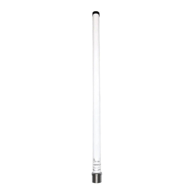
Deze buitenantenne van glasvezel is geoptimaliseerd voor het ontvangen van signalen in de 868 MHz ISM-band en ondersteunt technologieën zoals Sigfox, LoRa, Mesh Networks en Helium. De antenne bestaat uit een halvegolfdipool met een versterking van 4,4 dBi, ingekapseld in een glasvezelradome met een aluminium montagebasis.
Specificaties
Frequentie
868-870 MHz
Antennetype
Dipool 1/2 golf
Connector
N vrouwelijk
Installatietype
Mastdiameter 35-60 mm (montagebeugel meegeleverd)
Winst
4,4 dBi
SWR
≤1,5
Type polarisatie
Verticaal
Maximaal vermogen
10 W
Impedantie
50 Ohm
Afmetingen
52,5 cm
Buisdiameter
26 mm
Basisantenne
32 mm
Bedrijfstemperatuur
−30°C tot +60°C
Inbegrepen
ISM-bandantenne (868 MHz)
Mastbeugel (voor installatie op een mast met een diameter van 35 tot 60 mm)
4 LEDs and 4 push buttons ensure hours of fun. Repeat the combination, harder and harder, faster and faster. The microprocessor-controlled game has 4 different difficulty levels and low consumption. The sound and/or LED indication are adjustable. To save the three 1.5 V AA batteries (not included), the kit automatically switches itself off when not in use.
Downloads
Manual
Waveshare CoreEP4CE10 is an FPGA core board that features an EP4CE10F17C8N device onboard supporting further expansion.
Features
Onboard Serial Configuration Device EPCS16SI8N
Integrated FPGA basic circuit, such as clock circuit
Onboard nCONFIG button, RESET button, 4x LEDs
All the I/O ports are accessible on the pin headers
Onboard JTAG debugging/programming interface
2.00 mm header pitch design, suitable for being plugged-in your application system
Downloads
Wiki
Waveshare DVK600 is an FPGA CPLD mother board that features expansion connectors for connecting FPGA CPLD core board and accessory boards. DVK600 provides an easy way to set up FPGA CPLD development system.
Features
FPGA CPLD core board connector: for easily connecting core boards which integrate an FPGA CPLD chip onboard
8I/Os_1 interface, for connecting accessory boards/modules
8I/Os_2 interface, for connecting accessory boards/modules
16I/Os_1 interface, for connecting accessory boards/modules
16I/Os_2 interface, for connecting accessory boards/modules
32I/Os_1 interface, for connecting accessory boards/modules
32I/Os_2 interface, for connecting accessory boards/modules
32I/Os_3 interface, for connecting accessory boards/modules
SDRAM interface
for connecting SDRAM accessory board
also works as FPGA CPLD pins expansion connectors
LCD interface, for connecting LCD22, LCD12864, LCD1602
ONE-WIRE interface: easily connects to ONE-WIRE devices (TO-92 package), such as temperature sensor (DS18B20), electronic registration number (DS2401), etc.
5 V DC jack
Joystick: five positions
Buzzer
Potentiometer: for LCD22 backlight adjustment, or LCD12864, LCD1602 contrast adjustment
Power switch
Buzzer jumper
ONE-WIRE jumper
Joystick jumper
Downloads
Schematics
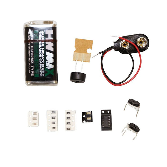
The Punk Console circuit is an advanced tutorial to get you familiar with the V-One Drill attachment. Learn how to create a double sided board and turn the knobs to create music! The kit contains: 2x Green LEDs 8x 1k Resistors 3x 0.01uF Capacitor 2x 500K Trimpots 1x 556 Timer 1x Piezo Buzzer 1x 9 V Battery 1x 9 V Battery Connector Rivets and a V-One Drill are required.
De MLX90640 SparkFun IR Array Breakout heeft een 32×24 array van thermopile sensoren die, in essentie, een lage resolutie warmtebeeld camera genereren. Met deze breakout kan je oppervlaktetemperaturen vanop een behoorlijke afstand waarnemen met een nauwkeurigheid van ±1.5 °C (in het beste geval). Dit bord communiceert via I²C met behulp van het door Sparkfun ontwikkelde Qwiic systeem, wat de bediening van de breakout vergemakkelijkt. Er zijn echter nog steeds 0,1'-spaced pinnen voor het geval u de voorkeur geeft aan het gebruik van een breadboard. Het SparkFun Qwiic connect systeem is een ecosysteem van I²C sensoren, actuatoren, shields en kabels die het prototypen sneller maken en u helpen fouten te voorkomen. Alle Qwiic-compatibele borden gebruiken een gemeenschappelijke 1 mm pitch, 4-pins JST-connector. Dit vermindert de benodigde PCB ruimte, en gepolariseerde aansluitingen helpen u alles correct aan te sluiten. Deze specifieke IR Array Breakout biedt een gezichtsveld van 110°×75° met een temperatuurmeetbereik van -40 °C ~ 300 °C. De MLX90640 IR Array heeft pull up weerstanden op de I²C bus; beide kunnen worden verwijderd door de sporen op de overeenkomstige jumpers aan de achterkant van de printplaat door te knippen. Let erop dat de MLX90640 complexe berekeningen vereist van het host platform, dus een gewone Arduino Uno (of gelijkwaardig) heeft niet genoeg RAM of flash om de complexe berekeningen uit te voeren die nodig zijn om de ruwe pixel data om te zetten in temperatuur data. U heeft een microcontroller nodig met 20.000 bytes of meer RAM.