Bestsellers
-

Elektor Labs Elektor 'Woordrijke' LED-kerstboom
Meertalige DIY-kit (incl. 27 RGB-LED's + Raspberry Pi Pico) Geef uw kerstperiode een vleugje techniek met de "woordrijke" LED-kerstboom van Elektor. De prachtig ontworpen 3D-kerstboom combineert elf printplaten, een Raspberry Pi Pico en 27 adresseerbare RGB-LED's om feestelijke boodschappen in zeven talen te laten oplichten: Deens, Nederlands, Engels, Frans, Duits, Italiaans en Spaans. In tegenstelling tot gewone LED-bomen heeft elk woord in de boom zijn eigen lichtkamer, waardoor een verfijnd, zacht gloeiend display ontstaat zonder geluid of flikkering. De LED's zijn volledig WS2812-compatibel en worden aangestuurd via de populaire Adafruit NeoPixel-bibliotheek, waardoor je eenvoudig aangepaste animaties en kleureffecten kunt maken. Perfect voor makers, knutselaars en fans van feestelijke elektronica. Deze kit is zowel een leuke bouwervaring als een opvallende, gesprekswaardige decoratie. De Elektor LED-kerstboom is het ideale knutselproject voor de feestdagen! Kenmerken Meertalige begroetingen (7 talen) gefreesd in het frontpaneel 3D-constructie van 11 in elkaar grijpende printplaten Aangedreven door Raspberry Pi Pico 27 individueel adresseerbare RGB-leds (voorgemonteerd) Vloeiende fade-in en fade-out animaties Volledig programmeerbaar met Arduino IDE Voor maximale helderheid wordt een 5 V-voeding (met micro-USB-connector) met een capaciteit van ≥1 A aanbevolen (niet meegeleverd) Afmetingen (H x B x D): 130 x 115 x 75 mm Inbegrepen Alle benodigde printplaten met leds en andere SMD-onderdelen gemonteerd Raspberry Pi Pico (door de gebruiker te solderen en te programmeren) 3-polige pinheader (door de gebruiker te solderen) 3-polige pinsocket (door de gebruiker te solderen) 4x Zelfklevende rubberen buffers Projectpagina Elektor Labs
€ 59,95€ 49,95Beste prijs
-

Elektor Digital Arduino & Co – Measure, Control, and Hack (E-book)
Clever Tricks with ATmega328 Pro Mini Boards With a simple Pro Mini board and a few other components, projects that 20 or 30 years ago were unthinkable (or would have cost a small fortune) are realized easily and affordably in this book: From simple LED effects to a full battery charging and testing station that will put a rechargeable through its paces, there’s something for everyone. All the projects are based on the ATmega328 microcontroller, which offers endless measuring, switching, and control options with its 20 input and output lines. For example, with a 7-segment display and a few resistors, you can build a voltmeter or an NTC-based thermometer. The Arduino platform offers the perfect development environment for programming this range of boards. Besides these very practical projects, the book also provides the necessary knowledge for you to create projects based on your own ideas. How to measure, and what? Which transistor is suitable for switching a certain load? When is it better to use an IC? How do you switch mains voltage? Even LilyPad-based battery-operated projects are discussed in detail, as well as many different motors, from simple DC motors to stepper motors. Sensors are another exciting topic: For example, a simple infrared receiver that can give disused remote controls a new lease on life controlling your home, and a tiny component that can actually measure the difference in air pressure between floor and table height!
€ 32,95
Leden: € 29,66
-

Elektor Publishing Logic Analyzers in Practice
PC USB Logic Analyzers with Arduino, Raspberry Pi, and Co. Step-by-step instructions guide you through the analysis of modern protocols such as I²C, SPI, UART, RS-232, NeoPixel, WS28xx, HD44780 and 1-Wire. With the help of numerous experimental circuits based on the Raspberry Pi Pico, Arduino Uno and the Bus Pirate, you will learn the practical application of popular USB logic analyzers. All the experimental circuits presented in this book have been fully tested and are fully functional. The necessary program listings are included – no special programming or electronics knowledge is required for these circuits. The programming languages used are MicroPython and C along with the development environments Thonny and Arduino IDE. This book uses several models of flexible and widely available USB logic analyzers and shows the strengths and weaknesses of each price range. You will learn about the criteria that matter for your work and be able to find the right device for you. Whether Arduino, Raspberry Pi or Raspberry Pi Pico, the example circuits shown allow you to get started quickly with protocol analysis and can also serve as a basis for your own experiments. After reading this book, you will be familiar with all the important terms and contexts, conduct your own experiments, analyze protocols independently, culminating in a comprehensive knowledge set of digital signals and protocols.
€ 34,95
Leden: € 31,46
-
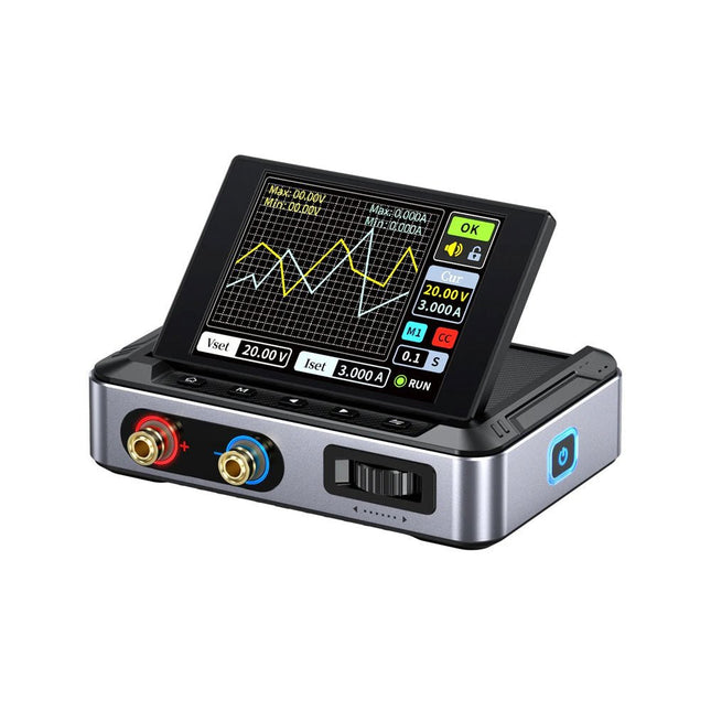
FNIRSI FNIRSI DPS150PD DC-voeding (150 W)
De FNIRSI DPS150 is een krachtige, instelbare DC-voeding met een USB-C-ingangsinterface en meerdere voedingsmodi, waardoor een nauwkeurige aanpassing van de uitgangsspanning (0-30 V) en stroom (0-5 A) mogelijk is. Het biedt een efficiënte, laag verbruik en stabiele output, uitgerust met meerdere veiligheidsbeschermingsfuncties, waaronder overspanning, overstroom, overbelasting, oververhitting en omgekeerde verbinding. Het kan flexibel worden toegepast op de seriële verbinding van meerdere apparaten, met een rijke en gebruiksvriendelijke weergave en bediening, een compact en draagbaar ontwerp en voldoet aan verschillende toepassingsbehoeften. Kenmerken 30 V, 5 A, 150 W variabel gelijkstroomvermogen met 0,01 V, 0,001 A precisie, CC/CV-modi en <20 mV rimpel om gevoelige elektronica te beschermen. Ondersteunt pc-, QC- en DC-ingangen met programmeerbare uitgangen en 6 vooraf ingestelde spannings-/stroominstellingen. Compatibel met 4 mm banaanstekkers, U-vormige aansluitingen en koperdraden voor diverse apparatuur. 8 veiligheidsmechanismen, waaronder bescherming tegen overspanning, stroom, kortsluiting en oververhitting. 2,8-inch HD IPS-scherm met 90° flip-, numerieke en curve-displays voor eenvoudige monitoring. Klein, ruimtebesparend ontwerp voor gebruik in laboratoria, reparaties en doe-het-zelf-projecten. Specificaties Ingangsspanning 5~32 V DC Ingangsstroom 100 mA-5 A Uitgangsspanning 0-30 V Uitgangsstroom 0~5 A Uitgangsvermogen 0-150 W Input way PD-snellader QC snellader Powerbank DC-voedingsadapters Bedrijfsomgeving 0-40°C Belastingsregeling 0,49% Efficiëntie bij volledige belasting 96,30% Display 2,8 inch (320 x 240) Afmetingen 106 x 76 x 28 mm Gewicht 178 g Inbegrepen 1x DPS150 voeding 2x Krokodillenklemdraden (zwart en rood) 1x C2C PD oplaadkabel 1x 100 W PD GaN-adapter (EU) 1x Micro-USB-kabel 1x Manual Downloads Manual Firmware V0.0.1
€ 95,00
-
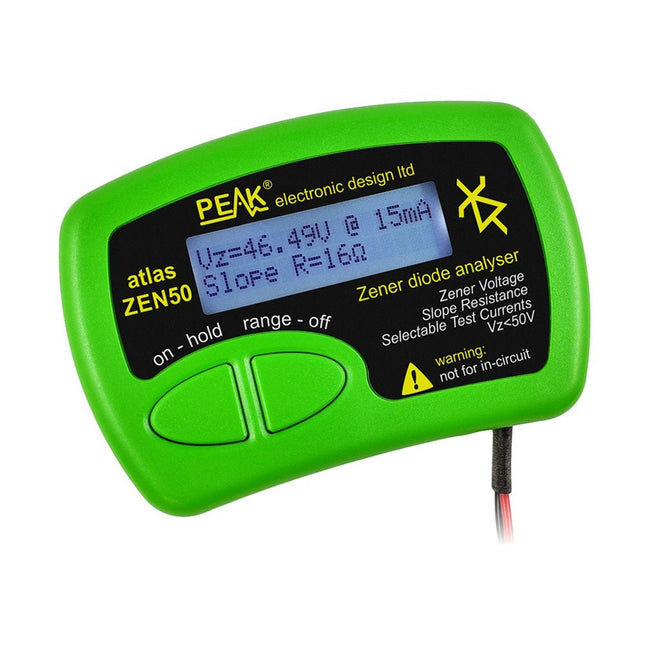
Peak Peak Atlas ZEN50 Zener Diode Analyzer
The Peak Atlas ZEN50 is ideal for testing Zener diodes (including avalanche diodes), transient suppressors, LEDs and LED strings. It generates constant current pulses (selectable from 2 mA, 5 mA, 10 mA and 15 mA) at voltages from 0V to 50V. So even high voltage Zeners or high voltage LED strings can be tested. Test currents are supplied in narrow pulses to ensure that the component under test remains at a constant temperature. The voltage of the part is displayed on the screen together with the test current and also a measure of the component's slope resistance (also known as dynamic impedance). Specificaties Analyzer type Zeners, LEDs, TVS etc Test currents 2 mA, 5 mA, 10 mA, 15 mA Voltage range 0.00 to 50.00 V Slope resistance range 0 to 8000 Ohms Battery type Single AAA (supplied). Life typically 1400 ops Test method Triple pulse burst @ 10pps (typ) Test current duty cycle 3% Display type Alphanumeric LCD (with backlight) Inbegrepen Peak Atlas ZEN50 Zener Diode Analyzer Fitted flexible test leads with gold plated crocs Comprehensive illustrated user guide AAA Alkaline battery Downloads Datasheet (EN) User Guide (EN)
€ 85,91
-

Elektor Digital Technical Modeling with OpenSCAD (E-book)
Create Models for 3D Printing, CNC Milling, Process Communication and Documentation Engineers dread designing 3D models using traditional modeling software. OpenSCAD takes a refreshing and completely different approach. Create your models by arranging geometric solids in a JavaScript-like language, and use them with your 3D printer, CNC mill, or process communication. OpenSCAD differs from other design systems in that it uses programmatical modeling. Your model is made up of primitives that are invoked using a C-, Java- or Python-like language. This approach to model design is close to the “mechanical work” done in the real world and appeals to engineers and others who are not a member of the traditional creative class. OpenSCAD also provides a wide variety of comfort functions that break the 1:1 relationship between code and geometry. This book demonstrates the various features of the programming language using practical examples such as a replacement knob for a LeCroy oscilloscope, a wardrobe hanger, a container for soap dispensers, and various other real-life examples. Written by an engineer with over 15 years of experience, this book is intended for Linux and Windows users alike. If you have programming experience in any language, this book will have you producing practical three-dimensional objects in short order!
€ 29,95
Leden: € 26,96
-

Elektor Digital Renewable Energy at Home (E-book)
A Hands-on Guide to Crafting Your Own Power Plant The book you are about to read provides a step-by-step guide for building a renewable energy power plant at home. Our goal was to make the book as practical as possible. The material is intended for immediate application with a small amount of theory. Yet, the theory is important as a foundation that saves time and effort by disabusing the readers of potential misconceptions. Specifically, upon having a firm understanding of photovoltaic physics, you will not be inclined to fruitlessly search for 90% efficient solar panels! We want our readers to be the “doers”. If the book gets covered in grime and some pages become torn while you are building your power plant – this is the best compliment to us. The book covers solar and wind energy. Also, a curious power source based on manure is discussed as well, giving the doers an opportunity to further develop the manure fuel cell. It is important to note that there are many companies offering installation of complete solar solutions. Upon installing the panels, the system is not owned by the customer. Therefore, there is no freedom for experimentation and optimization. Also, none can beat the cost of a DIY solution as well as the ultimate satisfaction. All that is written here is a result of us building a renewable energy solution in Southern California. As the book was completed, the energy began flowing!
€ 24,95
Leden: € 22,46
-

Elektor Digital Digital Electronics (E-book)
The Basics, New Ideas & Applications Build digital electronics from the ground up—and take it all the way to practical circuits you can use. This book guides you through the core principles of digital technology with a strongly hands-on approach. You’ll begin with the essentials: signals, devices for working with them, and what "logic 0" and "logic 1" mean in real hardware. Simple demonstration setups made from easy-to-find parts (LEDs, diodes, resistors, switches) help you see how logic behaves, making the theory click before you move on. From there, you’ll explore a wide range of logic elements and how they’re implemented, including classic logic families such as TTL and CMOS. The fundamentals section covers the building blocks of digital systems: flip-flops, Schmitt triggers, registers, counters and dividers, encoders/ decoders, multiplexers/demultiplexers, plus A/D and D/A conversion and timing circuits. Next, the book invites you into "new ideas" in digital electronics—universal logic elements, unconventional approaches (including thyristor-based and fractional logic), and creative logic functions that can inspire original designs. Finally, a large, well-organized collection of application circuits turns knowledge into projects: electronic switches and selectors, pulse generators, PWM regulators, frequency multipliers/dividers, phase shifters, and digital filters. Study it deeply, and you’ll gain not only understanding—but the ability to design and debug digital circuits independently.
€ 32,95
Leden: € 29,66
-
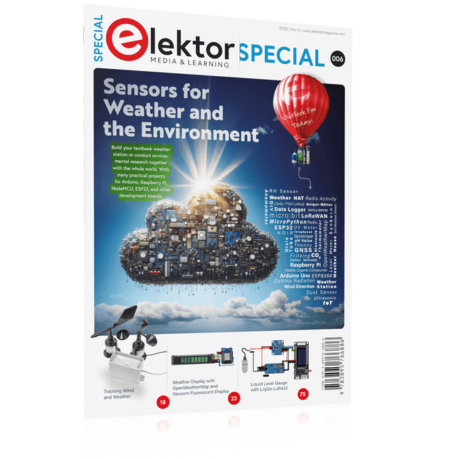
Elektor Special: Sensors for Weather and the Environment
Build your textbook weather station or conduct environmental research together with the whole world. With many practical projects for Arduino, Raspberry Pi, NodeMCU, ESP32, and other development boards. Weather stations have enjoyed great popularity for decades. Every current and even every long discontinued electronics magazine has regularly featured articles on building your own weather station. Over the years, they have become increasingly sophisticated and can now be fully integrated into an automated home — although this often requires loyalty to an (expensive) brand manufacturer across all components. With your own weather and environmental data, you can keep up and measure things that no commercial station can. It’s also fun: expand your knowledge of electronics, current microcontroller development boards and programming languages in a fun and meaningful way. For less than 10 euros you can get started and record your first environmental data — with time and growing interest, you will continue to expand your system. In this Edition Which Microcontroller Fits My Project? The Right Development Environment Tracking Wind and Weather Weather Display with OpenWeatherMap and Vacuum Fluorescent Display Volatile Organic Compounds in the Air We Breathe Working with MQ Sensors: Measuring Carbon Monoxide — Odorless but Toxic CO2 Traffic Light with ThingSpeak IoT Connection An Automatic Plant Watering System Good Indoor Climate: Temperature and Humidity are Important criteria Classy Thermometer with Vintage Tube Technology Nostalgic Weather House for the Whole Family Measuring Air Pressure and Temperature Accurately Sunburn Warning Device DIY Sensor for Sunshine Duration Simple Smartphone Says: Fog or Clear View? Identifying Earthquakes Liquid Level Measurement for Vessels and Reservoirs Water pH Value Measurement Detecting Radioactive Radiation GPS: Sensor Location Service Across the Globe Saving and Timestamping Log Files on SD Cards LoRaWAN, The Things Network, and ThingSpeak Operating a LoRaWAN Gateway for TTN Defying "Wind and Weather" Mega Display with Weather Forecasz
€ 19,95
Leden: € 17,96
-

Elektor Academy Pro Arduino (programmeercursus)
Deze complete microcontroller-programmeercursus op basis van de Arduino Uno bevat een leerboek, een componentenkit, praktische projecten en een uitgebreide online cursus met simulaties. Ideaal om embedded systems stap voor stap te leren programmeren met Arduino via een praktische hands-on aanpak. Een praktische introductie tot embedded systems met de Arduino Uno Deze cursus is ontworpen voor beginners in embedded systems die op zoek zijn naar een gestructureerde en voorbeeldgerichte start. Een kit met LED’s en weerstanden, schakelaars, sensoren en actuatoren, displays, een breadboard en draden is inbegrepen. Deze worden in de cursus gebruikt om voorbeeldtoepassingen te demonstreren. Er is geen voorkennis van Arduino of embedded ontwikkeling vereist. Elke sectie bevat praktische voorbeelden en mini-projecten om belangrijke concepten te versterken en verdere verkenning te stimuleren. Aan het einde van de cursus kunt u niet alleen de voorbeelden reproduceren, maar ook uitbreiden met uw eigen ideeën en toepassingen. Wat leert u? Microcontrollerprogrammering met Arduino met behulp van het Uno R3 board Werken met digitale I/O, knoppen en encoders uitlezen, LED’s en relais aansturen Analoge ingangen, spanningen en sensoren uitlezen Genereren van analoge uitgangssignalen en PWM Gebruik van seriële communicatie zoals UART, I²C en SPI om displays aan te sturen en digitale sensoren en SD-kaarten uit te lezen Tijdbeheer Werken met interrupts Realtime sensorinput en besturing via knoppen, LED’s en displays Aansturen van actuatoren zoals relais en servomotoren Voor wie is dit? Studenten en zelflerenden die embedded systems willen ontdekken Makers en IoT-enthousiastelingen die hun hardwarevaardigheden willen verbeteren Docenten en trainers die kant-en-klaar lesmateriaal zoeken Wat zit er in de doos? Toegang tot de volledige cursus op het Elektor Academy Pro leerplatform Uno R3 microcontrollerboard + USB-kabel Boek: Programming Microcontrollers in C/C++ Using Arduino Downloadbare projectbestanden voor elke module Componentenkit: 2× LED, rood, 5 mm LED, groen, 5 mm 3× weerstand, 470 Ω, 0,25 W LDR Potentiometer, 10 kΩ, lineair Drukknop Rotary encoder module Relaismodule DHT22 temperatuur- en vochtigheidssensor TM1637-compatibel 4-digit 7-segment display MPU-6050 IMU met headers SSD1306-compatibel I²C OLED display Micro SD-kaartadapter met header Buzzer SG90 micro servo ILI9341-compatibel SPI 240×320 TFT display 20× jumper wires Breadboard Alle programmeercursussen (en verschillen in inhoud) Cursus Arduino Raspberry Pi Pico with Arduino C/C++ ESP32 with Arduino C/C++ Raspberry Pi Pico with MicroPython ESP32 with MicroPython Online cursus Access to Arduino Course Access to Pico with Arduino C/C++ Course Access to ESP32 with Arduino C/C++ Course Access to Pico with MicroPython Course Access to ESP32 with MicroPython Course Board Uno R3 Raspberry Pi Pico ESP32 Raspberry Pi Pico ESP32 Boek Programming Microcontrollers in C/C++ Using Arduino Programming Microcontrollers in C/C++ Using Arduino Programming Microcontrollers in C/C++ Using Arduino Programming Microcontrollers in MicroPython Programming Microcontrollers in MicroPython Kit 40-delige componenten-kit 40-delige componenten-kit 40-delige componenten-kit 40-delige componenten-kit 40-delige componenten-kit
€ 69,95
Leden: € 62,96
-
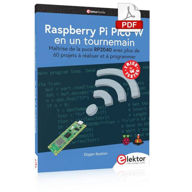
Elektor Digital Raspberry Pi Pico W en un tournemain (PDF)
Maîtrise de la puce RP2040 avec plus de 60 projets à réaliser et à programmer Les cartes Raspberry Pi Pico et Pico W sont animées par un microcontrôleur ARM Cortex M0+ RP2040 à double coeur, rapide, efficace et peu coûteux, qui fonctionne jusqu'à 133 MHz et dispose de 264 Ko de SRAM et de 2 Mo de mémoire Flash. Outre une vaste mémoire, le Pico et le Pico W disposent de nombreuses broches GPIO et d'interfaces telles que CA/N, SPI, I²C, UART, MLI, de fonctions de temporisation, d'une interface de débogage matériel et d'un capteur de température interne. La carte Raspberry Pi Pico W comporte en plus une puce CYW43439 Bluetooth et Wi-Fi d'Infineon. Au moment de la rédaction de ce livre, le micrologiciel Bluetooth pour le Pico W n'était pas encore disponible. Le Wi-Fi à 2,4 GHz est toutefois entièrement pris en charge avec les protocoles 802.11b/g/n. Ce livre est une introduction à l'utilisation du Raspberry Pi Pico W avec le langage de programmation MicroPython. Les quelque soixante projets testés et opérationnels sont présentés à l'aide de l'environnement de développement intégré (EDI) Thonny. Les sujets abordés sont nombreux : Installation de MicroPython sur le Raspberry Pi Pico depuis un PC Interruptions de l'horloge et interruptions externes Convertisseur analogique-numérique (CA/N) Capteurs de température interne et externe Capteurs externes (pression, humidité, pouls, à ultrasons) Enregistrement de données MLI, UART, I²C et SPI Bluetooth, Wi-Fi et applis sur smarphone Convertisseur numérique-analogique (CN/A) Tous les projets ont été testés et éprouvés. Ils peuvent être mis en oeuvre sur le Raspberry Pi Pico ainsi que sur le Raspberry Pi Pico W. Toutefois les projets avec une liaison Wi-Fi ne fonctionnent que sur le Pico W. Une petite expérience en programmation et en électronique est nécessaire pour suivre les projets. De brèves descriptions, des schémas fonctionnels, des schémas détaillés du câblage des montages et des listings MicroPython complets sont fournis pour tous les projets.
€ 34,95
Leden: € 31,46
-

Elektor Academy Pro Raspberry Pi Pico with Arduino C/C++ (programmeercursus)
Deze complete microcontroller-programmeercursus op basis van de Raspberry Pi Pico bevat een leerboek, een componentenkit, praktische projecten en een uitgebreide online cursus met simulaties. Ideaal om embedded systems stap voor stap te leren programmeren met Arduino via een praktische hands-on aanpak. Een praktische introductie tot embedded systems met de Raspberry Pi Pico Deze cursus is ontworpen voor beginners in embedded systems die op zoek zijn naar een gestructureerde en voorbeeldgerichte start. Een kit met LED’s en weerstanden, schakelaars, sensoren en actuatoren, displays, een breadboard en draden is inbegrepen. Deze worden in de cursus gebruikt om voorbeeldtoepassingen te demonstreren. Er is geen voorkennis van Arduino of embedded ontwikkeling vereist. Elke sectie bevat praktische voorbeelden en mini-projecten om belangrijke concepten te versterken en verdere verkenning te stimuleren. Aan het einde van de cursus kunt u niet alleen de voorbeelden reproduceren, maar ook uitbreiden met uw eigen ideeën en toepassingen. Wat leert u? Microcontroller programmeren in C/C++ met de Raspberry Pi Pico met behulp van de Arduino IDE Werken met digitale I/O, knoppen en encoders uitlezen, LED’s en relais aansturen Analoge ingangen, spanningen en sensoren uitlezen Genereren van analoge uitgangssignalen en PWM Gebruik van seriële communicatie zoals UART, I²C en SPI om displays aan te sturen en digitale sensoren en SD-kaarten uit te lezen Tijdbeheer Werken met interrupts Realtime sensorinput en besturing via knoppen, LED’s en displays Aansturen van actuatoren zoals relais en servomotoren Voor wie is dit? Studenten en zelflerenden die embedded systems willen ontdekken Makers en IoT-enthousiastelingen die hun hardwarevaardigheden willen verbeteren Docenten en trainers die kant-en-klaar lesmateriaal zoeken Wat zit er in de doos? Toegang tot de volledige cursus op het Elektor Academy Pro leerplatform Raspberry Pi Pico microcontrollerboard + USB-kabel Boek: Programming Microcontrollers in C/C++ Using Arduino Downloadbare projectbestanden voor elke module Componentenkit: 2× LED, rood, 5 mm LED, groen, 5 mm 3× weerstand, 470 Ω, 0,25 W LDR Potentiometer, 10 kΩ, lineair Drukknop Rotary encoder module Relaismodule DHT22 temperatuur- en vochtigheidssensor TM1637-compatibel 4-digit 7-segment display MPU-6050 IMU met headers SSD1306-compatibel I²C OLED display Micro SD-kaartadapter met header Buzzer SG90 micro servo ILI9341-compatibel SPI 240×320 TFT display 20× jumper wires Breadboard Alle programmeercursussen (en verschillen in inhoud) Cursus Arduino Raspberry Pi Pico with Arduino C/C++ ESP32 with Arduino C/C++ Raspberry Pi Pico with MicroPython ESP32 with MicroPython Online cursus Access to Arduino Course Access to Pico with Arduino C/C++ Course Access to ESP32 with Arduino C/C++ Course Access to Pico with MicroPython Course Access to ESP32 with MicroPython Course Board Uno R3 Raspberry Pi Pico ESP32 Raspberry Pi Pico ESP32 Boek Programming Microcontrollers in C/C++ Using Arduino Programming Microcontrollers in C/C++ Using Arduino Programming Microcontrollers in C/C++ Using Arduino Programming Microcontrollers in MicroPython Programming Microcontrollers in MicroPython Kit 40-delige componenten-kit 40-delige componenten-kit 40-delige componenten-kit 40-delige componenten-kit 40-delige componenten-kit
€ 69,95
Leden: € 62,96
-

Elektor Labs Elektor Zandklok voor Raspberry Pi Pico (incl. Laserkop Upgrade)
Dit bundel bevat de populaire Elektor zandklok voor Raspberry Pi Pico en de nieuwe Elektor laserkop upgrade, en biedt daarmee nog meer mogelijkheden om de tijd weer te geven. U kunt de actuele tijd nu niet alleen in zand "graveren", maar ook op een lichtgevende folie schrijven of groene tekeningen maken. Inhoud van de bundel Elektor Zandklok voor Raspberry Pi Pico (normale prijs: € 50) Elektor Laserkop Upgrade voor Zandklok (normale prijs: € 35) Zandklok voor Raspberry Pi (een op de Raspberry Pi Pico gebaseerde Eye Catcher) Een standaard zandklok laat meestal slechts zien hoe de tijd verstrijkt. Deze door een Raspberry Pi Pico aangestuurde zandklok toont daarentegen de exacte tijd door de vier cijfers voor uren en minuten in een zandlaag te "graveren". Na een vooraf ingestelde periode wordt het zand door twee trilmotoren vlak getrild en begint alles weer van voren af aan. Het hart van de zandklok wordt gevormd door twee servomotoren, die via een pantograafmechanisme een schrijfpen aandrijven. Een derde servomotor tilt deze pen op en neer. Het zandbakje is voorzien van twee trilmotoren om het zand weer vlak te trillen. Het elektronische deel van de zandklok bestaat uit een Raspberry Pi Pico en een RTC/driverbord met een real-time klok, plus drivercircuits voor de servomotoren. Een gedetailleerde bouwhandleiding is beschikbaar via download. Kenmerken Afmetingen: 135 x 110 x 80 mm Bouwtijd: ca. 1,5 tot 2 uur Inbegrepen 3x Voorgesneden acrylaatplaten met alle mechanische onderdelen 3x Mini servomotoren 2x Trilmotoren 1x Raspberry Pi Pico 1x RTC/driverkaart met geassembleerde onderdelen Moeren, boutjes, afstandhouders en draden voor de montage Fijnkorrelig wit zand Elektor Laserkop Upgrade voor Zandklok De nieuwe Elektor Laserkop transformeert de Elektor Zandklok in een klok die de tijd op glow-in-the-dark-film schrijft in plaats van op zand. Naast het weergeven van de tijd kan het ook worden gebruikt om kortstondige tekeningen te maken. De 5 mW laserpointer, met een golflengte van 405 nm, produceert heldergroene tekeningen op de glow-in-the-dark-film. Voor het beste resultaat gebruikt u de kit in een slecht verlichte kamer. Waarschuwing: Kijk nooit rechtstreeks in de laserstraal! De kit bevat alle benodigde componenten, maar het solderen van drie draden is vereist. Opmerking: Deze kit is ook compatibel met de originele Arduino-gebaseerde Zandklok uit 2017. Voor meer details, zie Elektor 1-2/2017 en Elektor 1-2/2018.
€ 84,95€ 69,95Beste prijs
-
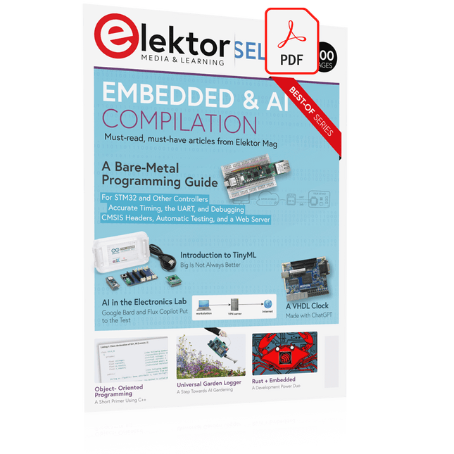
Elektor Digital Elektor Select: Embedded & AI (PDF)
This collection features the best of Elektor Magazine's articles on embedded systems and artificial intelligence. From hands-on programming guides to innovative AI experiments, these pieces offer valuable insights and practical knowledge for engineers, developers, and enthusiasts exploring the evolving intersection of hardware design, software innovation, and intelligent technology. Contents Programming PICs from the Ground UpAssembler routine to output a sine wave Object-Oriented ProgrammingA Short Primer Using C++ Programming an FPGA Tracking Down Microcontroller Buffer Overflows with 0xDEADBEEF Too Quick to Code and Too Slow to Test? Understanding the Neurons in Neural NetworksEmbedded Neurons MAUI Programming for PC, Tablet, and SmartphoneThe New Framework in Theory and Practice USB Killer DetectorBetter Safe Than Sorry Understanding the Neurons in Neural NetworksArtificial Neurons A Bare-Metal Programming Guide Part 1: For STM32 and Other Controllers Part 2: Accurate Timing, the UART, and Debugging Part 3: CMSIS Headers, Automatic Testing, and a Web Server Introduction to TinyMLBig Is Not Always Better Microprocessors for Embedded SystemsPeculiar Parts, the Series FPGAs for BeginnersThe Path From MCU to FPGA Programming AI in Electronics DevelopmentAn Update After Only One Year AI in the Electronics LabGoogle Bard and Flux Copilot Put to the Test ESP32 and ChatGPTOn the Way to a Self-Programming System… Audio DSP FX Processor Board Part 1: Features and Design Part 2: Creating Applications Rust + EmbeddedA Development Power Duo A Smart Object CounterImage Recognition Made Easy with Edge Impulse Universal Garden LoggerA Step Towards AI Gardening A VHDL ClockMade with ChatGPT TensorFlow Lite on Small MicrocontrollersA (Very) Beginner’s Point of View Mosquito DetectionUsing Open Datasets and Arduino Nicla Vision Artificial Intelligence Timeline Intro to AI AlgorithmsPrompt: Which Algorithms Implement Each AI Tool? Bringing AI to the Edgewith ESP32-P4 The Growing Role of Edge AIA Trend Shaping the Future
€ 9,95
Leden: € 8,96
-

Elektor Digital Basiscursus Elektronica (E-BOOK)
Er zijn talloze diepgravende elektronica-leerboeken op de markt. We noemen er hier slechts één: ‘The Art of Electronics’, dat onder de titel ‘Elektronica, kunst en kunde’ in vier delen bij Elektor is verschenen. Wie echter elektronicakennis voor “dagelijks gebruik” wil hebben, zit op zo’n wetenschappelijk verantwoorde verhandeling waarschijnlijk helemaal niet te wachten. Laat staan op een beschrijving van de meest exotische componenten of elke denkbare variant van een principiële schakeling.Indien dit ook voor u geldt, dan is dit boek voor u bestemd: voor de middelbare scholier en voor de hobbyist die zich meer wil verdiepen in de elektronica. En dus voor iedereen die een korte, begrijpelijke en bovenal betaalbare inleiding tot dit interessante vakgebied wenst. Deze ‘Basiscursus Elektronica’ maakt u vertrouwd met de analoge (laagfrequent-)techniek, letterlijk de basis van alle elektronica.
€ 24,95
Leden: € 22,46
-

Würth Abc of Power Modules (E-book)
Functionality, structure and handling of a power module For readers with first steps in power management the “Abc of Power Modules” contains the basic principles necessary for the selection and use of a power module. The book describes the technical relationships and parameters related to power modules and the basis for calculation and measurement techniques. Contents Basics This chapter describes the need of a DC/DC voltage converter and its basic functionality. Furthermore, various possibilities for realizing a voltage regulator are presented and the essential advantages of a power module are mentioned. Circuit topologies Circuit concepts, buck and boost topologies very frequently used with power modules are explained in detail and further circuit topologies are introduced. Technology, construction and regulation technology The mechanical construction of a power module is presented, which has a significant influence on EMC and thermal performance. Furthermore, control methods are explained and circuit design tips are provided in this chapter. Measuring methods Meaningful measurement results are absolutely necessary to assess a power module. The relevant measurement points and measurement methods are described in this chapter. Handling The aspects of storage and handling of power modules are explained, as well as their manufacturing and soldering processes. Selection of a power modules Important parameters and criteria for the optimal selection of a power module are presented in this section.
€ 8,99
Leden: € 8,09
-
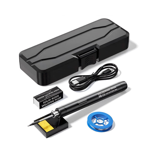
Generic Smart USB Soldeerbout Kit
De Smart USB Soldeerbout Kit is een compacte, draadloze oplossing, ontworpen voor precisie en draagbaarheid. Met intelligente temperatuurregeling met drie snelheden (300-450°C) en een gemakkelijk afleesbaar LED-display, warmt hij op in slechts 10 seconden en smelt het soldeer in slechts 6 seconden. De oplaadbare batterij van 1000 mAh biedt tot 30 minuten continu gebruik, waardoor hij ideaal is voor snelle reparaties, elektronicaprojecten en doe-het-zelfklussen. Met een plug-and-play, vervangbare punt en een hittebestendige, geïsoleerde behuizing is hij veilig, gebruiksvriendelijk en perfect voor zowel beginners als professionals onderweg. Kenmerken Intelligente temperatuurregeling met drie snelheden: Voorzien van een led-display met instelbare temperaturen tussen 300 en 450°C. Schakel eenvoudig tussen Celsius en Fahrenheit. Geïntegreerde plug-in soldeerboutpunt: Plug-and-play ontwerp. De punt kan worden vervangen door deze eenvoudig los te draaien, voor een snelle en gemakkelijke bediening. Veilig en duurzaam ontwerp: Hittebestendige, geïsoleerde behuizing voor extra veiligheid tijdens gebruik. Batterijcapaciteit: Uitgerust met een oplaadbare batterij van 1000 mAh die tot 30 minuten continu gebruik ondersteunt op een volle lading – ideaal voor dagelijkse taken. Efficiënte prestaties: 8 W vermogen met een geïntegreerde verwarmingskern voor snelle opwarming. Smelt tin in slechts 6 seconden en biedt uitstekende thermische geleiding. Gebruiksvriendelijk: Na het inschakelen via USB stelt u de gewenste temperatuur in. De soldeerbout warmt op in 10 seconden. Zodra de soldeerbout klaar is, plaatst u de punt op de standaard – deze koelt binnen 1 minuut af. Perfect voor beginners, hobbyisten, eenvoudige klusjes in huis en het opleiden van ingenieurs. Draadloze innovatie: Deze draadloze soldeerset bevat een ingebouwde oplaadbare lithium-ionbatterij, waardoor kabels niet meer nodig zijn. Veelzijdig te gebruiken voor het solderen van printplaten, elektrische reparaties, het maken van sieraden, metaalbewerking, computeronderhoud en doe-het-zelfprojecten. Specificaties Instelbare temperatuur: 300-450°C Smelttijd tin: <15 seconden Werkspanning: 5 V Uitgangsvermogen: 8 W Batterijcapaciteit: 1000 mAh Automatische slaapfunctie: Activeert na 10 minuten inactiviteit Oplaadtijd: ca. 90 minuten Batterijduur: Tot 30 minuten continu gebruik Oplaadinterface: USB-C Materiaal: Aluminiumlegering Afmetingen: 190 x 16 mm Inbegrepen 1x USB Soldeerbout 1x Soldeerpunt 1x Soldeerhars 1x Soldeerbouthouder (met spons) 1x USB-C oplaadkabel 1x Soldeerdraad 1x Opbergdoos
€ 34,95€ 17,50Beste prijs
-
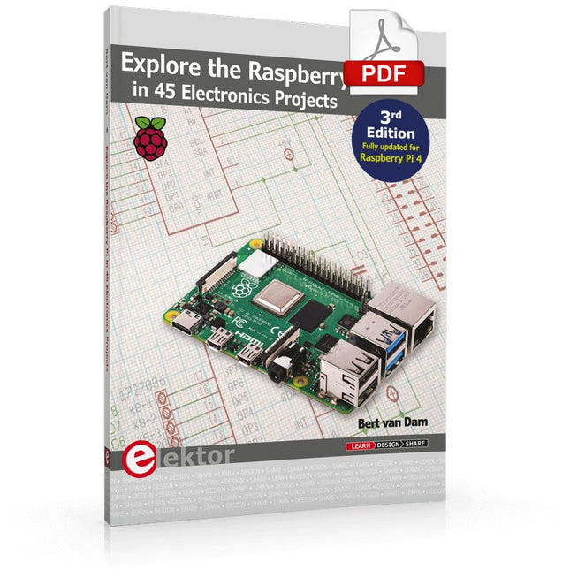
Elektor Digital Explore the Raspberry Pi in 45 Electronics Projects (3rd Edition | E-book)
3rd Edition – Fully updated for Raspberry Pi 4 The Raspberry Pi is a very cheap but complete computer system that allows all sorts of electronics parts and extensions to be connected. This book addresses one of the strongest aspects of the Raspberry Pi: the ability to combine hands-on electronics and programming. Combine hands-on electronics and programming After a short introduction to the Raspberry Pi you proceed with installing the required software. The SD card that can be purchased in conjunction with this book contains everything to get started with the Raspberry Pi. At the side of the (optional) Windows PC, software is used which is free for downloading. The book continues with a concise introduction to the Linux operating system, after which you start programming in Bash, Python 3 and Javascript. Although the emphasis is on Python, the coverage is brief and to the point in all cases – just enabling you to grasp the essence of all projects and start adapting them to your requirements. All set, you can carry on with fun projects. The book is ideal for self-study No fewer than 45 exciting and compelling projects are discussed and elaborated in detail. From a flashing lights to driving an electromotor; from processing and generating analog signals to a lux meter and a temperature control. We also move to more complex projects like a motor speed controller, a web server with CGI, client-server applications and Xwindows programs. Each project has details of the way it got designed that way The process of reading, building, and programming not only provides insight into the Raspberry Pi, Python, and the electronic parts used, but also enables you to modify or extend the projects any way you like. Also, feel free to combine several projects into a larger design.
€ 32,95
Leden: € 29,66
-

Elektor Publishing MIT App Inventor for AI and IoT
Build Smart Applications with Raspberry Pi, Arduino, and ESP32 Discover how easy and exciting mobile app development can be with MIT App Inventor. This hands-on guide takes you from basic concepts to building real-world mobile applications using a simple visual programming approach—no prior coding experience required. You will create IoT and AI-powered apps for Android devices and explore how App Inventor can also be used with iPhones and iPads. Connect your applications to platforms such as Arduino UNO R4 WiFi, ESP32, Raspberry Pi Pico (2)W and Raspberry Pi 5, enabling you to build smart, connected systems. Inside the book, you will learn how to: Build interactive apps using buttons, images, sound, and multimedia Create text-to-speech and speech-recognition applications Develop camera-based and location-aware (GPS) apps Design useful tools such as calculators and educational apps Work with smartphone sensors like accelerometers and light sensors Build AI-powered applications, including voice assistants and image-generation features Send and receive messages, and create communication-based apps Connect mobile apps to hardware using Wi-Fi and Bluetooth Control real devices such as LEDs, motors, and sensors Designed for beginners, students, and hobbyists, this book focuses on learning by doing. By the end, you will have the skills and confidence to create your own innovative applications that interact with both the digital and physical worlds. Start building and turning your ideas into reality.
€ 44,95
Leden: € 40,46
-

OWON OWON HDS272S 2-kanaals oscilloscoop (70 Mhz) + Multimeter + Signaalgenerator
De OWON HDS272S is de perfecte alles-in-één oplossing!Oscilloscoop, multimeter en signaalgenerator in hetzelfde accu-gevoede apparaat, om overal mee te kunnen werken.Features Oscilloscoop + multimeter + signaalgenerator, multifunctioneel in één apparaat 3,5-inch lcd-kleurenscherm met hoge resolutie en hoog contrast, geschikt voor gebruik buitenshuis 18650 lithium accu, weinig stroomverbruik ≤3 W, kan ongeveer 6 uur continu werken USB Type-C interface, ondersteuning voor powerbank, ondersteuning voor PC-verbinding Zelfkalibratie functie Ondersteunt SCPI, faciliteert secundary development Specificaties Oscilloscoop Bandbreedte 70 MHz Kanalen 2-kanaals oscilloscoop + 1-kanaals generator Sample rate 250 MSa/s Acquisitie model Normaal, Peak detectie Record lengte 8K Beeldscherm 3,5-inch LCD Vernieuwingsfrequentie golfvorm 10.000 wfrms/s Ingang DC, AC en Aarde Input Impedantie 1 MΩ±2%, met parallel 16pF±10pF Probe dempingsfactoren 1x, 10x, 100x, 1000x, 10000x Maximale ingangsspanning 400 V (DC+AC, PK-PK, 1MΩ ingangsimpedantie) (10:1 sondedemping) Bandbreedte limiet (standaard) 20 MHz Horizontale schaal 5 ns/div - 1000 s/div, in stappen van 1 - 2 - 5 Verticale gevoeligheid 10 mV/div - 10 V/div Verticale resolutie 8 bits Trigger type Edge Trigger modi Auto, Normaal, Enkel Automatische meting Periode, Frequentie, Gemiddeld, PK-PK, Max, Min Cursor meting ΔV, ΔT, ΔT&ΔV tussen cursors Communicatie interface USB Type-C Multimeter Maximale resolutie 20.000 counts Testmodus Spanning, Stroom, Weerstand, Capaciteit, Diode en Continuïteit test Ingangsimpedantie 10 MΩ Maximale ingangsspanning AC 750 V, DC 1000V Maximale ingangsstroom DC: 10A , AC: 10A Diode 0-2 V Signaalgenerator Frequentie uitgang Sinus 0,1 Hz - 25 MHz Square 0,1 Hz - 5 MHz Ramp 0,1 Hz - 1 MHz Pulse 0,1 Hz - 5 MHz Arbitrary 0,1 Hz - 5 MHz Sample rate 125 MSa/s Kanalen 1-kanaals Amplitude Bereik 20 mVpp - 5 Vpp Golfvorm lengte 8K Verticale resolutie 14 bits Uitgangs impedantie 50Ω Downloads User Manual for HDS200 Series SCPI Protocol for HDS200 Series Quick Guide for HDS200 Series PC Software for OWON HDS200 Series
€ 199,65
-
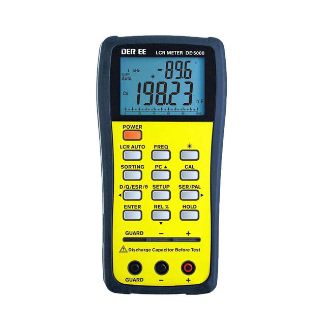
DER EE DER EE DE-5000 LCR-meter (100 kHz)
De DE-5000 is een slimme, zeer nauwkeurige, flexibele en gebruiksvriendelijke draagbare LCR-meter. Hij beschikt over automatische LCR-check, 4-draads Kelvin-meting, een backlit display met 19999 / 1999 counts, meerdere meetmodi, en instelbare testfrequenties (100 Hz, 120 Hz, 1 kHz, 10 kHz of 100 kHz). De DE-5000 LCR-meter is een handig hulpmiddel voor ingenieurs of technici. Kenmerken Automatische L.C.R. check Ls/Lp/Cs/Cp/Rs/Rp/DCR met D/Q/?/ESR meting 4-draads Kelvin-meting 19999 / 1999 counts display Achtergrondverlichting Relatieve modus Serieel/parallel modus Componenten sorteerfunctie Indicatie bij 'accu bijna leeg' Automatische power-off Specificaties Test frequentie 100 Hz / 120 Hz / 1 kHz / 10 kHz / 100 kHz Weerstand bereik 20.000 ? – 200,0 M? DCR bereik 200.00 ? – 200.0 M? Capaciteit bereik 200.00 pF – 20.00 mF Inductie bereik 20.000 ?H – 2.000 KH Display (backlit LCD-scherm) 19999 / 1999 counts Instelbare tolerantie ±0,25%, ±0,5%, ±1%, ±2%, ±5%, ±10%, ±20% Voeding 9 V accu Afmetingen 188 x 95 x 52 mm Gewicht 350 g (exclusief accu) Inbegrepen DE-5000 LCR-meter Meetconnector met krokodillenklemmen (TL-21) AC/DC-adapter Guard kabeltje (TL-23) TL-22 SMD pincetten 9 V accu Draagtas Handleiding Downloads Datasheet
€ 192,39
-

Elektor Digital Wireless Power Design (E-book)
From Theory to Practical Applications in Wireless Energy Transfer and Harvesting Wireless power transmission has gained significant global interest, particularly with the rise of electric vehicles and the Internet of Things (IoT). It’s a technology that allows the transfer of electricity without physical connections, offering solutions for everything from powering small devices over short distances to long-range energy transmission for more complex systems. Wireless Power Design provides a balanced mix of theoretical knowledge and practical insights, helping you explore the potential of wireless energy transfer and harvesting technologies. The book presents a series of hands-on projects that cover various aspects of wireless power systems, each accompanied by detailed explanations and parameter listings. The following five projects guide you through key areas of wireless power: Project 1: Wireless Powering of Advanced IoT Devices Project 2: Wireless Powered Devices on the Frontline – The Future and Challenges Project 3: Wireless Powering of Devices Using Inductive Technology Project 4: Wireless Power Transmission for IoT Devices Project 5: Charging Robot Crawler Inside the Pipeline These projects explore different aspects of wireless power, from inductive charging to wireless energy transmission, offering practical solutions for real-world applications. The book includes projects that use simulation tools like CST Microwave Studio and Keysight ADS for design and analysis, with a focus on practical design considerations and real-world implementation techniques.
€ 32,95
Leden: € 29,66
-

Elektor Labs Elektor Laserkop Upgrade voor Zandklok
De Elektor Laserkop transformeert de Elektor Sand Clock in een klok die de tijd op glow-in-the-dark-film schrijft in plaats van op zand. Naast het weergeven van de tijd kan het ook worden gebruikt om kortstondige tekeningen te maken. De 5 mW laserpointer, met een golflengte van 405 nm, produceert heldergroene tekeningen op de glow-in-the-dark-film. Voor het beste resultaat gebruikt u de kit in een slecht verlichte kamer. Waarschuwing: Kijk nooit rechtstreeks in de laserstraal! De kit bevat alle benodigde componenten, maar het solderen van drie draden is vereist. Opmerking: Deze kit is ook compatibel met de originele Arduino-gebaseerde Zandklok uit 2017. Voor meer details, zie Elektor 1-2/2017 en Elektor 1-2/2018.
€ 34,95€ 24,95Beste prijs
-

Édition spéciale : Les capteurs météorologiques et environnementaux
Construisez votre station météo idéale ou explorez les données environnementales avec le monde entier. Avec de nombreux projets pratiques pour Arduino, Raspberry Pi, NodeMCU, ESP32 et autres cartes de développement. Les stations météo jouissent d’une grande popularité depuis des décennies. Tous les magazines d’électronique, qu’ils soient récents ou non, ont publié et publient régulièrement des articles sur la construction d’une station météo. Au fil des années, elles sont devenues de plus en plus sophistiquées et peuvent aujourd’hui être entièrement intégrées dans la maison intelligente. Ceci implique toutefois souvent une fidélité à un fabricant de produits de marque (coûteux) pour tous les composants. Cependant, avec votre propre station météo, vous pouvez facilement suivre le rythme et même capturer des relevés que les appareils commerciaux ne peuvent pas réaliser. Le plaisir ne manque pas : vous développerez de manière ludique vos connaissances en électronique, en cartes de développement de microcontrôleurs modernes et en langages de programmation. Pour moins de dix euros, vous pouvez collecter des données environnementales initiales et étendre votre système au fur et à mesure que votre intérêt grandit. Dans ce numéro Sur la route du vent et de la météo Écran météo OpenWeatherMap à affichage fluorescent Les composés organiques volatils dans l‘air que nous respirons Travailler avec les capteurs MQ : mesurer le monoxyde de carbone Détecteur de CO2 avec connexion IdO vers ThingSpeak Un arrosage automatique pour vos plantes Un climat intérieur sain : la température et l‘humidité de l‘air sont importants Thermomètre avec tubes Nixie Une maison météo rétro pour toute la famille Mesurez la pression atmosphérique et la température avec précision Un détecteur de coups de soleil Capteur maison pour la durée d‘ensoleillement Le smartphone l‘indique : brouillard ou bonne visibilité ? Détecter les tremblements de terre Les niveaux des cours d‘eau et des réservoirs Évaluer la valeur du pH de l’eau Détecter les rayonnements radioactifs Avec le GPS, vous savez où se trouve votre capteur Enregistrer les fichiers journaux avec horodatage sur des cartes SD LoRaWAN, The Things Network et ThingSpeak Exploiter la passerelle LoRaWAN pour le TTN Affichage géant à led avec prévisions météo
€ 15,50
Leden: € 13,95


