Producten
-
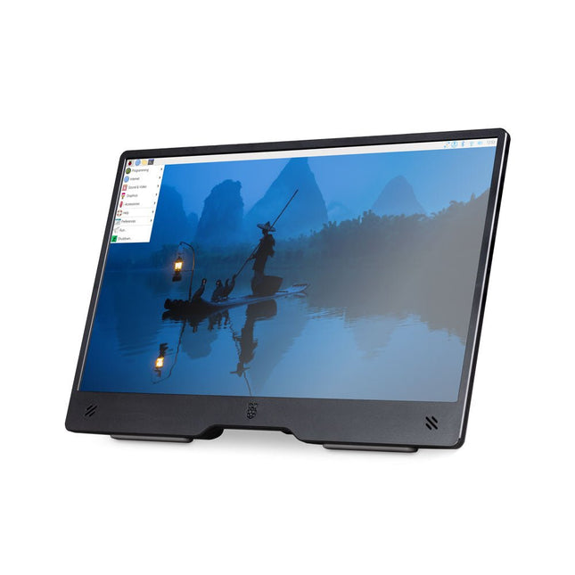
Raspberry Pi Foundation Raspberry Pi Monitor (zwart)
De Raspberry Pi Monitor is een 15,6-inch Full HD-computerscherm. Gebruiksvriendelijk, veelzijdig, compact en betaalbaar, het is de perfecte desktop-displaygenoot voor zowel Raspberry Pi-computers als andere apparaten. Met ingebouwde audio via twee naar voren gerichte luidsprekers, VESA- en schroefmontagemogelijkheden en een geïntegreerde in hoek verstelbare standaard is de Raspberry Pi Monitor ideaal voor desktopgebruik of voor integratie in projecten en systemen. Hij kan rechtstreeks van een Raspberry Pi worden voorzien, of via een aparte voeding. Kenmerken 15,6-inch Full HD 1080p IPS-scherm Geïntegreerde in hoek verstelbare standaard Ingebouwde audio via twee naar voren gerichte luidsprekers Audio-uitgang via 3,5 mm-aansluiting HDMI-ingang op volledige grootte VESA- en schroefmontageopties Volume- en helderheidsknoppen USB-C-voedingskabel Specificaties Display Schermgrootte: 15,6 inch, verhouding 16:9 Paneeltype: IPS LCD met antireflectiecoating Weergaveresolutie: 1920 x 1080 Kleurdiepte: 16,2M Helderheid (typisch): 250 nits Kleurgamma: 45% Kijkhoek: 80° Voeding 1,5 A/5 V Kan rechtstreeks worden gevoed via een Raspberry Pi USB poort (max 60% helderheid, 50% volume) of via een aparte voeding (max 100% helderheid, 100% volume) Connectiviteit Standaard HDMI-poort (compatibel met 1.4) 3,5 mm stereohoofdtelefoonaansluiting USB-C (voeding in) Audio 2x 1,2 W geïntegreerde luidsprekers Ondersteuning voor bemonsteringsfrequenties van 44,1 kHz, 48 kHz en 96 kHz Downloads Datasheet
-
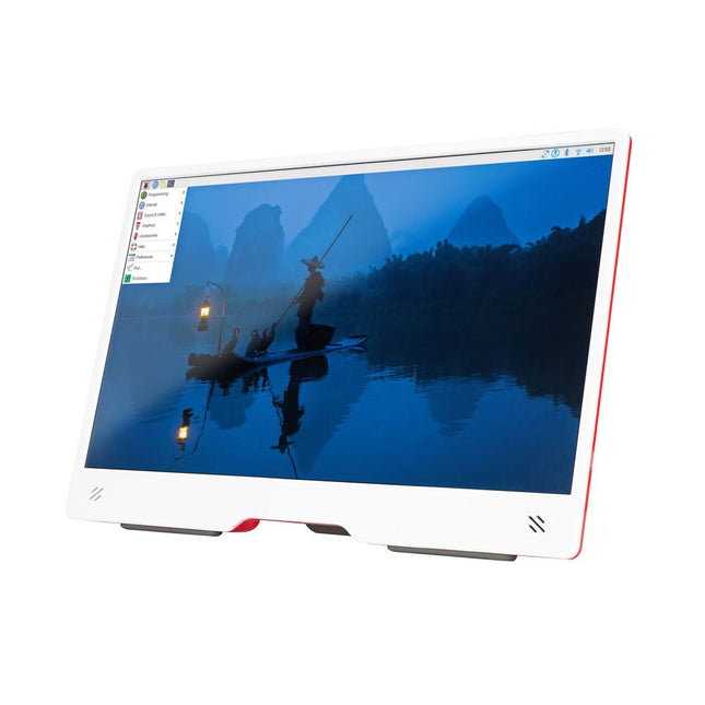
Raspberry Pi Foundation Raspberry Pi Monitor (wit/rood)
De Raspberry Pi Monitor is een 15,6-inch Full HD-computerscherm. Gebruiksvriendelijk, veelzijdig, compact en betaalbaar, het is de perfecte desktop-displaygenoot voor zowel Raspberry Pi-computers als andere apparaten. Met ingebouwde audio via twee naar voren gerichte luidsprekers, VESA- en schroefmontagemogelijkheden en een geïntegreerde in hoek verstelbare standaard is de Raspberry Pi Monitor ideaal voor desktopgebruik of voor integratie in projecten en systemen. Hij kan rechtstreeks van een Raspberry Pi worden voorzien, of via een aparte voeding. Kenmerken 15,6-inch Full HD 1080p IPS-scherm Geïntegreerde in hoek verstelbare standaard Ingebouwde audio via twee naar voren gerichte luidsprekers Audio-uitgang via 3,5 mm-aansluiting HDMI-ingang op volledige grootte VESA- en schroefmontageopties Volume- en helderheidsknoppen USB-C-voedingskabel Specificaties Display Schermgrootte: 15,6 inch, verhouding 16:9 Paneeltype: IPS LCD met antireflectiecoating Weergaveresolutie: 1920 x 1080 Kleurdiepte: 16,2M Helderheid (typisch): 250 nits Kleurgamma: 45% Kijkhoek: 80° Voeding 1,5 A/5 V Kan rechtstreeks worden gevoed via een Raspberry Pi USB poort (max 60% helderheid, 50% volume) of via een aparte voeding (max 100% helderheid, 100% volume) Connectiviteit Standaard HDMI-poort (compatibel met 1.4) 3,5 mm stereohoofdtelefoonaansluiting USB-C (voeding in) Audio 2x 1,2 W geïntegreerde luidsprekers Ondersteuning voor bemonsteringsfrequenties van 44,1 kHz, 48 kHz en 96 kHz Downloads Datasheet
-

Elektor Digital Raspberry Pi ontdekken in 45 Elektronica projecten (2e versie) | E-book
Met de Raspberry Pi heeft u voor slechts een paar tientjes een complete computer in handen, waar op eenvoudige wijze allerlei elektronica aangesloten kan worden. In deze 2e herziene en uitgebreide versie gaan we in op een van de sterke kanten van de Raspberry Pi: de combinatie van programmeren en elektronica. Na een korte introductie van de Raspberry Pi wordt de benodigde software geïnstalleerd. Op de SD-kaart die u bij dit boek kunt aanschaffen, is die allemaal al aanwezig voor de Raspberry Pi. Aan de (optionele) Windows PC kant gebeurt dit met gratis software die u kunt downloaden. Daarna volgt een beknopte inleiding in het besturingssysteem Linux en gaan we programmeren in Bash, Python en JavaScript. De nadruk ligt hierbij op Python, maar in alle gevallen houden we het kort. We bespreken net voldoende zodat u de projecten kunt begrijpen en aan uw wensen aanpassen, en gaan dan aan de slag met leuke projecten. Maar liefst 45 spannende en interessante projecten worden in detail besproken en uitgelegd. Van wisselknipperlicht, aansluiten van een elektromotor, het verwerken en maken van analoge signalen tot lichtmeter en temperatuurregeling. Maar ook gecompliceerdere projecten zoals een motorsnelheidsregeling, webserver met CGI, client-server applicaties en Xwindows programma‘s. U kunt dit boek gebruiken als projecten boek en de projecten nabouwen en in de praktijk inzetten. Door de duidelijke uitleg, schema‘s en foto‘s van de opstellingen op een steekbord wordt het nabouwen een erg leuke bezigheid. RPiAlle software voor de RPi is voorgeïnstalleerd op een SD-kaart die u bij dit boek kunt aanschaffen. Dat wil zeggen dat alle software en drivers voor SSH, SPI, I²C, GPIO, PWM, muziek, Python Ontwikkelversie, wxPython, IdleX en de seriële verbinding gegarandeerd werken. Tevens staan alle broncodes van de projecten uitdit boek op deze kaart. Windows-PCIn het gratis download-pakket dat bij dit boek hoort, vindt u de software die in dit boek gebruikt wordt op de Windows-PC handig bij elkaar in een enkel ZIP-bestand. Alle software is gratis. Tevens bevat het pakket een filmpje van de Nutteloze Doos (Useless Machine) van project 13.4. Software download-pakket: WinOscillo Putty Xming WinSCP DiskImager Notepad2 IdleX Useless Box film
€ 29,95
Leden € 23,96
-
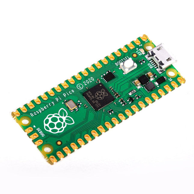
Raspberry Pi Foundation Raspberry Pi Pico
Features RP2040 microcontroller chip ontwikkeld door Raspberry Pi in Engeland Dual-core ARM Cortex M0+ processor, met een kloksnelheid tot 133 MHz 264 kB SRAM, en 2 MB on-board Flash geheugen Castellated module maakt solderen direct op draagborden mogelijk USB 1.1 host- en apparaatondersteuning Energiezuinige slaap- en slapende modi Programmering via slepen en neerzetten met behulp van massaopslag via USB 26x multifunctionele GPIO-pinnen 2x SPI, 2x I²C, 2× UART, 3x 12-bit ADC, 16x bestuurbare PWM-kanalen Nauwkeurige klok en timer op de chip Temperatuursensor Versnelde drijvende-kommabibliotheken op de chip 8x programmeerbare IO (PIO) toestandsmachines voor aangepaste randapparatuur Waarom een Raspberry Pi Pico? Zelf een microcontroller designen in plaats van een bestaande aanschaffen brengt een aantal voordelen met zich mee. Volgens Raspberry Pi zelf komt niet een van de bestaande beschikbare producten hiervoor in de buurt van hun prijs/performance verhouding. Deze Raspberry Pi Pico heeft Raspberry Pi tevens de mogelijkheid gegeven om zelf een aantal innovatieve en krachtige features toe te voegen. Deze features zijn nergens anders beschikbaar. Een derde reden is dat de Raspberry Pi Pico de mogelijkheid aan Raspberry Pi heeft gegeven om krachtige software rondom het product te creëren. Rondom deze software stack zit een uitgebreide documentatie set. De software en documentatie voldoen aan de hoge standaard van de kernproducten van Raspberry Pi (zoals de Raspberry Pi 400, Pi 4 Model B en Pi 3 Model A+). Voor wie is deze microcontroller geschikt? De Raspberry Pi Pico is voor zowel de gevorderde als beginnende gebruiker geschikt. Van het bedienen van een lichtscherm tot het bedienen van veel verschillende apparaten die je dagelijks gebruikt. Veel dagelijkse bewerkingen worden door deze technologie mogelijk gemaakt. Beginnende gebruikers De Raspberry Pi Pico is programmeerbaar in de talen C en MicroPython en aanpasbaar voor een breed scala aan apparaten. Daarnaast is de Pico net zo eenvoudig in gebruik als het slepen en neerzetten van bestanden. Dit maakt deze microcontroller bij uitstek geschikt voor de beginnende gebruiker. Gevorderde gebruikers Voor de gevorderde gebruikers is het mogelijk om gebruik te maken van de uitgebreide randapparatuur van de Pico. De randapparatuur bestaat onder andere uit de SPI, I²C en acht programmeerbare I/O (PIO) -toestandsmachines. Wat is uniek aan de Raspberry Pi Pico? Uniek aan de Pico is dat deze is ontwikkeld door Raspberry Pi zelf. De RP2040 is voorzien van een dual-core Arm Cortex-M0 + processor met 264 KB intern RAM en ondersteuning voor maximaal 16 MB off-chip Flash. De Raspberry Pi Pico is verder uniek om verschillende redenen: Het product heeft de hoogste prijs/kwaliteit verhouding in de markt van de microcontrollerboards De Raspberry Pi Pico is door Raspberry Pi zelf ontwikkeld De software stack rondom dit product is van hoogwaardige kwaliteit en komt in combinatie met een uitgebreide documentatie set.
-
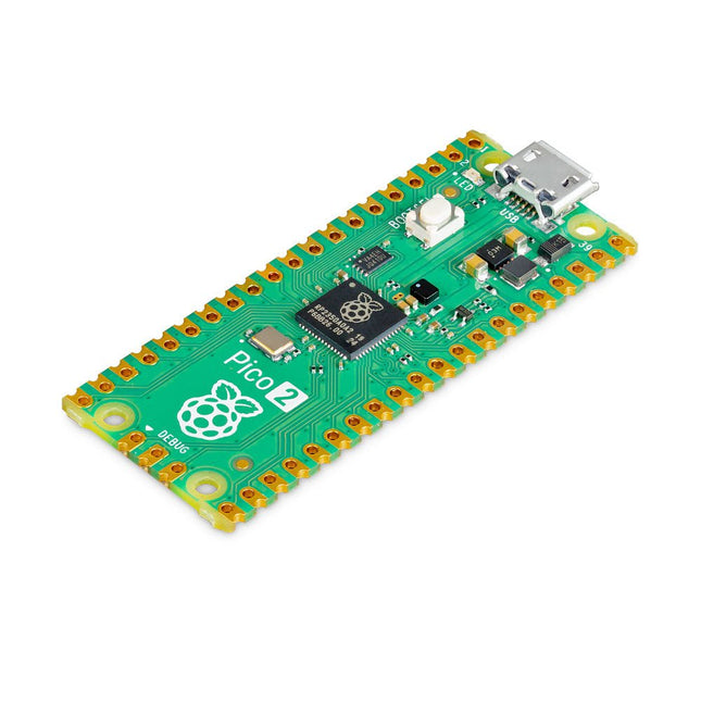
Raspberry Pi Foundation Raspberry Pi Pico 2
De Raspberry Pi Pico 2 is een nieuw microcontrollerbord van de Raspberry Pi Foundation, gebaseerd op de RP2350. Het beschikt over een hogere kloksnelheid, het dubbele van de on-chip SRAM, het dubbele van het ingebouwde flashgeheugen, krachtigere Arm-cores, optionele RISC-V-cores, nieuwe beveiligingsfuncties en verbeterde interfacemogelijkheden. De Raspberry Pi Pico 2 biedt een aanzienlijke verbetering in prestaties en functies, terwijl de hardware- en softwarecompatibiliteit met eerdere leden van de Raspberry Pi Pico-serie behouden blijft. De RP2350 biedt een uitgebreide beveiligingsarchitectuur gebouwd rond Arm TrustZone voor Cortex-M. Het bevat ondertekend opstarten, 8 KB antifuse OTP voor sleutelopslag, SHA-256-versnelling, een hardware TRNG en snelle glitch-detectoren. Dankzij de unieke dual-core en dual-architectuurmogelijkheden van de RP2350 kunnen gebruikers kiezen tussen een paar industriestandaard Arm Cortex-M33-kernen en een paar open-hardware Hazard3 RISC-V-kernen. Programmeerbaar in C/C++ en Python, en ondersteund door gedetailleerde documentatie, is de Raspberry Pi Pico 2 het ideale microcontrollerbord voor zowel liefhebbers als professionele ontwikkelaars. Specificaties CPU Dual Arm Cortex-M33 of dubbele RISC-V Hazard3-processors @ 150 MHz Geheugen 520 KB SRAM op de chip; 4 MB ingebouwde QSPI-flitser Interfaces 26 multifunctionele GPIO-pinnen, waaronder 4 die kunnen worden gebruikt voor AD Randapparatuur 2x UART 2x SPI-controllers 2x I²C-controllers 24x PWM-kanalen 1x USB 1.1-controller en PHY, met host- en apparaatondersteuning 12x PIO-statusmachines Ingangsvermogen 1,8-5,5 V DC Afmetingen 21 x 51 mm Downloads Datasheet (Pico 2) Datasheet (RP2350)
€ 5,95
Leden identiek
-

Raspberry Pi Foundation Raspberry Pi Pico 2 H
De Raspberry Pi Pico 2 H (met headers) is een nieuw microcontrollerbord van de Raspberry Pi Foundation, gebaseerd op de RP2350. Het beschikt over een hogere kloksnelheid, het dubbele van de on-chip SRAM, het dubbele van het ingebouwde flashgeheugen, krachtigere Arm-cores, optionele RISC-V-cores, nieuwe beveiligingsfuncties en verbeterde interfacemogelijkheden. De Raspberry Pi Pico 2 H biedt een aanzienlijke verbetering in prestaties en functies, terwijl de hardware- en softwarecompatibiliteit met eerdere leden van de Raspberry Pi Pico-serie behouden blijft. De RP2350 biedt een uitgebreide beveiligingsarchitectuur gebouwd rond Arm TrustZone voor Cortex-M. Het bevat ondertekend opstarten, 8 KB antifuse OTP voor sleutelopslag, SHA-256-versnelling, een hardware TRNG en snelle glitch-detectoren. Dankzij de unieke dual-core en dual-architectuurmogelijkheden van de RP2350 kunnen gebruikers kiezen tussen een paar industriestandaard Arm Cortex-M33-kernen en een paar open-hardware Hazard3 RISC-V-kernen. Programmeerbaar in C/C++ en Python, en ondersteund door gedetailleerde documentatie, is de Raspberry Pi Pico 2 het ideale microcontrollerbord voor zowel liefhebbers als professionele ontwikkelaars. Specificaties CPU Dual Arm Cortex-M33 of dubbele RISC-V Hazard3-processors @ 150 MHz Geheugen 520 KB SRAM op de chip; 4 MB ingebouwde QSPI-flitser Interfaces 26 multifunctionele GPIO-pinnen, waaronder 4 die kunnen worden gebruikt voor AD Randapparatuur 2x UART 2x SPI-controllers 2x I²C-controllers 24x PWM-kanalen 1x USB 1.1-controller en PHY, met host- en apparaatondersteuning 12x PIO-statusmachines Ingangsvermogen 1,8-5,5 V DC Afmetingen 21 x 51 mm Downloads Datasheet (Pico 2) Datasheet (RP2350)
€ 6,95€ 3,50
Leden identiek
-
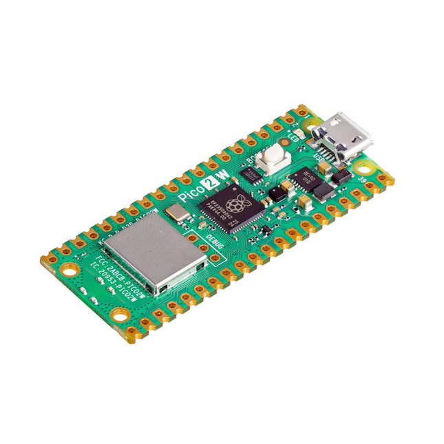
Raspberry Pi Foundation Raspberry Pi Pico 2 W
De Raspberry Pi Pico 2 W is een microcontrollerbord gebaseerd op de RP2350 met 2,4 GHz 802.11n wireless LAN en Bluetooth 5.2. Het geeft u nog meer flexibiliteit in uw IoT- of slimme productontwerpen en breidt de mogelijkheden voor uw projecten uit. De RP2350 biedt een uitgebreide beveiligingsarchitectuur gebouwd rond Arm TrustZone voor Cortex-M. Het bevat ondertekend opstarten, 8 KB antifuse OTP voor sleutelopslag, SHA-256-versnelling, een hardware TRNG en snelle glitch-detectoren. Dankzij de unieke dual-core en dual-architectuurmogelijkheden van de RP2350 kunnen gebruikers kiezen tussen een paar industriestandaard Arm Cortex-M33-kernen en een paar open-hardware Hazard3 RISC-V-kernen. Programmeerbaar in C/C++ en Python, en ondersteund door gedetailleerde documentatie, is de Raspberry Pi Pico 2 W het ideale microcontrollerbord voor zowel liefhebbers als professionele ontwikkelaars. Specificaties CPU Dual Arm Cortex-M33 of dubbele RISC-V Hazard3-processors @ 150 MHz Wireless Geïntegreerde Infineon CYW43439 single-band 2,4 GHz 802.11n wireless LAN en Bluetooth 5.2 Geheugen 520 KB SRAM op de chip; 4 MB ingebouwde QSPI-flitser Interfaces 26 multifunctionele GPIO-pinnen, waaronder 4 die kunnen worden gebruikt voor AD Randapparatuur 2x UART 2x SPI-controllers 2x I²C-controllers 24x PWM-kanalen 1x USB 1.1-controller en PHY, met host- en apparaatondersteuning 12x PIO-statusmachines Ingangsvermogen 1,8-5,5 V DC Afmetingen 21 x 51 mm Downloads Datasheet Pinout Schematic
€ 7,95
Leden identiek
-
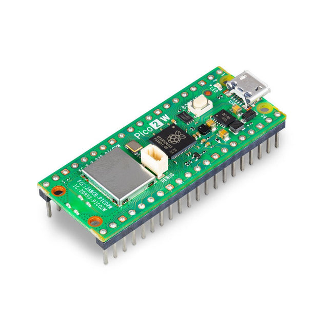
Raspberry Pi Foundation Raspberry Pi Pico 2 WH
De Raspberry Pi Pico 2 WH (met headers) is een microcontrollerbord gebaseerd op de RP2350 met 2,4 GHz 802.11n wireless LAN en Bluetooth 5.2. Het geeft u nog meer flexibiliteit in uw IoT- of slimme productontwerpen en breidt de mogelijkheden voor uw projecten uit. De RP2350 biedt een uitgebreide beveiligingsarchitectuur gebouwd rond Arm TrustZone voor Cortex-M. Het bevat ondertekend opstarten, 8 KB antifuse OTP voor sleutelopslag, SHA-256-versnelling, een hardware TRNG en snelle glitch-detectoren. Dankzij de unieke dual-core en dual-architectuurmogelijkheden van de RP2350 kunnen gebruikers kiezen tussen een paar industriestandaard Arm Cortex-M33-kernen en een paar open-hardware Hazard3 RISC-V-kernen. Programmeerbaar in C/C++ en Python, en ondersteund door gedetailleerde documentatie, is de Raspberry Pi Pico 2 WH het ideale microcontrollerbord voor zowel liefhebbers als professionele ontwikkelaars. Specificaties CPU Dual Arm Cortex-M33 of dubbele RISC-V Hazard3-processors @ 150 MHz Wireless Geïntegreerde Infineon CYW43439 single-band 2,4 GHz 802.11n wireless LAN en Bluetooth 5.2 Geheugen 520 KB SRAM op de chip; 4 MB ingebouwde QSPI-flitser Interfaces 26 multifunctionele GPIO-pinnen, waaronder 4 die kunnen worden gebruikt voor AD Randapparatuur 2x UART 2x SPI-controllers 2x I²C-controllers 24x PWM-kanalen 1x USB 1.1-controller en PHY, met host- en apparaatondersteuning 12x PIO-statusmachines Ingangsvermogen 1,8-5,5 V DC Afmetingen 21 x 51 mm Downloads Datasheet Pinout Schematic
€ 8,95€ 4,50
Leden identiek
-
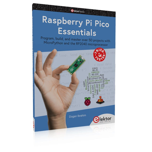
Elektor Publishing Raspberry Pi Pico Essentials
De Raspberry Pi Pico is een krachtige microcontrollermodule die speciaal ontworpen is voor fysiek computergebruik. Microcontrollers verschillen van single-board computers, zoals de Raspberry Pi 4, doordat ze geen besturingssysteem hebben. De Raspberry Pi Pico kan geprogrammeerd worden om een enkele taak zeer efficiënt uit te voeren binnen real-time regel- en besturingstoepassingen die snelheid vereisen. De 'Pico', zoals we hem noemen, is gebaseerd op de snelle, efficiënte en goedkope dual-core ARM Cortex-M0+ RP2040 microcontroller chip die tot 133 MHz werkt en beschikt over 264 KB SRAM, en 2 MB Flash geheugen. Behalve het grote geheugen heeft de Pico nog meer aantrekkelijke eigenschappen, waaronder een groot aantal GPIO pinnen, en populaire interface modules zoals ADC, SPI, I²C, UART, en PWM. Als klap op de vuurpijl biedt de chip snelle en nauwkeurige timing modules, een hardware debug interface, en een interne temperatuursensor.De Raspberry Pi Pico is gemakkelijk te programmeren met populaire talen op hoog niveau, zoals MicroPython en of C/C++. Dit boek is een inleiding tot het gebruik van de Raspberry Pi Pico microcontroller in combinatie met de programmeertaal MicroPython. De Thonny ontwikkelomgeving (IDE) wordt in alle beschreven projecten gebruikt. Er staan meer dan 50 werkende en geteste projecten in het boek, die de volgende onderwerpen behandelen: MicroPython installeren op Raspberry Pi Pico met behulp van een Raspberry Pi of een PC Timer interrupts en externe interrupts Analoog/Digitaal Converter (ADC) projecten Gebruik van de interne temperatuursensor en externe temperatuursensor chips Datalogging projecten PWM, UART, I²C, en SPI projecten Wi-Fi en apps gebruiken om met smartphones te communiceren Bluetooth en apps gebruiken om met smartphones te communiceren Digitaal/Analoog Converter (DAC) projecten Alle projecten die in het boek vermeld worden zijn volledig getest en werken. Alleen basis ervaring met programmeren en elektronica is nodig om de projecten te volgen. Voor alle beschreven projecten worden korte beschrijvingen, blokschema's, gedetailleerde schakelschema's, en volledige MicroPython programma-overzichten gegeven. Lezers kunnen de programma-overzichten vinden op de Elektor webpagina die ter ondersteuning van het boek werd gemaakt.
€ 39,95
Leden € 35,96
-
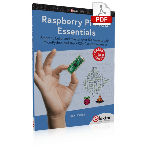
Elektor Digital Raspberry Pi Pico Essentials (E-book)
Program, build, and master over 50 projects with MicroPython and the RP2040 microprocessor The Raspberry Pi Pico is a high-performance microcontroller module designed especially for physical computing. Microcontrollers differ from single-board computers, like the Raspberry Pi 4, in not having an operating system. The Raspberry Pi Pico can be programmed to run a single task very efficiently within real-time control and monitoring applications requiring speed. The ‘Pico’ as we call it, is based on the fast, efficient, and low-cost dual-core ARM Cortex-M0+ RP2040 microcontroller chip running at up to 133 MHz and sporting 264 KB of SRAM, and 2 MB of Flash memory. Besides its large memory, the Pico has even more attractive features including a vast number of GPIO pins, and popular interface modules like ADC, SPI, I²C, UART, and PWM. To cap it all, the chip offers fast and accurate timing modules, a hardware debug interface, and an internal temperature sensor. The Raspberry Pi Pico is easily programmed using popular high-level languages such as MicroPython and or C/C++. This book is an introduction to using the Raspberry Pi Pico microcontroller in conjunction with the MicroPython programming language. The Thonny development environment (IDE) is used in all the projects described. There are over 50 working and tested projects in the book, covering the following topics: Installing the MicroPython on Raspberry Pi Pico using a Raspberry Pi or a PC Timer interrupts and external interrupts Analogue-to-digital converter (ADC) projects Using the internal temperature sensor and external temperature sensor chips Datalogging projects PWM, UART, I²C, and SPI projects Using Wi-Fi and apps to communicate with smartphones Using Bluetooth and apps to communicate with smartphones Digital-to-analogue converter (DAC) projects All projects given in the book have been fully tested and are working. Only basic programming and electronics experience is required to follow the projects. Brief descriptions, block diagrams, detailed circuit diagrams, and full MicroPython program listings are given for all projects described. Readers can find the program listings on the Elektor web page created to support the book.
€ 32,95
Leden € 26,36
-
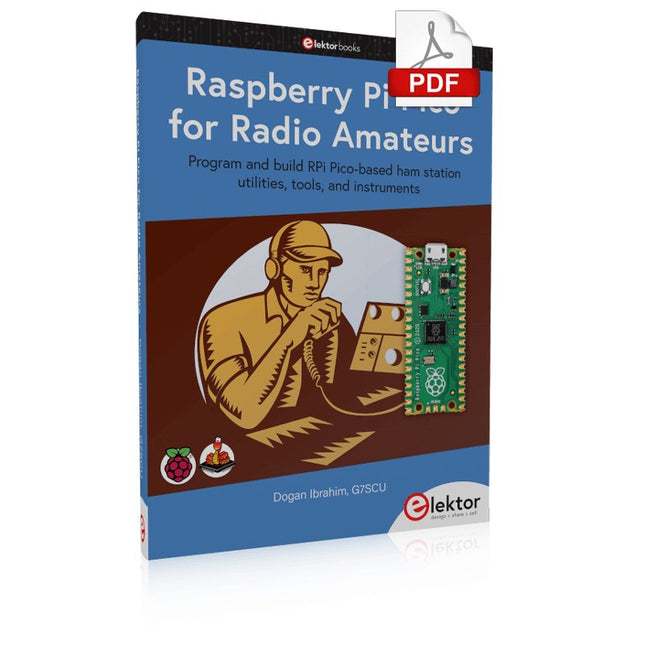
Elektor Digital Raspberry Pi Pico for Radio Amateurs (E-book)
Program and build RPi Pico-based ham station utilities, tools, and instruments Although much classical HF and mobile equipment is still in use by large numbers of amateurs, the use of computers and digital techniques has now become very popular among amateur radio operators. Nowadays, anyone can purchase a €5 Raspberry Pi Pico microcontroller board and develop many amateur radio projects using the “Pico” and some external components. This book is aimed at amateur radio enthusiasts, Electronic Engineering students, and anyone interested in learning to use the Raspberry Pi Pico to shape their electronic projects. The book is suitable for beginners in electronics as well as for those with wide experience. Step-by-step installation of the MicroPython programming environment is described. Some knowledge of the Python programming language is helpful to be able to comprehend and modify the projects given in the book. The book introduces the Raspberry Pi Pico and gives examples of many general-purpose, software-only projects that familiarize the reader with the Python programming language. In addition to the software-only projects tailored to the amateur radio operator, Chapter 6 in particular presents over 36 hardware-based projects for “hams”, including: Station mains power on/off control Radio station clock GPS based station geographical coordinates Radio station temperature and humidity Various waveform generation methods using software and hardware (DDS) Frequency counter Voltmeter / ammeter / ohmmeter / capacitance meter RF meter and RF attenuators Morse code exercisers RadioStation Click board Raspberry Pi Pico based FM radio Using Bluetooth and Wi-Fi with Raspberry Pi Pico Radio station security with RFID Audio amplifier module with rotary encoder volume control Morse decoder Using the FS1000A TX-RX modules to communicate with Arduino
€ 32,95
Leden € 26,36
-
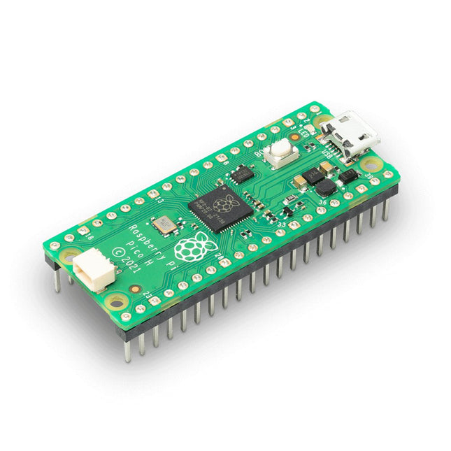
Raspberry Pi Foundation Raspberry Pi Pico H
Raspberry Pi Pico is een goedkoop, hoogwaardig microcontrollerboard en tevens het eerste product op basis van een door Raspberry Pi zelf ontwikkelde chip. De RP2040 microcontrollerchip ('Raspberry Silicon') biedt een dual-core ARM Cortex-M0+ processor (133 MHz), 256 KB RAM, 30 GPIO-pennen en vele andere interface-opties. Daarnaast is er 2 MB on-board QSPI-flashgeheugen voor code- en gegevensopslag. Features RP2040 microcontroller chip ontwikkeld door Raspberry Pi in Engeland Dual-core ARM Cortex M0+ processor, met een kloksnelheid tot 133 MHz 264 kB SRAM, en 2 MB on-board Flash geheugen Castellated module maakt solderen direct op draagborden mogelijk USB 1.1 host- en apparaatondersteuning Energiezuinige slaap- en slapende modi Programmering via slepen en neerzetten met behulp van massaopslag via USB 26x multifunctionele GPIO-pinnen 2x SPI, 2x I²C, 2× UART, 3x 12-bit ADC, 16x bestuurbare PWM-kanalen Nauwkeurige klok en timer op de chip Temperatuursensor Versnelde drijvende-kommabibliotheken op de chip 8x programmeerbare IO (PIO) toestandsmachines voor aangepaste randapparatuur H-versie van de Raspberry Pi Pico met gesoldeerde pin headers en 3-pin debug connector Downloads Specifications of 3-pin Debig Connector
-
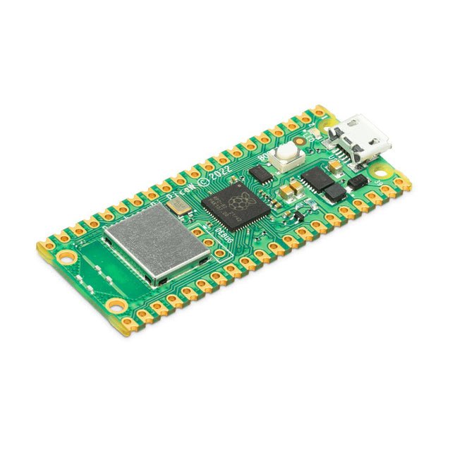
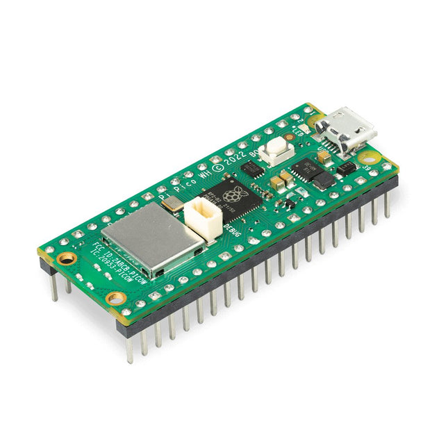
Raspberry Pi Foundation Raspberry Pi Pico W
De Raspberry Pi Pico W is een microcontroller board gebaseerd op de Raspberry Pi RP2040 microcontroller chip. De RP2040-microcontrollerchip ('Raspberry Silicon') heeft een dual-core ARM Cortex-M0+ processor (133 MHz), 256 KB RAM, 30 GPIO-pinnen, en nog vele andere interface opties. Daarnaast is er 2 MB on-board QSPI-flashgeheugen voor code- en gegevensopslag. De Raspberry Pi Pico W is ontworpen als een goedkoop maar flexibel ontwikkelingsplatform voor de RP2040, met een 2,4 GHz draadloze interface met de Infineon CYW43439. De draadloze interface is via SPI aangesloten op de RP2040. Kenmerken van de Pico W RP2040 microcontroller met 2 MB flashgeheugen On-board single-band 2,4 GHz draadloze interfaces (802.11n) Micro USB B poort voor voeding en data (en voor het herprogrammeren van de flash) 40 pin 21 x 51 mm 'DIP' stijl 1 mm dikke PCB met 0,1' through-hole pinnen met ook gegroefde gaten. Beschikt over 26 multifunctionele 3,3 V I/O voor algemeen gebruik (GPIO) 23 GPIO zijn alleen digitaal, en 3 GPIO die ook geschikt zijn voor ADC Kan als opbouw-module worden gemonteerd 3-pins ARM serial wire debug (SWD) poort Eenvoudige maar zeer flexibele mogelijkheden voor de voeding: Verschillende opties om het apparaat eenvoudig van stroom te voorzien via micro-USB, externe voedingen of batterijen Hoge kwaliteit, lage kosten, hoge beschikbaarheid Uitgebreide SDK, voorbeeldsoftware en documentatie Kenmerken van de RP2040 microcontroller Dual-core cortex M0+ tot maximaal 133 MHz On-chip PLL maakt variabele core-frequentie mogelijk 264 kByte multi-bank SRAM met hoge prestaties Externe Quad-SPI Flash met eXecute In Place (XIP) en 16 kByte on-chip cache Hoogwaardige full-crossbar bus architecture Ingebouwde USB1.1 (device of host) 30 multifunctionele algemene I/O (vier kunnen worden gebruikt voor ADC) 1,8-3,3 V I/O-spanning 12-bits 500 ksps analoog naar digitaal converter (ADC) Diverse digitale randapparatuur 2x UART, 2x I²C, 2x SPI, 16x PWM kanalen 1x timer met 4 alarmen, 1x real time clock 2x programmeerbare I/O (PIO) blokken, 8 state machines in totaal Flexibele, door de gebruiker programmeerbare high-speed I/O Kan interfaces zoals SD-kaart en VGA emuleren Note: De Raspberry Pi Pico W I/O-spanning is 3,3 V. Downloads Datasheet Specifications of 3-pin Debug Connector
€ 7,95
Leden identiek
-
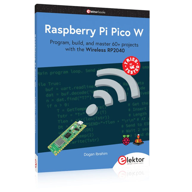
Elektor Publishing Raspberry Pi Pico W (Book)
Program, build, and master 60+ projects with the Wireless RP2040 The Raspberry Pi Pico and Pico W are based on the fast, efficient, and low-cost dual-core ARM Cortex M0+ RP2040 microcontroller chip running at up to 133 MHz and sporting 264 KB of SRAM and 2 MB of Flash memory. Besides spacious memory, the Pico and Pico W offer many GPIO pins, and popular peripheral interface modules like ADC, SPI, I²C, UART, PWM, timing modules, a hardware debug interface, and an internal temperature sensor. The Raspberry Pi Pico W additionally includes an on-board Infineon CYW43439 Bluetooth and Wi-Fi chipset. At the time of writing this book, the Bluetooth firmware was not yet available. Wi-Fi is however fully supported at 2.4 GHz using the 802.11b/g/n protocols. This book is an introduction to using the Raspberry Pi Pico W in conjunction with the MicroPython programming language. The Thonny development environment (IDE) is used in all of the 60+ working and tested projects covering the following topics: Installing the MicroPython on Raspberry Pi Pico using a Raspberry Pi or a PC Timer interrupts and external interrupts Analogue-to-digital converter (ADC) projects Using the internal temperature sensor and external sensor chips Using the internal temperature sensor and external temperature sensor chips Datalogging projects PWM, UART, I²C, and SPI projects Using Bluetooth, WiFi, and apps to communicate with smartphones Digital-to-analogue converter (DAC) projects All projects are tried & tested. They can be implemented on both the Raspberry Pi Pico and Raspberry Pi Pico W, although the Wi-Fi-based subjects will run on the Pico W only. Basic programming and electronics experience are required to follow the projects. Brief descriptions, block diagrams, detailed circuit diagrams, and full MicroPython program listings are given for all projects.
€ 44,95
Leden identiek
-

Elektor Digital Raspberry Pi Pico W (E-book)
Program, build, and master 60+ projects with the Wireless RP2040 The Raspberry Pi Pico and Pico W are based on the fast, efficient, and low-cost dual-core ARM Cortex M0+ RP2040 microcontroller chip running at up to 133 MHz and sporting 264 KB of SRAM and 2 MB of Flash memory. Besides spacious memory, the Pico and Pico W offer many GPIO pins, and popular peripheral interface modules like ADC, SPI, I²C, UART, PWM, timing modules, a hardware debug interface, and an internal temperature sensor. The Raspberry Pi Pico W additionally includes an on-board Infineon CYW43439 Bluetooth and Wi-Fi chipset. At the time of writing this book, the Bluetooth firmware was not yet available. Wi-Fi is however fully supported at 2.4 GHz using the 802.11b/g/n protocols. This book is an introduction to using the Raspberry Pi Pico W in conjunction with the MicroPython programming language. The Thonny development environment (IDE) is used in all of the 60+ working and tested projects covering the following topics: Installing the MicroPython on Raspberry Pi Pico using a Raspberry Pi or a PC Timer interrupts and external interrupts Analogue-to-digital converter (ADC) projects Using the internal temperature sensor and external sensor chips Using the internal temperature sensor and external temperature sensor chips Datalogging projects PWM, UART, I²C, and SPI projects Using Bluetooth, WiFi, and apps to communicate with smartphones Digital-to-analogue converter (DAC) projects All projects are tried & tested. They can be implemented on both the Raspberry Pi Pico and Raspberry Pi Pico W, although the Wi-Fi-based subjects will run on the Pico W only. Basic programming and electronics experience are required to follow the projects. Brief descriptions, block diagrams, detailed circuit diagrams, and full MicroPython program listings are given for all projects.
€ 34,95
Leden € 27,96
-
Elektor Publishing Raspberry Pi Pico W en un tournemain
Maîtrise de la puce RP2040 avec plus de 60 projets à réaliser et à programmer Les cartes Raspberry Pi Pico et Pico W sont animées par un microcontrôleur ARM Cortex M0+ RP2040 à double coeur, rapide, efficace et peu coûteux, qui fonctionne jusqu'à 133 MHz et dispose de 264 Ko de SRAM et de 2 Mo de mémoire Flash. Outre une vaste mémoire, le Pico et le Pico W disposent de nombreuses broches GPIO et d'interfaces telles que CA/N, SPI, I²C, UART, MLI, de fonctions de temporisation, d'une interface de débogage matériel et d'un capteur de température interne. La carte Raspberry Pi Pico W comporte en plus une puce CYW43439 Bluetooth et Wi-Fi d'Infineon. Au moment de la rédaction de ce livre, le micrologiciel Bluetooth pour le Pico W n'était pas encore disponible. Le Wi-Fi à 2,4 GHz est toutefois entièrement pris en charge avec les protocoles 802.11b/g/n. Ce livre est une introduction à l'utilisation du Raspberry Pi Pico W avec le langage de programmation MicroPython. Les quelque soixante projets testés et opérationnels sont présentés à l'aide de l'environnement de développement intégré (EDI) Thonny. Les sujets abordés sont nombreux : Installation de MicroPython sur le Raspberry Pi Pico depuis un PC Interruptions de l'horloge et interruptions externes Convertisseur analogique-numérique (CA/N) Capteurs de température interne et externe Capteurs externes (pression, humidité, pouls, à ultrasons) Enregistrement de données MLI, UART, I²C et SPI Bluetooth, Wi-Fi et applis sur smarphone Convertisseur numérique-analogique (CN/A) Tous les projets ont été testés et éprouvés. Ils peuvent être mis en oeuvre sur le Raspberry Pi Pico ainsi que sur le Raspberry Pi Pico W. Toutefois les projets avec une liaison Wi-Fi ne fonctionnent que sur le Pico W. Une petite expérience en programmation et en électronique est nécessaire pour suivre les projets. De brèves descriptions, des schémas fonctionnels, des schémas détaillés du câblage des montages et des listings MicroPython complets sont fournis pour tous les projets.
€ 44,95
Leden € 40,46
-
Elektor Digital Raspberry Pi Pico W en un tournemain (PDF)
Maîtrise de la puce RP2040 avec plus de 60 projets à réaliser et à programmer Les cartes Raspberry Pi Pico et Pico W sont animées par un microcontrôleur ARM Cortex M0+ RP2040 à double coeur, rapide, efficace et peu coûteux, qui fonctionne jusqu'à 133 MHz et dispose de 264 Ko de SRAM et de 2 Mo de mémoire Flash. Outre une vaste mémoire, le Pico et le Pico W disposent de nombreuses broches GPIO et d'interfaces telles que CA/N, SPI, I²C, UART, MLI, de fonctions de temporisation, d'une interface de débogage matériel et d'un capteur de température interne. La carte Raspberry Pi Pico W comporte en plus une puce CYW43439 Bluetooth et Wi-Fi d'Infineon. Au moment de la rédaction de ce livre, le micrologiciel Bluetooth pour le Pico W n'était pas encore disponible. Le Wi-Fi à 2,4 GHz est toutefois entièrement pris en charge avec les protocoles 802.11b/g/n. Ce livre est une introduction à l'utilisation du Raspberry Pi Pico W avec le langage de programmation MicroPython. Les quelque soixante projets testés et opérationnels sont présentés à l'aide de l'environnement de développement intégré (EDI) Thonny. Les sujets abordés sont nombreux : Installation de MicroPython sur le Raspberry Pi Pico depuis un PC Interruptions de l'horloge et interruptions externes Convertisseur analogique-numérique (CA/N) Capteurs de température interne et externe Capteurs externes (pression, humidité, pouls, à ultrasons) Enregistrement de données MLI, UART, I²C et SPI Bluetooth, Wi-Fi et applis sur smarphone Convertisseur numérique-analogique (CN/A) Tous les projets ont été testés et éprouvés. Ils peuvent être mis en oeuvre sur le Raspberry Pi Pico ainsi que sur le Raspberry Pi Pico W. Toutefois les projets avec une liaison Wi-Fi ne fonctionnent que sur le Pico W. Une petite expérience en programmation et en électronique est nécessaire pour suivre les projets. De brèves descriptions, des schémas fonctionnels, des schémas détaillés du câblage des montages et des listings MicroPython complets sont fournis pour tous les projets.
€ 34,95
Leden € 27,96
-
Raspberry Pi Foundation Raspberry Pi Pico WH
De Raspberry Pi Pico WH is een microcontroller board gebaseerd op de Raspberry Pi RP2040 microcontroller chip. De RP2040 microcontroller ('Raspberry Silicon') maakt gebruik van een dual-core ARM Cortex-M0 + -processor (133 MHz), 256 KB RAM, 30 GPIO-pinnen en vele andere interface opties. Daarnaast heeft hij 2 MB on-board QSPI flash geheugen voor het opslaan van code en data. De Raspberry Pi Pico WH is ontworpen als een goedkoop maar flexibel ontwikkelplatform voor de RP2040, met een 2.4 GHz draadloze interface die gebruik maakt van een Infineon CYW43439. De draadloze interface is via SPI verbonden met de RP2040. Kenmerken van de Pico WH RP2040 microcontroller met 2 MB flash geheugen On-board single-band 2,4 GHz draadloze interfaces (802.11n) Micro-USB-B poort voor voeding en data (en voor het herprogrammeren van de flash) 40 pins 21 x 51 mm 'DIP' stijl 1 mm dikke PCB met 0,1' through-hole pinnen, met ook castellations aan de rand Beschikt over 26 multifunctionele 3,3 V general purpose I/O (GPIO) poorten 23 hiervan zijn alleen digitaal, waarvan er 3 ook geschikt zijn voor ADC Kan als module op andere bordjes bevestigd worden 3-pins ARM serial wire debug (SWD) poort Eenvoudige maar zeer flexibele mogelijkheden voor de voeding Verschillende opties om het apparaat eenvoudig te voeden via micro-USB, externe voedingen of accu’s Hoge kwaliteit, lage kosten, hoge beschikbaarheid Uitgebreide SDK, software voorbeelden en documentatie Voorgemonteerde headers en een 3-pins debug connector Kenmerken van de RP2040 microcontroller Dual-core cortex M0+ tot 133 MHz On-chip PLL maakt variabele clocking van de core mogelijk 264 kByte multi-bank high performance SRAM Externe Quad-SPI Flash met eXecute In Place (XIP) en 16 kByte on-chip cache Hoogwaardige full-crossbar bus fabric On-board USB1.1 (randapparaat of host) 30 multifunctionele general purpose I/O-poorten (4 kunnen worden gebruikt voor ADC) 1,8-3,3 V I/O-spanning 12-bits 500 ksps analoog naar digitaal converter (ADC) Diverse digitale randapparatuur 2x UART, 2x I²C, 2x SPI, 16x PWM kanalen 1x timer met 4 alarmen, 1x real time clock 2x programmeerbare I/O (PIO) blocks, 8 state machines in totaal Flexibele, door de gebruiker programmeerbare high-speed I/O Kan interfaces zoals een SD-kaart en VGA emuleren Opmerking: De Raspberry Pi Pico W I/O-spanning staat ingesteld op 3,3 V Downloads Datasheet Specificaties van de 3-pins Debug Connector
€ 9,95€ 4,95
Leden identiek
-
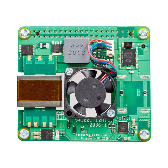
Raspberry Pi Foundation Raspberry Pi PoE+ HAT (voor Raspberry Pi 3 B+ en 4)
De Raspberry Pi PoE+ HAT is een add-on board ontworpen voor Raspberry Pi 3 B+ en Raspberry Pi 4 uitgerust met PoE-pinnen. Het voedt de Raspberry Pi via een Ethernet-kabel, mits er compatibele Power-Sourcing Equipment (PSE) aanwezig is op het Ethernet-netwerk. Daarnaast bevat de HAT een geïntegreerde ventilator om de Raspberry Pi-processor te koelen. Specificaties Standaard IEEE 802.3at-2003 PoE Ingangsspanning 37-57 V DC, apparaat van klasse 4 Uitgangsspanning 5 V DC/4 A Koeling 25 x 25 mm borstelloze ventilator die 2,2 CFM levert voor processorkoeling Bedrijfstemperatuur 0°C tot +50°C Downloads Datasheet
-
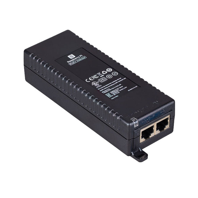
Raspberry Pi Foundation Raspberry Pi PoE+ Injector
De Raspberry Pi PoE+ Injector voegt Power-over-Ethernet (PoE) functionaliteit toe aan een enkele poort van een niet-PoE Ethernet switch, en levert zowel stroom als data via één Ethernet-kabel. Het biedt een plug-and-play, kosteneffectieve oplossing voor het stapsgewijs introduceren van PoE capaciteit in bestaande Ethernet netwerken. De PoE+ Injector is een single-port, 30 W apparaat geschikt voor het voeden van apparatuur die voldoet aan de IEEE 802.3af en 802.3at standaarden, inclusief alle generaties Raspberry Pi PoE HAT's. Het ondersteunt netwerk pass-through snelheden van 10/100/1000 Mbps. Opmerking: Een aparte IEC netsnoer is vereist voor gebruik (niet meegeleverd). Specificaties Gegevenssnelheid 10/100/1000 Mbps Ingangsspanning 100 tot 240 V AC Uitgangsvermogen 30 W Uitgangsvermogen op pinnen 4/5 (+), 7/8 (–) Nominale uitgangsspanning 55 V DC Gegevensconnectoren Afgeschermde RJ-45, EIA 568A en 568B Stroomaansluiting IEC c13 netvoeding (niet meegeleverd) Opslagvochtigheid Maximaal 95%, niet-condenserend Werkingshoogte –300 m tot 3000 m Werkingsomgevingstemperatuur 10°C tot +50°C Afmetingen 159 x 51,8 x 33,5 mm Downloads Datasheet
€ 29,95€ 14,95
Leden identiek
-
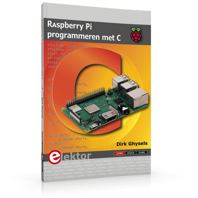
Elektor Publishing Raspberry Pi programmeren met C
Dit boek gaat over de Raspberry Pi, en over het programmeren in C. De programmeertaal C en het besturingssysteem Linux (Raspbian) passen uitstekend bij elkaar. Alles wat we nodig hebben om in C te programmeren wordt meegeleverd met het besturingssysteem van de Raspberry Pi. In dit boek leert u hoe C gebruikt wordt met de Raspberry Pi, en krijgt u een overzicht van de taal. WiringPi is een softwarebibliotheek voor de Raspberry Pi waarmee C hardware-uitbreidingen kan benaderen. Die bibliotheek wordt gebruikt om sensoren uit te lezen en om extra hardware aan te sturen. U gaat experimenteren met LED’s en schakelaars, met motoren, met geluid en met sensoren voor temperatuur, luchtdruk, en luchtvochtigheid. Met een Linux-systeem kunt u een webserver maken, inclusief interactieve websites met PHP en WiringPi. Daarom is ook een beknopt overzicht van HTML en PHP in het boek opgenomen. In de voorbeelden worden sensoren via het web uitgelezen en worden apparaten bestuurd. In het laatste voorbeeld wordt een temperatuurlogger gemaakt. Die meet elk kwartier de temperatuur. Een tabel met de meetwaarden kan via het web worden uitgelezen. Alle voorbeeldprogramma’s kunnen worden gedownload van de website van Elektor.
€ 34,95
Leden € 31,46
-
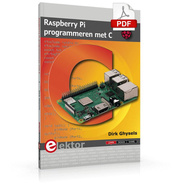
Elektor Digital Raspberry Pi programmeren met C (E-book)
Dit boek gaat over de Raspberry Pi, en over het programmeren in C. De programmeertaal C en het besturingssysteem Linux (Raspbian) passen uitstekend bij elkaar. Alles wat we nodig hebben om in C te programmeren wordt meegeleverd met het besturingssysteem van de Raspberry Pi. In dit boek leert u hoe C gebruikt wordt met de Raspberry Pi, en krijgt u een overzicht van de taal. WiringPi is een softwarebibliotheek voor de Raspberry Pi waarmee C hardware-uitbreidingen kan benaderen. Die bibliotheek wordt gebruikt om sensoren uit te lezen en om extra hardware aan te sturen. U gaat experimenteren met LED’s en schakelaars, met motoren, met geluid en met sensoren voor temperatuur, luchtdruk, en luchtvochtigheid. Met een Linux-systeem kunt u een webserver maken, inclusief interactieve websites met PHP en WiringPi. Daarom is ook een beknopt overzicht van HTML en PHP in het boek opgenomen. In de voorbeelden worden sensoren via het web uitgelezen en worden apparaten bestuurd. In het laatste voorbeeld wordt een temperatuurlogger gemaakt. Die meet elk kwartier de temperatuur. Een tabel met de meetwaarden kan via het web worden uitgelezen. Alle voorbeeldprogramma’s kunnen worden gedownload van de website van Elektor.
€ 29,95
Leden € 23,96
-

Raspberry Pi Foundation Raspberry Pi RP2040 Microcontroller ICs (10 stuks)
Specificaties Dubbele ARM Cortex-M0+ @ 133 MHz 264 kB on-chip SRAM in zes onafhankelijke banken Ondersteuning tot 16 MB off-chip Flash memory via speciale QSPI bus DMA-controller Volledig aangesloten AHB crossbar Interpolator en integer divider peripherals On-chip programmeerbare LDO om spanning voor de core te genereren 2x on-chip PLL's om USB en core kloksignalen te genereren 30x GPIO pins, waarvan er 4 als analoge ingangen kunnen worden gebruikt Randapparatuur 2x UARTs 2x SPI controllers 2x I²C controllers 16x PWM kanalen USB 1.1 controller en PHY, met host en device support 8x PIO state machines Wat je krijgt 10x RP2040 ICs
€ 7,95€ 2,95
Leden identiek
-

Elektor Digital Elektor Select: Raspberry Pi Compilatie (PDF)
Dit 61 pagina's tellende E-Book staat bol van de ideeën, uitleg, tips, diagrammen, programma's, PCB layouts en meer. Genoeg voor informatief, inspirerend en stimulerend leesplezier! Opgemaakt als PDF bevat dit digitale document een inhoudsopgave inclusief links naar elk project, zo dat u gemakkelijk komt waar u wilt zijn. Dit biedt u de mogelijkheid om tussen projecten te wisselen en degene die u het meeste boeien snel en gemakkelijk te vinden. Dit E-Book is uit de serie 'Elektor Select', het nieuwe label van Elektor dat logische series artikelen die in Elektor Magazine gedurende een periode zijn uitgebracht bundelt in één gemakkelijke uitgave. Wij hopen dat u ervan zult genieten. Het Elektor Team
€ 9,50
Leden € 7,60


