Deze bundel bevat de Red Pitaya STEMlab 125-14 PRO Gen 2 Starter Kit en het nieuwe boek "Experimenteren met Red Pitaya STEMlab Gen 2".
De Red Pitaya STEMlab 125-14 PRO Gen 2 Starter Kit is een krachtig en flexibel platform voor signaalverwerking, data-acquisitie en elektronische meettoepassingen. Deze kit is ontworpen voor ingenieurs, ontwikkelaars, onderzoekers en docenten en biedt alles wat nodig is om te beginnen met het bouwen van geavanceerde meet- en besturingssystemen.
De kern van de kit wordt gevormd door het STEMlab 125-14 PRO Gen 2-bord, een geüpgradede en ultralichte ontwikkeling. Aangedreven door de Xilinx Zynq-7010 SoC met 512 MB RAM, combineert het de programmeerbaarheid van een FPGA met de verwerkingskracht van een ARM-processor om hoogwaardige instrumentatie en aangepaste signaalverwerkingsoplossingen mogelijk te maken.
Het bord biedt een 14-bits ADC- en DAC-resolutie, een bemonsteringsfrequentie van 125 MS/s, een ingangsbereik van ±20 V en een bandbreedte tot 60 MHz. Dankzij de verbeterde ruisarme analoge front-end, USB-C-connectiviteit en het compacte ontwerp is het geschikt voor veeleisende toepassingen zoals RF-ontwikkeling, radarsystemen, fotonica-onderzoek, softwaregedefinieerde radio (SDR) en industriële automatisering.
De Starter Kit bevat alle essentiële accessoires voor onmiddellijk gebruik: een microSD-kaart met vooraf geïnstalleerd besturingssysteem, voeding, ethernetkabel voor toegang op afstand, twee 100 MHz-oscilloscoopprobes en SMA-naar-BNC-adapters voor flexibele signaalaansluitingen.
De Red Pitaya STEMlab 125-14 PRO Gen 2 Starter Kit is een uitstekend platform voor rapid prototyping, FPGA-ontwikkeling, meetinstrumentatie en geavanceerde elektronica-experimenten.
Kenmerken
14-bits ADC- en DAC-resolutie
125 MS/s samplingfrequentie
±20 V ingangsbereik
Tot 60 MHz bandbreedte
Xilinx Zynq-7010 SoC (FPGA + ARM-processor)
512 MB RAM
Ruisarme analoge front- en back-ends
Toepassingen
RF-ontwikkeling en -testen
Radar- en draadloze systemen
Software Defined Radio (SDR)
Fotonica en optisch onderzoek
Industriële automatisering en besturingssystemen
Signaalanalyse en instrumentatie
Snel prototypen van elektronische meetsystemen
Specificaties
Processor
Dual-core ARM Cortex-A9
FPGA
AMD Xilinx Zynq-7010 SoC
RAM
512 MB (4 Gb)
Opslag
microSD-kaart (tot 32 GB)
Besturingssysteem
Linux-gebaseerd Red Pitaya OS
ADC-resolutie
14-bits
DAC Resolutie
14-bits
Bandbreedte
60 MHz (DC)
Sampling rate
125 MS/s
Analoge ingangskanalen
2
Analoge uitgangskanalen
2
Ingangsspanningsbereik
±1 V (LV) / ±20 V (HV)
Ingangsimpedantie
1 MΩ / 10 pF
Uitgangsspanningsbereik
±1 V
Ethernet
1x Gigabit Ethernet (RJ45)
USB
2x USB-C 2.0 (voor voeding en console)
Digitale I/O
16x GPIO (3,3 V)
Communicatie-interfaces
I²C, SPI, UART, CAN
Voeding
5 V/3 A via USB-C
Afmetingen
106,8 x 60,0 x 17,9 mm
Inbegrepen
1x Red Pitaya STEMlab 125-14 PRO Gen 2 Board
2x 100 MHz oscilloscoopprobes
2x SMA-naar-BNC-adapters
1x microSD-kaart met voorgeïnstalleerd besturingssysteem
1x USB-C-voeding
1x Ethernetkabel
Downloads
Documentation
Schematics
Book: Experimenting with Red Pitaya STEMlab Gen 2
Met dit nieuwe boek gaat Red Pitaya verder dan een veelzijdig board. Het wordt een krachtig laboratoriuminstrument voor nauwkeurige metingen, analyse en besturing.
Van de basisprincipes van elektronische projectontwikkeling, monitoring, besturing en ontwerp tot testen: dit boek begeleidt u stap voor stap door alles wat u moet weten om het volledige potentieel van de Red Pitaya-hardware en -software te benutten.
Het boek presenteert real-time, FPGA-gebaseerde projecten die op een PC worden ontwikkeld met de Vivado-omgeving en vervolgens naar de Red Pitaya worden overgebracht voor uitvoering en testen.
U leert over verbeterde prestaties, uitgebreide I/O-mogelijkheden, verbeterde FPGA-functionaliteiten en geavanceerde connectiviteitsopties die nieuwe mogelijkheden openen voor nauwkeurige metingen, monitoring en besturing in uw embedded toepassingen.
In dit boek ontdekt u:
Een diepgaande verkenning van de Red Pitaya-architectuur en het hardwareontwerp
Elektronische experimenten met Red Pitaya voor meting en monitoring
Praktische projecten met de programmeertaal Python
Praktische richtlijnen voor FPGA-programmering met Red Pitaya
Red Pitaya FPGA-projecten met Verilog HDL in de Vivado IDE
Praktisch ontwerp van elektronische projecten inclusief meting en testen
Stapsgewijze voorbeelden die theorie en praktijk met elkaar verbinden
Of u nu uw eigen elektronische schakelingen ontwerpt, tools voor signaalanalyse ontwikkelt of real-time besturings- of monitoringssystemen creëert, dit boek biedt u de kennis en het vertrouwen om het Red Pitaya-platform volledig te leren kennen en aan te passen.
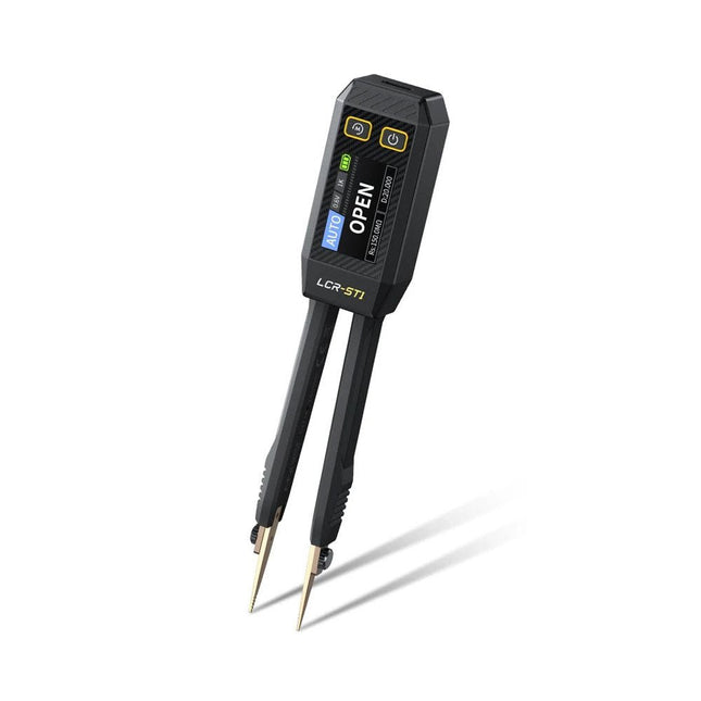
De FNIRSI LCR-ST1 is een compacte, multifunctionele en intelligente LCR-tester die automatische metingen van weerstand, capaciteit, inductantie, diodetests en continuïteit ondersteunt.
Het 1,14-inch kleurendisplay in combinatie met een handige magnetische adsorptiefunctie verbetert het gebruiksgemak, terwijl de ingebouwde lithiumbatterij van 250 mAh langdurige prestaties garandeert. Het apparaat ondersteunt drie frequentiebereiken (100 Hz, 1 kHz en 10 kHz) en biedt 0,3 V en 0,6 V RMS-testniveaus voor veelzijdige testtoepassingen.
Het unieke pincetvormige ontwerp van de LCR-ST1 is ideaal voor delicate taken in kleine ruimtes en maakt het snel en nauwkeurig testen van elektronische componenten mogelijk. Het lichte gewicht en het draagbare ontwerp maken het tot een hulpmiddel van onschatbare waarde voor zowel veld- als laboratoriumgebruik.
Of u nu een ervaren ingenieur bent of net begint in de elektronica, de LCR-ST1 levert betrouwbare en nauwkeurige meetresultaten, waardoor u uw taken efficiënter en nauwkeuriger kunt uitvoeren.
Kenmerken
Biedt 3 testfrequenties (100 Hz, 1 kHz, 10 kHz) en 2 testspanningsniveaus.
Beschikt over automatische componentidentificatie voor snellere en betrouwbaardere metingen.
1,14-inch kleurendisplay met hoge resolutie voor duidelijke aflezingen.
Ondersteunt automatische gegevensregistratie en -opslag.
De pincetpunten zijn gemaakt van verguld messing voor verbeterde duurzaamheid en geleiding.
Specificaties
Weerstandsbereik
10 mΩ – 10 MΩ
Capaciteitsbereik
1 pF – 22 mF
Inductiebereik
1 μu – 10 H
Diode
Aanspanning 0,7 V
Frequentietest
100 Hz, 1 kHz, 10 kHz
Niveautest
0,3 V, 0,6 V RMS
Parameterweergave
ESR, D-waarde, Q-waarde, Z-waarde, X-waarde
Display
1,14" HD-kleurenscherm
Oplaadinterface
USB-C, 5 V/1 A
Voeding
Ingebouwde lithiumbatterij van 250 mAh
Automatische herkenningsmeting
Ja
Vervangbare pincetkop
Ja
Automatische uitschakeling
Ja
Gegevensopslag
Ja
Geschiedenisrecord
Verbinden met pc om te bekijken en exporteren
Afmetingen
28 x 19 x 150 mm
Gewicht
41 g
Inbegrepen
1x LCR-ST1 SMD-pincet
2x Haakpunten
1x Magnetische patch
1x USB-kabel
1x Opbergtas
1x Manual
Downloads
Manual
Firmware V1.6
Deze LC-meter kit is een eenvoudig te bouwen, leerzaam en vermakelijk doe-het-zelf-project voor het meten van de inductie (L) van spoelen en spoelen, de capaciteit (C) van condensatoren, andere passieve componenten en de frequentie van signalen.
Specificaties
Voeding
USB DC 5 V
Capacitantiemeetbereik van kleine niet-gepolariseerde condensatoren
1 pF~2200 pF
Capacitantiemeetbereik van elektrolytische condensatoren
1 µF~12.000 µF
Inductiemeetbereik
1 µH~1 H
Frequentiemeetbereik
20 Hz~400 kHz
Afmetingen (printplaat)
91 x 80 mm
Afmetingen (behuizing)
106 x 91 x 28 mm
Inbegrepen
Dubbelzijdige printplaat
Alle benodigde componenten incl. montagemateriaal LCD-scherm
Zes voorgesneden transparante acrylplaten
Schroeven en moeren
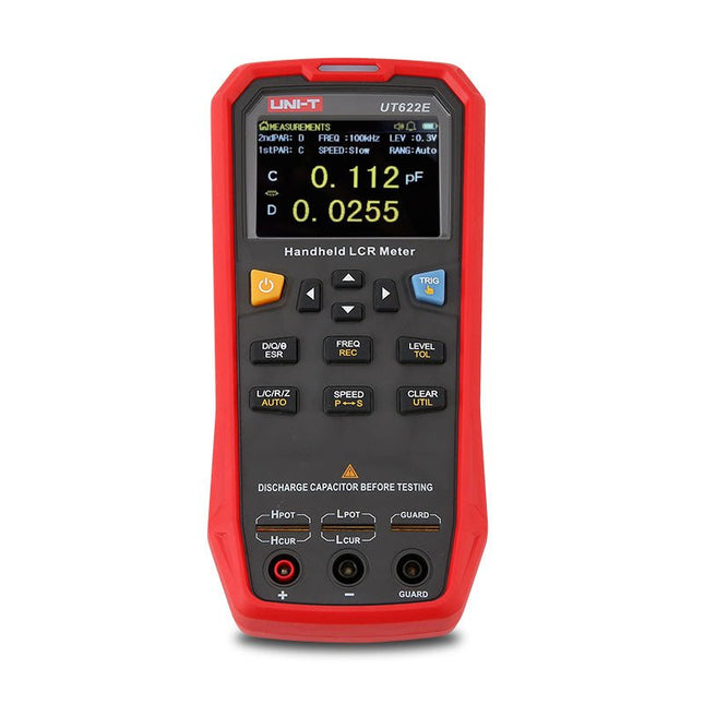
The UT622E handheld LCR meter features powerful functions, high accuracy, fast speed, and long standby time. With a clear and intuitive 2.8-inch TFT LCD display, large-capacity rechargeable battery, and 100 kHz test frequency, the meter can be used for longstanding accurate and convenient measurement in any occasion.
It is suitable for the measurement and screening of inductance, capacitance, and resistance in laboratories, production lines, maintenance points, etc.
Features
Max. test frequency: 100 kHz
Accuracy: 0.1%
Display count: 99999
Max. test rate: 20 times/s
DCR: Yes
Connectivity: Mini-USB
Display: 2.8" TFT LCD
Specifications
Testfrequency
100 Hz, 120 Hz, 1 kHz, 10 kHz, 100 kHz
Test level
0.1 Vmrs, 0.3 Vrms, 1 Vrms
Output impedance
100 Ω
Measurement parameters
Primary: L/C/R/Z/DCRSecondary: D/Q/Θ/ESR
DSR speed test
Fast (20 times/s), medium (5 times/s), or slow (2 times/s)
Range
Auto/Hold
Tolerance range
1%~20%
Equivalent mode
Series/Parallel
Clearing connection
Open/Short circuit
Fuse of test ports
0.1 A/250 V
Communication interface
Mini-USB
MAX reading of primary parameters
99999
MIN resolution
0.0001
Maximum accuracy
0.10%
L
0.00 µH~99.999 H
C
0.00 pF~99.999 mF
Z/R
0.0000 Ω~9.9999 MΩ
ESR
0.0000 Ω~999.99 Ω
D
0.0000~9.9999
Q
0.0000~99999
Θ
-179.9°~179.9°
DCR
0.01 mΩ~20.000 MΩ
Power supply
3.7 V/1800 mAh lithium polymer battery
Display
2.8" TFT LCD (320x240)
Dimensions
93 x 192 x 44 mm
Weight
420 g
Included
UT622E LCR meter
Short circuit board
Four-terminal kelvin test leads
USB cable
Manual
Downloads
Datasheet
Manual
Software
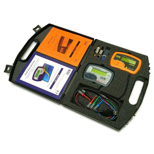
This pack contains the LCR45 Passive Component Impedance Meter, great for advanced hobbyists and professionals. It also contains the very popular DCA Pro (model DCA75), fantastic for component identification, pinout identification, detailed characteristic measurement and curve tracing on a PC. Complete with USB cable and software on a USB flash drive.
DCA75
Building on the continued success of Peak's existing component identification and analysis instruments, the DCA Pro brings an array of exciting new features for the hobbyist and professional alike.
The DCA Pro is an advanced new design that features a graphics display, USB communications, PC Software and an enhanced component identification library.
Automatic component type identification
Automatic pinout identification (connect any way round)
The DCA Pro supports all the components that the popular Peak Atlas DCA55 supports, but adds plenty more. Components supported include:
Transistors (including Darlingtons), Silicon and Germanium types. Measures gain, Vbe and leakage
MOSFETs, enhancement mode and depletion mode types. Measure on-threshold (at 5 mA) and approx transconductance (for span of 3-5 mA)
JFETs, including normally off SiC types. Measures pinch-off voltage (at 1 uA) and approx transconductance (for span of 3-5 mA)
IGBTs (insulated gate bipolar transistors). Measures on-threshold (at 5 mA)
Diodes and Diode networks
LEDs and bicolour LEDs (2 lead and 3 lead types)
Zener Diodes with measurement of zener voltage up to 9 V at 5 mA
Voltage regulators (measures regulation voltage, drop-out voltage, quiescent current)
Triacs and Thyristors that require less than 10 mA of gate current and holding current
Stand-alone or with a PC
The instrument can be used stand-alone or connected to a PC. Either way, the DCA Pro will automatically identify the component type, identify the pinout and also measure a range of component parameters such as transistor gain, leakage, MOSFET and IGBT threshold voltages, pn characteristics and much more.
Curve Tracing
When connected to a PC using the supplied USB cable, a range of low current curve-tracing functions can be performed. Various graph types are available, with more to follow:
Bipolar transistor output characteristics, IC vs VCE
Bipolar transistor gain characteristics, HFE vs VCE
Bipolar transistor gain characteristics, HFE vs IC
MOSFET and IGBT output function, ID vs VDS
MOSFET and IGBT transfer function, ID vs VGS
JFET output function, ID vs VDS
JFET transfer function, ID vs VGS
Voltage regulator, VOUT vs VIN
Voltage regulator, IQ vs VIN.
PN junction I/V curves, forward and reverse options (for Zener diodes)
Curve tracing is performed using test parameters in the range of +/-12 V or +/-12 mA. All curve-tracing data can be instantly pasted into Excel for further graphing and analysis. PC Software is included with the DCA Pro on a Peak USB memory stick. Software designed for Windows 7 and higher (all 32 or 64 bit).
LCR45
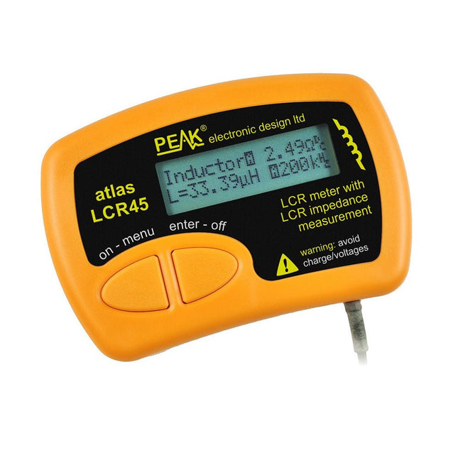
A great handheld LCR analyser that can measure the value of your passive component (inductor, capacitor or resistor) and also measure the detailed impedance in a number of modes. The LCR45 offers enhanced measurement resolution (better than 0.1 uH!) whilst also giving you continuous fluid measurements. Additionally, the test frequencies of DC, 1 kHz, 15 kHz and 200 kHz can be set to automatic or manual modes. Supplied with removable gold plated hook probes, battery and user guide. Compatible with standard 2 mm test connectors. Not designed for in-circuit use.
Automatic or manual component type selection: Inductor, Capacitor or Resistor
Automatic or manual test frequency selection: DC, 1 kHz, 15 kHz and 200 kHz
Inductance from 0.1 uH to 10 H
Capacitance from 0.1 pF to 10,000 uF
Resistance from 0.1 Ohm to 2 MOhm
Inductance measurement also shows DC winding resistance
Display of "Component type and values", "Complex Impedance", "Magnitude/Phase" and "Admittance"
Test frequency displayed for all measurements
Typical accuracy of 1.5% for inductors and capacitors (see spec table for details)
Typical accuracy of 1% for resistors
Test lead complete with gold plated 2 mm plugs and sockets
Supplied with removable gold plated hook probes
Inbegrepen
LCR45
DCA75
Extra GP23 Battery
Extra AAA cell
Dual Carry Case
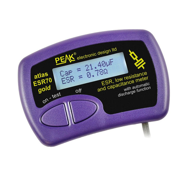
The Peak Atlas ESR70 gold is an enhanced version of the previous Peak Atlas ESR70 Plus. It does everything that the ESR70 Plus did but better.
It now measures capacitance up to 10x faster, and over a wider range, thanks to new test algorithms. The capacitance measurement is also much less influenced by parallel resistances or leakage current thanks to our new Triple-Slope measurement system.
Using the supplied gold plated probes (removable), the Atlas ESR70 gold can measure ESR down to a resolution of 0.01 ohms, up to 40 ohms. It can even measure ESR for capacitors that are in-circuit. Probes are removable, allowing 2 mm compatible probes to be fitted. Audible alerts are produced for various ESR levels allowing you to perform many tests in succession without having to look at the display. The ESR70 automatically takes capacitive reactance into account, so even low value capacitors (down to 0.3 uF) can have the ESR measured accurately.
Kenmerken
Uses a single AAA Alkaline cell (included).
Alphanumeric LCD with backlight.
Automatic analysis-start when you apply the probes.
Automatic capacitor discharge using controlled discharge function.
ESR (and low DC resistance) measurement (even in-circuit).
Capacitive reactance automatically taken into account to ensure accurate ESR.
Capacitance measurement (if testing out-of-circuit).
Audible alerts for various ESR levels.
Extended ESR measurement range up to 40 Ohms.
Optional probe alternatives easily fitted.
New gold Features
Improved LCD with better backlight.
10x faster capacitance measurement for large capacitors.
Enhanced user options system.
New triple-slope measurement system to vastly reduce the influence of parallel resistance and/or leakage current on capacitance measurements.
Much wider capacitance measurement range now 0.3 uF to 90,000 uF (was 1uF to 22,000uF).
Specificaties
Analyzer type
ESR and Capacitance
Component types
Capacitors (>0.3 uF)
ESR range
0.00 Ohms to 40.0 Ohms
ESR resolution
From 0.01 Ohms
In-circuit use
ESR only
Capacitance range
0.3 uF to 90000 uF
Battery type
1.5 V Alkaline AAA Cell (supplied). Life typically 1500 ops
Display type
Alphanumeric LCD (with backlight)
Inbegrepen
Peak Atlas ESR70 gold
Extra-long and extra-flexible test cables (450 mm of Silicone covered cable)
2 mm gold plated plugs and sockets with removeable gold plated crocodile clips
Comprehensive illustrated user guide
AAA Alkaline cell
Downloads
Datasheet (EN)
User Guide (EN)
The LCR45 does everything that the popular LCR40 does, but it has some significant enhancements. The LCR45 features a new high capacity micro and high resolution ADCs.
LCR45 incorporates advanced maths, based on Complex Impedance analysis. This allows for enhanced component value measurement as well as a comprehensive and detailed impedance display.
Kenmerken
Supplied with gold plated removable hook probes.
Fluid measurements with hold function.
Automatic or manual component type.
Automatic or manual test frequency, DC, 1 kHz, 15 kHz or 200 kHz.
Enhanced measurement resolution: 0.2 µH, 0.2 pF and 0.2 Ohms.
Easy menu system for user settings.
Enhanced compensation for component parasitics and losses (such as core losses etc).
Automatic or manual power-off.
Specificaties
Analyser type
LCR and component impedance
Component types
Auto/Manual for L,C & R
Measurement types
Inductance, Capacitance and Resistance
Other measurements
Complex impedance/admittance
More measurements
Magnitude and Phase of impedance
Inductance range
0uH to 2H
Capacitance range
0 pF to 10000 uF
Resistance range
0R to 2MR
Test frequency
Auto and manual: DC, 1 kHz, 15 kHz, 200 kHz
Display type
Alphanumeric LCD (not backlit)
Measurement scheme
Continuous (with optional hold)
Battery
GP23 (12 V/55 mAH type), ~700 ops
Inbegrepen
LCR45 Passive Component Impedance Meter
2 mm plugs and sockets and removeable hook probes
Comprehensive illustrated user guide
2 Batteries, one installed and one spare. GP23 Alkaline battery. (12 V/55 mAH)
Downloads
Datasheet (EN)
User Guide (EN)