Bestsellers
-

Elektor Digital Android, Apps programmeren stap voor stap (E-book)
Steeds vaker komen we op smartphones en tablet-computers het besturingssysteem Android tegen. Het aantal toepassingsprogramma's - de zogenaamde applicaties of kortweg apps - waarmee de apparaten individueel aan de voorkeuren en wensen van de gebruiker kunnen worden aangepast, neemt van dag tot dag toe. En de steeds betere technische uitvoering en uitrusting van de apparaten maken het nu mogelijk toepassingen te 'draaien' waarvoor een paar jaar geleden nog een desktop-PC of speciale hardware vereist was. Inmiddels kan elke smartphone de exacte (geografische) positie bepalen, video's opnemen - en nog veel meer. Maar bij het individualiseren van onze smartphone hoeven we ons niet te beperken tot kant-en-klare applicaties! Het is namelijk helemaal niet zo moeilijk om zelf Android-apparaten te programmeren en eigen apps te schrijven. Dit boek vormt een inleiding tot het programmeren van apps voor Android-apparaten. De werking van het Android-systeem wordt op begrijpelijke manier uitgelegd en we zien stap voor stap hoe applicaties kunnen worden geprogrammeerd. Aan de hand van een groot aantal voorbeelden worden allerlei toepassingsmogelijkheden getoond. Het scala loopt van eenvoudige rekenprogramma's via het uitlezen van sensoren en GPS-data tot het programmeren van applicaties voor internetcommunicatie. Naast het schrijven van applicaties in de programmeertaal Java wordt in dit boek ook besproken hoe apps met behulp van Javascript of PHP-scripts kunnen worden geprogrammeerd.
€ 29,95
Leden: € 26,96
-

Elektor Digital Starten met Internet of Things (E-book)
35 projecten met Raspberry Pi en wireless Arduino Internet of Things (alles aan het internet) is een trend die zich niet meer laat keren. We willen alles in huis met onze mobiel of tablet doen, van Facebook tot TV kijken, van lichten bedienen tot de temperatuur in de gaten houden. In dit boek laten we in 35 leuke en handige projecten zien hoe u op eenvoudige wijze zelf een Internet of Things systeem kunt aanleggen. We gaan in op de hardware (de perfecte combinatie van Raspberry Pi en Arduino) en de software om bediening via internet mogelijk te maken. We maken gebruik van Wi-Fi en radioverbindingen zodat er geen kabels dwars door uw huis hoeven. Wanneer u deze projecten maakt heeft u een compleet Internet of Things systeem waarmee u van alles in uw huis kunt bedienen en bekijken. Bijvoorbeeld of er post in de brievenbus ligt en of de auto in de garage staat. U kunt op vanaf de bank het licht aandoen en het alarm bedienen. Door de heldere uitleg kunt u de projecten eenvoudig aanpassen om bijvoorbeeld uw koffiezetautomaat of tv op afstand aan te zetten. Via de index vindt u gemakkelijk creatieve projecten die als voorbeeld kunnen dienen, zodat u zelfstandig alles met het internet kunt verbinden.
€ 29,95
Leden: € 26,96
-

Elektor Digital PIC Microcontroller Programming (E-book)
in 10 captivating lessons Using the lessons in this book you learn how to program a microcontroller. You’ll be using JAL, a free but extremely powerful programming language for PIC microcontrollers, which enjoys great popularity in the hobby world. Starting out from scratch virtually, you slowly build up the knowledge. No previous knowledge is needed: anyone can get started with this book. Assuming you have absorbed all lessons – meaning you have actually completed all the exercises – you should be confident to write PIC microcontroller programs, as well as read and understand programs written by other people. JAL commands You learn the function of JAL commands such as include, pin, delay, forever loop, while loop, case, exit loop, repeat until, if then, as well as the use of functions, procedures and timer- and port interrupts. JAL programs You make an LED blink, build a time switch, measure a potentiometer’s wiper position, produce sounds, suppress contact bounce, and control the brightness of an LED. And of course you learn to debug, meaning: how to spot and fix errors in your programs. Hardware You learn to recognize various components including the PIC microcontroller, potentiometer and quartz crystal, and how to wire up a PIC microcontroller and effectively link it to your PC. A breadboard is used for the purpose, allowing you to easily modify the component arrangement for further experimenting. The companion software with this book can be downloaded free of charge, including the JAL programming language. In addition, you may order a kit of parts so you don’t have to go shopping for the required components. Especially for a beginner, this is the easiest way to start with this unique pastime. Having finished this book does not mean you are through with your pastime. You can get your hands dirty again, and if desired use other books packed with fun projects using the JAL programming language. More information may be found at the end of the lessons in the chapter "Done! What’s next?""
€ 29,95
Leden: € 26,96
-

Elektor Digital Elektor Novembre/Décembre 2024 (PDF)
Le téléchargement intégral de ce numéro est disponible pour nos membres GOLD et GREEN sur le site Elektor Magazine ! Pas encore membre ? Cliquez ici. Prototypage, production et composants ! carte processeur Audio DSP FXpartie 1 : caractéristiques et conception 50 ans d'Elektor en anglais KiCad 8nouvelles et dernières caractéristiques Elektor @ electronica 2024electronica Fast Forward 2024, des experts sur scène, des forums d'influenceurs, des talk-shows Elektor Lab en direct, et plus encore kit MultiCalculator d'ElektorUn kit de calculatrice basé sur Arduino pour l'électronique systèmes GNSS RTK à faible coûtavec un degré de précision de l'ordre du centimètre routage des Circuits Imprimés et sécuritéConseils pour une conception sure et fiable de vos cartes électroniques testeur d'ampli-oppour les applications audio et autres mise à jour du projet #4 : compteur d'énergie ESP32surveiller l'énergie avec MQTT analyseur de spectre temps-réel à technologie guide d’onde et PC à interfaces multiplesAaronia introduit une nouvelle ligne de produit et présente ses premiers prototypes au salon Electronica de Munich inductances SMTbobines et ferrites – un choix simplifié utilisation d’un blindage EMI pour assurer la conformité à la compatibilité électromagnétique l'outil ultime pour tous les passionnés d’électroniqueDébloquez des possibilités infinies avec Red Pitaya et plus de 1000 Click Boards™ HDI au milieuUn nouveau service PCB-pooling rentable pour des petits BGA défis de l'analyse DFM pour les circuits flexibles et flexibles-rigides outils open-sourcesimulateur d'antennes, gestion des composants, calculatrice, et bien plus Infographie : prototypage et production sur le vifmicrotechnophobie : c’est grave, docteur ? arbre de Noël 3Dcircuit imprimé 3D avec un microcontrôleur 32 bits peu coûteux démarrer en électronique......on continue avec l'ampli-op ! nœud de capteurs autonome (mise à jour du projet #1)Reducing Idle Power Consumption with External RTC and Power Switch 2024 : l'odyssée de l'IAUn regard sur l'avenir afficheurs LED avec le MAX7219Une méthode pratique pour une excellente puce projet 2.0Corrections, mises à jour et courrier des lecteurs gants vibro-tactilesune avancée pour les patients de Parkinson
€ 10,95
-

Elektor Digital Elektor Mars/Avril 2025 (PDF) FR
Le téléchargement intégral de ce numéro est disponible pour nos membres GOLD et GREEN sur le site Elektor Magazine ! Pas encore membre ? Cliquez ici. L'architecture de processeur open-source RISC-V16 cartes et MCU à connaître un lecteur audio avec égaliseur basé sur un FPGAMixage audio numérique avec un Arduino MKR Vidor 4000 tête laser pour l’horloge de sable basé sur Raspberry Pi PicoDessiner avec la lumière participez au concours STM32 Edge AI système de contrôle environnemental multi-capteurs pour les plantesMesure sans fil de l'approvisionnement en eau et de la luminosité porte automatique contrôlée par l'IA et MaixduinoReconnaissance faciale avec une caméra l’électronique embarquée en 2024L’IA va redéfinir l’industrie Calcul en mémoire basé sur la charge chez EnCharge AI des opérations d'IA avec 10 fois moins d'énergie et des coûts divisés par 20 Une carte pour le développement et l’entraînement des modèles ML d’analyse des vibrations Elektor Mini-WheelieKit robot gyropode (robot autostabilisé) MCUViewerMCUViewer outil de débogage open source multiplateforme isolateur USB 2.0Isolation éléctrique pour les périphériques USB anticipation et actionApplication pratique de la maintenance prédictive SPoE – compatibilité électromagnétiquePaire unique avec Power-over-Ethernet à travers les yeux d'EMC rétro-techCréer un monde nouveau avec la télévision couleur surveillance ECGavec des modules Hexabitz et STM32CubeMonitor la bataille pour l’IA en périphérie HaLow atteint une distance Wifi record de 16 km à 900 MHz première puce embarquée CHERI RISC-V et programme d'accès anticipé la détection des incendies de forêt de troisième génération utilise des liaisons satellites sur le vifDélices et supplices du choix démarrer en électronique......Filtrage et contrôle de la tonalité Kit d'horloge quasi-analogiqueNouvelle version d'un classique d'Elektor une approche modulaire de test des capteursCarte de test de capteurs basée sur l'ESP32-S3 2025 : une odyssée de l'IAL'essor des modèles de fondation et leur impact sur l'accessibilité de l'IA Synthétiseur MIDI autonome Raspberry Pi (1)Préparation d'une plateforme pour des expériences d’IA en périphérie projet 2.0Corrections, mises à jour et courrier des lecteurs Le RISC-V AI, un processeur à tout faire : CPU, GPU, DSP, FPGA paroles de PDG : fraîcheur, silence et finesse programmation Dual-Core avec le Raspberry Pi PicoLe monde de la programmation parallèle
€ 10,95
-

Elektor Digital 50 Mini Microcontroller projecten (E-BOOK)
Let op: 2e druk en nieuwe cover! Wie enigszins bekend is met moderne microprocessor systemen als Arduino, kent ongetwijfeld ook de problemen met dit soort kaarten. Ze zijn te duur om voor elk project een aparte kaart aan te schaffen en zijn bovendien nogal fors van formaat. Het aardige van de ATtiny is dat de schijn bedriegt. Het lijkt een klein IC met een beperkt toepassingsgebied, maar het heeft een verbazingwekkend scala aan (speelse) mogelijkheden. Dit boek beschrijft de enorme veelzijdigheid van de ATtiny microcontroller aan de hand van ongeveer vijftig leuke elektronica projecten, speciaal gericht op de beginner. De meeste ontwerpen zijn volledig uitgewerkt, enkele zijn meer als ontwerpidee gepresenteerd. De inhoudsopgave laat zien dat we ons op vele terreinen zullen begeven, van zonnevolger tot helling indicator. Dit boek is beslist geen theorieboek. Het is een boek dat gelezen zal worden met de soldeerbout in de hand. Voor het programmeren van de ATtiny maken we dankbaar gebruik van een Arduino kaart. Als de Arduino ingesteld word als programmer, kunnen we er de meeste Arduino “sketches” mee overzetten naar de ATtiny. We wensen u veel plezier met het nabouwen van de schakelingen.
€ 19,95
Leden: € 17,96
-

Elektor Digital Elektor Summer Circuits 2022 (PDF)
Meer dan 50 schakelingen & projecten US-sirene Twee draai-encoders op één analoge ingang Digitale 220VAC-dimmer met Arduino Stroombron voor LED’s Vier schakelaars detecteren met één pin Kleine aan/uit-schakelaar met accucontrole Desinfectie-dispenser voor zelfbouw Eenvoudig elektronisch orgel Simpele stereoversterker Audiogestuurde schakelaar Gebalanceerd/ongebalanceerd-converter Extern netfilter Knoploze garagedeurbediening DI-box voor smartphone Pret met een looplicht Eenknops-thyristorbesturing Quasi-analoge belichtingstimer voor de donkere kamer Schakelingen bij de Hackster.io-community Analoge zonnebad-timer Weer een eendraads LCD-interface Simpele PWM-generator met AVR ATtiny13 Een tweede leven voor batterijen Aanraakschakelaar voor LED-verlichting Tester voor LED’s en DIP-schakelaars IR-afstandsbedieningstester Tester voor vermogens-halfgeleiders SPI voor WS2812(B)-LED’s Meten van vermogens-zelfinducties Eén stekker voor Raspberry Pi en Audio DAC Doe-het-zelf meetklem voor de LCR-meter Arduino-ampèremeter Tweevinger-orgel Ruisarme ADC-kalibrator DC/DC-boostconverter Twee potmeters op één digitale ingang Akoestische nabijheidssensor Batterijloze radiatorsensor Speurneus voor draadloze camera’s en microfoons Timer voor auto-binnenverlichting Kaarssimulator Digitale keukentimer Milliohm-meter Warmwatervertrager Eenvoudige lader voor twee (of meer) 18650-cellen Mini-frequentiereferentie Zuinige IR-schakelaar Hergebruik de telefoonlader van je auto Microfoon-voorversterker voor Arduino EMI-filters voor zelfbouw Elektronische dobbelsteen zonder MCU Vingercondensator Zelfladende flits-LED Ook in deze editie KiCad 6 – vijf interessante nieuwe functies Retrotronica – de Elektor SC/MP-computer Interview – kunst maken met elektriciteit Mijn eerste print – spring in het diepe... met KiCad Met slimme software de hardware minimaliseren Elektor Infographics – feiten en cijfers Nieuwe componenten van Analog Optimalisering van de signaalintegriteit – Industry 4.0 vereist vlekkeloos werkende interfaces7 Hexadoku – puzzelen voor elektronici
€ 9,95
-

Elektor Digital Elektor AI Guest Edition 2024 (PDF) FR
Le téléchargement intégral de ce numéro est disponible pour nos membres GOLD et GREEN sur le site Elektor Magazine ! Pas encore membre ? Cliquez ici. le système de sécurité IA AlertAlfredBasé sur un Raspberry Pi 5 et le module Hailo 8L l'IA en développement électroniqueune mise à jour après seulement un an intro aux algorithmes de l'IAPrompt: Quels algorithmes implémentent chaque outil d'IA ? ordinateurs monocartes pour les projets d'IAAperçu et contexte des données de capteurs aux modèles d'apprentissage automatiqueDétection de gestes avec Edge Impulse et un accéléromètre créez un neurone d’intégrationet-tir avec fuiteIntelligence artificielle sans logiciel ChatGPT pour la conception électroniqueGPT-4o fait-il mieux ? intégrer l'IA périphérique avec l'ESP32-P4 fonctions vocales sur le Raspberry Pi ZeroWhen Overclocking Gives Freedom of Speech le rôle croissant de l'IA périphériqueUne tendance qui structure l'avenir exploiter la puissance de l'IA en périphérieUn entretien avec François de Rochebouët de STMicroelectronics horloge en VHDL réalisée avec ChatGPT l'impact réel de l'IASayash Kapoor à propos des "faux miracles de l'IA" et plus encore les dernières nouveautés de BeagleBoardBeagleY-AI, BeagleV-Fire, BeagleMod, BeaglePlay et BeagleConnect Freedom détection des moustiques : avec Arduino Nicla Vision et des données open source l'IA d’aujourd'hui et de demain : les idées d'Espressif, d'Arduino et de SparkFun chronologie de l'intelligence artificielle BeagleY-AIThe Latest SBC for AI Applications lumière sur l’IALes perspectives de la communauté Elektor vision artificielle avec OpenMVCréer un détecteur de canettes de soda conversation avec l'esprit numériqueChatGPT vs Gemini "Skilling Me Softley with This Bot?"L'essor de l'IA dans le secteur électronique freiné par une absence de précision sociale ?
€ 10,95
-

Elektor Digital Elektor Mai/Juin 2022 (PDF)
Vos premiers pas avec l'ESP32-C3 et l'IdOBouton Wi-Fi + relais Wi-FiCloud IdO à la sauce ArduinoDétecteur Geiger-Müller à double tube (extension pour Arduino)Capteur très sensible pour très faible rayonnementDétecteur de CO2 : CO2 GuardUne solution « maison » pour surveiller la qualité de l'airKit de mesure de la qualité de l'air pour Raspberry Pi de MonkMakesMesure de température et de CO2eDémarrer en électronique... (13)Entrée en scène de la diodeTrucs et astuces pour tester les composantsSans appareils de test coûteuxRéduction de la consommation d'énergie de votre repousse-taupesGrâce au remplacement du 555 par un ATtiny13Interrupteur crépusculaire DeLuxUne solution pour une commutation de haute précision, commandée par la lumièreLes défis de la commercialisation des solutions IdOProblématiques de sécurité, d'évolutivité et de concurrenceElektor infographieIoT : le nouveau Graal ?« Je préfère quand même être en filaire »Conseils pour développer une interface 1 Gbit/s dans un environnement industrielLa détection d'objets en temps réel pour les microcontrôleurs grâce à Edge Impulse FOMOTubes à ondes progressivesPeculiar Parts, the SeriesNB-IoTNormes, couvertures, conventions et modulesPasserelle intérieure Dragino LPS8Configuration rapide de la passerelle LoRaWANExplorer les microcontrôleurs ATtiny en utilisant le langage C et le langage assembleurExtrait : Ports d'E/S d'ATtinyÉlectronique interactive : projet 2.0Corrections, mises à jour et courriers des lecteursMise à jour de la balise GPS LoRaRecevoir et afficher la localisation à l'aide d'un Raspberry PiSimulation de circuits avec TINA Design Suite & TINACloudExtrait : oscillateurs sinusoïdauxSur le vifFaçon de pincerInfrastructure graphique WinUI pour les applications WindowsApplication de démonstrationCréation d'interfaces graphiques en Python avec guizeroLa pire des interfacesSystèmes solaires autonomesProduction d'électricité indépendante du réseau10 ans avec le même smartphone ?Et si c'était possible !Hexadoku
€ 10,95
-

Elektor Digital Elektor Mars/Avril 2026 (PDF) FR
Le téléchargement intégral de ce numéro est disponible pour nos membres GOLD et GREEN sur le site Elektor Magazine ! Pas encore membre ? Cliquez ici. programmation PIO sur le Raspberry Pi PicoNeuf instructions, de multiples possibilités l'IA en ligne de commandeDéveloppement, compilation et validation de projets embarqués depuis le terminal le Scrutiny DebuggerDéboguer, visualiser et tester du code C/C++ embarqué carte breakout Sigfox (1)Développement d’une BoB radio alimentation à faible bruit (2)Construction, assemblage et mise en œuvre pratique générateur de signaux simple basé sur le RP2040Signaux analogiques et numériques à la découverte du futur de la domotique avec Matter et l’IA EdgeLes dernières versions de Matter et l’essor de l’IA en périphérie de réseau (edge) donnent-ils enfin aux ingénieurs les outils nécessaires pour construire les maisons intelligentes et parfaitement intégrées promises aux utilisateurs ? capteurs de pression différentielleLa maintenance prédictive appliquée aux systèmes CVC la sécurité dès la conceptionPrincipes d’ingénierie pour limiter les défaillances la sécurité des systèmes embarqués n’est plus une option la CRA et la PQC redéfinissent les priorités de la sécurité embarquéePourquoi même les petites entreprises IoT et industrielles doivent prévoir une mise à niveau embedded world 2026Entretien avec Benedikt Weyerer, directeur d’embedded world prise en main du bus I3CUtilisation de matériel de ST et Microchip le projet BLEnkyPrototypage rapide d’applications Bluetooth Low Energy modulation de largeur d’impulsionDu thermostat tout ou rien à un signal analogique continu filtré audiotroniqueDes circuits audio agréables à l’écoute, à réaliser soi-même sur le vifLisez donc le manuel ! carte émetteur-récepteur audio ESP32 (4)Réglage des horloges et une option filaire 2026 : une odyssée de l’IAConséquences du vibe coding charge CC symétriqueCharge CC symétrique, statique ou dynamique comptage de visages avec MaixCAMUne méthode simple pour estimer la taille d’un public
€ 10,95
-

iFixit iFixit Magnetic Project Mat
The 8x10" iFixit Magnetic Project Mat catches and securely holds screws as you pull them out of a device. Now you can stop worrying about keeping track of all the loose screws and focus on your repair. Screws and small parts will remain right where you left them. For laptops with hundreds of screws, use the whole mat as a screw guide and keep careful location notes. Included is a pen — made by Staedtler, producer of top-of-the-line pens and pencils for artists and architects — that was specially designed for the Project Mat. The Lumocolor Correctable pen resists smears and won't wipe away with a casual brush of your hand. When your repair is complete, use the eraser tip or a dry cloth to wipe the ink away clean. Kenmerken Organize all your small parts while you work on a device. The dry-erase surface lets you keep notes and location sketches. Reduces reassembly time by up to 40% while preventing errors.
€ 19,95
-

Elektor Digital Elektor Janvier/Février 2026 (PDF) FR
Le téléchargement intégral de ce numéro est disponible pour nos membres GOLD et GREEN sur le site Elektor Magazine ! Pas encore membre ? Cliquez ici. alimentation de labo à très faible bruit (1)Une source silencieuse pour les circuits sensibles STM32 Edge AI Contest 2025 : les gagnants les batteries aujourd’huiTechnologies et différences entre les batteries au lithium charge électronique réglableCharge CC statique et dynamique convertisseur abaisseur de 48 V à 5 Vune réalisation pratique nœud de capteurs autonome v2.0Partie 2 : validation matérielle et optimisations énergétiques varistancesDrôles de composants, la série compteur graphique de fréquence du réseauSurveillance de la qualité du réseau démarrer en électronique…Touche à sa fin ferrites CMS à charge de courant de crêteplus résistantes aux pics de courant Elektor Live! Expert Day 2025 la récupération d’énergie propulse l’IoT et l’IIoT vers une nouvelle èreLa récupération d’énergie affranchit l’IoT de la dépendance au réseau Fnirsi DPS-150Alimentation portable compacte et convertisseur source d’alimentation USB-C réglableTransformez votre chargeur USB-C en alimentation réglable chargeur simple et testeur de capacitéAvec deux modules économiques « prêts à l’emploi » détecteur de couleurs intelligent avec synthèse vocale et lecture audio basées sur l’IA PbMonitor v2.0Présentation du système de surveillance de batteries mis à jour un ventilateur pour la mini-plaque de refusionDes modifications astucieuses pour des résultats optimisés sur le vifL’excès d’indulgence projet 2.0Corrections, mises à jour et courriel des lecteurs 2026 : une odyssée de l’IAQuand les modèles commencent à orienter le matériel picoampèremètre de précision (2)Assemblage, étalonnage et test alimentation sans fil des appareilsavec technologie inductive conduite autonome basée sur l’IALe Self Driving Challenge 2024 du RDW carte son comme générateur de signauxUn PC utilisé comme émetteur de test DCF77
€ 10,95
-
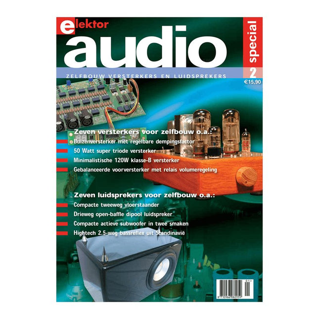
Elektor Digital Elektor Special: Audio 2 (PDF)
Zelfbouw versterkers en luidsprekers Deze speciale uitgave staat vol met interessante bouwbeschrijvingen en achtergrondartikelen van internationaal gerenommeerde ontwerpers. Het gaat in alle gevallen om nieuwe, nog niet eerder gepubliceerde artikelen. Inhoudsopgave Buizenversterkers 30 Watt buizenversterker met variabele dempingsfactor 50 Watt super triode versterker 300 Watt buizen eindversterker Digibias: digitaal de ruststroom instellen en bewaken Luidsprekers Paper Hatt - klein maar fijn Origami M en C – compacte actieve subwoofer in twee smaken Meerweg open baffle systemen – basistheorie, ontwerp en meetmethode Moai – hightech uit Scandinavië OB3W – drieweg open-baffle dipool van formaat 1685a – compacte tweeweg vloerstaander ScanSpeak Vertigo – duizelingwekkend mooi driewegsysteem Halfgeleiderversterkers MinimA – minimalistische 120W klasse-B versterker Gebalanceerde voorversterker met actief wisselfilter RelaiXed – gebalanceerde voorversterker met relais
€ 15,90
Leden: € 14,31
-
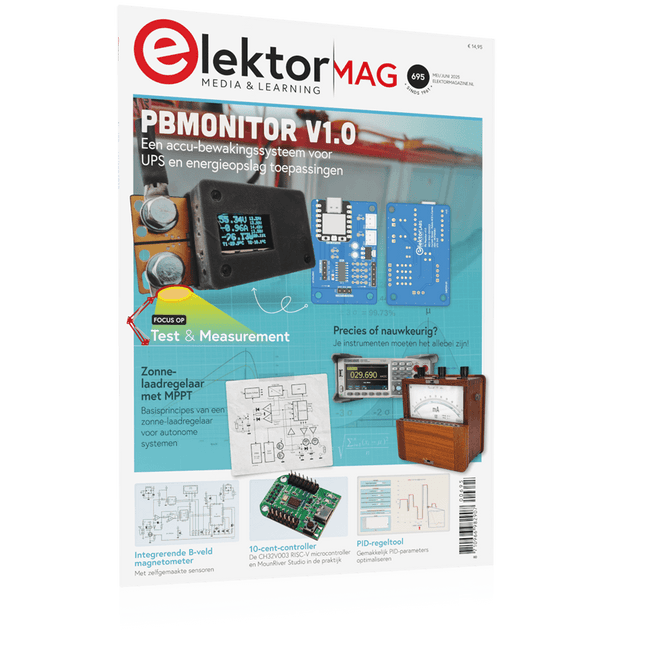
Elektor Mei/Juni 2025 (NL)
Elektor GREEN en GOLD leden kunnen deze uitgave hier downloaden. Nog geen lid? Klik hier om een lidmaatschap af te sluiten. PbMonitor v1.0Een accu-bewakingssysteem voor UPS en energieopslag toepassingen Zonne-laadregelaar met MPPT (1)basisprincipes van een zonne-laadregelaar voor autonome systemen Integrerende B-veld magnetometermet zelfgemaakte sensoren Precies of nauwkeurig?Je instrumenten moeten het allebei zijn! AD7124 Een precisie-ADC in de praktijkEssentieel voor Sensorsignaalconditionering PID-regeltoolGemakkelijk PID-parameters optimaliseren embedded world 2025 Alle begin......gaat verder met de toonregeling Academy Pro BoxBoek + onlinecursus + hardware Milliohmmeter adapterGebruik de nauwkeurigheid van uw multimeter De volgende sprong in halfgeleidersVoorwaarts naar 1,4nm Through-hole connectorenHet beste van twee werelden: THR FrequentietellerDraagbaar en Automatische Kalibratie met GPS Analoge metersVreemde onderdelen, de serie Stand-alone kristaltesterhoe nauwkeurig is uw kloksignaal? Goedkope I²C-testersluit I²C-apparaten rechtstreeks op uw PC aan Uit het leven gegrepenwie het kleine niet eert... 2025: een AI-odysseede transformerende invloed op softwareontwikkeling Err-lectronicsCorrecties, updates en ingezonden brieven Raspberry Pi standalone MIDI-synthesizer (2)We verbeteren onze setup met intelligentie Norton-getransformeerde wienbrug-oscillatorkleine verandering, grote verbetering Test van een 10-cent-controllerde CH32V003 RISC-V microcontroller en MounRiver Studio in de praktijk Een FPGA-gebaseerde audiospeler met equalizer (2)volumeregeling, geavanceerd mixen en een webinterface
€ 14,95
-

Elektor Maart/April 2025 (NL)
Elektor GREEN en GOLD leden kunnen deze uitgave hier downloaden. Nog geen lid? Klik hier om een lidmaatschap af te sluiten. De open-source processorarchitectuur RISC-V16 boards en MCU's die je moet kennen Een FPGA-gebaseerde audiospeler met equalizer (1)Digitaal audio mixen met een Arduino MKR Vidor 4000 Laserkop voor pico-gebaseerde zandklokTekenen met licht Doe mee aan de STM32 Edge AI Contest Een multi-sensor plantenmonitor-systeemdraadloze meting van watertoevoer en lichtomstandigheden Maixduino AI-gestuurde automatische portiergezichtsdetectie met een camera Embedded Electronics 2024AI gaat de industrie opnieuw vormgeven Lading-gebaseerde in-Memory computing bij EnCharge AI AI-Inferentie met 10 Keer Lager Energieverbruik en 20 Keer Lagere Kosten Click board ondersteunt het ontwikkelen en trainen van ML-modellen voor trillingsanalyse De Elektor Mini-WheelieEen kit voor een zelfbalancerende robot MCU, ik zie jeMCUViewer: open-source multiplatform debugging-tool USB 2.0-isolatorelektrisch geïsoleerde USB-aansluiting Voorkomen is betervoorspellend onderhoud in de praktijk SPoE – Elektromagnetische compatibiliteitSingle pair met Power-over-Ethernet door de ogen van EMC Retro techEen nieuwe wereld met kleurentelevisie ECG-monitorimplementatie met Hexabitz-modules en een STM32CubeMonitor De strijd om AI aan de edge Met HaLow Wi-Fi is een record afstand bereikt van 16 km op 900 MHz Eerste CHERI RISC-V Embedded Chip en Early Access programma Derde generatie bosbranddetectie maakt gebruik van satellietverbindingen Uit het leven gegrepenkeuzestress Alle begin......filtert verder en regelt tonen Quasi-analoog uurwerkwedergeboorte van een Elektor-klassieker Een modulaire sensortesterSensor-evaluatieboard met ESP32-S3 2025: Een AI-OdysseeDe opkomst van foundation modellen en hun rol in het democratiseren van AI Raspberry Pi standalone MIDI-synthesizer (1)voorbereiding van een platform voor enkele edge-AI-experimenten Err-lectronicsCorrecties, updates en brieven van lezers Universele AI RISC-V processor doet ze allemaal - CPU, GPU, DSP, FPGA Interview met de CEO: Ventiva's dunne en coole technologie Dual-core programmeren met een Raspberry Pi Picoduik in de wereld van parallel programmeren
€ 14,95
-

Elektor Digital Elektor Januari/Februari 2023 (PDF)
Elektor GREEN en GOLD leden kunnen deze uitgave hier downloaden.Nog geen lid? Klik hier om een lidmaatschap af te sluiten. Voor ogen en oren Video-output met microcontrollers (1)Composiet Video electronica 2022nieuws van 's werelds grootste elektronicabeurs ESP32-camerazo simpel – heeft niet eens WiFi ATX-voeding voor Raspberry Pi 32 ? KoptelefoonversterkerEenvoudige maar hoogwaardige 3-chip oplossing SDR-radioklokkenvijf tijdsignalen, zes displays Alle begin......zet een streep onder de diode Uit het leven gegrepenover de kwaliteit der dingen Reverse-engineering van een Bluetooth Low Energy LED-badgeeen BLE-apparaat besturen met een Python-script MakePython ESP32 Development KitAlles in een doosje THD-meting met een oscilloscoop en FFTgemakkelijke berekening van de vervormingsfactor Allesziende machinesde technologie achter moderne industrële visionsystemen Infographics De evolutie van spraak- en audiogestuurde elektronische apparaten WEEF 2022 terugblik FFWD elektronica 2022 terugblikde vernieuwers hebben niet nagelaten indruk te maken The Tubeeen ongebruikelijke buizenversterker Biomateriaal in elektronica: klaar of niet De Opera Cake antenne switch voor HackRF OneSluit tot acht antennes aan op uw SDR Engineering met de Arduino, en meerEen interview met auteur Ashwin Pajankar LiDAR-precisiemetermeet tot 12 meter Audiosignalen en de ESP32De ESP-ADF-omgeving in de praktijk Elektor Fortissimo-100 einversterker-kit Lichtgestuurde geluidseffectenSpanningsgestuurd 24 dB/oct synthesizerfilter (VCF) met LDR's De kilo-watter van Elektuurmeer volume gaat niet! Oost West Lab Besteen volumetrisch display in Canada Project 2.0Correcties, Updates en Brieven van lezers Hexadoku
€ 9,95
-

Elektor Digital Elektor Juli/Augustus 2021 (PDF)
LORA MET DE RASPBERRY PI PICOpret met MicroPython WAT IS RISC-V?en waarom de industrie zo enthousiast is over een nieuwe processorkern! ELEKTOR @ 60de Halfgeleidergidsen VEELZIJDIGE VOEDING VOOR BREADBOARDSplus en min uit 5 V van USB RASPBERRY PI PICO ESSENTIALSvoorbeeldhoofdstuk: WiFi met de Raspberry Pi Pico MAGNETISCHE LEVITATIE “THE EASY WAY” KENNISMAKING MET DE PARALLAX PROPELLER 2 (DEEL 3)smart pins en seriële data (UART) NUCLEO-BOARDS PROGRAMMEREN MET DE STM32CUBEIDEvoorbeeldhoofdstuk: FreeRTOS voor de STM32-MCU UITBREIDING VAN DE MT3608 DC-DC STEP-UP CONVERTERMODULE MINIWARE DT71 DIGITAL TWEEZERS WEARABLE WIFI-GADGETESPHome, uw steun en toeverlaat ALLE BEGIN......sluit het onderwerp “condensatoren” hiermee af EENVOUDIGE SKETCHES MET BEHULP VAN HET QWIIC-ECOSYSTEEM JAVA OP DE RASPBERRY PIdeel 2: GPIO’s besturen met een REST-service van Spring RASPBERRY PI COMPUTE MODULE 4een Raspberry Pi voor de industrie DRAAGBAAR STAND-ALONE LUCHTKWALITEIT-DISPLAY VOOR 2,5MM-DEELTJEShoud(t) een oog op uw gezondheid UIT HET LEVEN GEGREPENvroeger was de toekomst beter MICROPYTHON VOOR DE ESP32 EN CONSORTENdeel 1: installatie en onze eerste programma’s CHARGE COUPLED DEVICES IN OSCILLOSCOPENvreemde onderdelen ESD – DE ONZICHTBARE VIJANDbliksem bij heldere hemel vernielt componenten ZONNE-ENERGIE VOOR MAAIROBOTSecologisch, goedkoop, eenvoudig! EUROPA’S INSPANNINGEN OM BIG TECH TE TEMMEN HEXADOKUThe Original Elektorized Sudoku
€ 9,95
-

Elektor Publishing SDR with HackRF One & HackRF Pro
Programming with GNU Radio HackRF is an open-source hardware platform developed by Great Scott Gadgets and serves as a versatile front end for software-defined radio (SDR). With HackRF One and its successor, HackRF Pro, users can develop their own SDR applications, build powerful receivers and transmitters, and tackle demanding RF measurement tasks. This book provides a practical introduction to the world of SDR. Step by step, the author shows how powerful SDR projects can be implemented with HackRF – from the fundamentals of RF technology to advanced applications using GNU Radio. In addition to working with SDR Sharp (SDR#), RadioConda, and GNU Radio, the book also covers the fundamentals of modern digital signal processing. Numerous experiments and easy-to-follow practical examples guide readers through topics such as AM, FM, and SSB reception, digital filters, shortwave radio, amateur radio, signal generators, and custom RF projects up to 6 GHz. Whether you are a maker, radio amateur, electronics enthusiast, or SDR beginner, this book provides solid knowledge, practical applications, and the motivation to creatively explore the possibilities of modern SDR technology.
€ 24,95
Leden: € 22,46
-

Elektor Digital ESP32 programmeren voor beginners (E-book)
In ESP32 programmeren voor beginners bekijken we de ESP32 en zijn voorganger, de ESP8266. Deze kleine, maar zeer krachtige Chinese chips bestaan uit een processor, geheugen, input- en outputaansluitingen en hebben draadloze netwerktoegang via WiFi. Met dit boek tonen we hoe de programmeeromgeving Arduino werkt en hoe die kan gebruikt worden met ESP-hardware. Aan de hand van voorbeelden en projecten verduidelijken we hoe de ESP-hardware kan worden toegepast. In vogelvlucht: We beschrijven de opbouw van ESP-experimenten. We tonen hoe displays worden aangesloten. Eeprom_24c16 demonstreert hoe een externe geheugenchip wordt gebruikt om getallen en tekst op te slaan en weer uit te lezen. Project Klok is de eenvoudige implementatie van een digitale klok. We geven een handleiding voor het gebruik van temperatuur- en luchtvochtigheidsensoren. Webclient laat zien hoe de ESP32 gegevens van het internet kan halen. Met Webserver kunnen we op afstand met een pc of smartphone gegevens halen uit een ESP32, sensoren uitlezen en toestellen aan- en uitschakelen. Een NTP-klok haalt tijdinformatie van Tijdserver. Die geeft zowel de tijd als het aantal seconden sinds 1 januari 1900. Het boek beschrijft hoe hieruit de tijd kan worden berekend. In het laatste hoofdstuk gebruiken we het internet om nauwkeurige weerinformatie en voorspellingen op te vragen.
€ 24,95
Leden: € 22,46
-

Elektor Digital Elektor Januari/Februari 2022 (PDF)
MOTOREN AANSTUREN MET H-BRUGGENeen inleiding tot gelijkstroom-, stappen- en borstelloze motoren HET ELEKTOR LAB-TEAMonze aanpak, onze tools – en meer... RASPBERRY PI ALS KVM-AFSTANDSBEDIENINGsoftwaretest Pi-KVM IQAUDIO CODEC ZEROgeluidskaart voor de Raspberry Pi-familie WAT WE KUNNEN LEREN VAN HET PIKVM-PROJECTeen vraaggesprek met Maxim Devaev AUTONOOM RIJDEN MET 2D-LIDARESP32 Pico interpreteert gegevens van de lidar-module DE RASPBERRY PI ZERO 2 W GAAT QUAD-CORE NOTITIES BIJ VAN HET WORLD ETHICAL ELECTRONICS FORUM 2021 MOTORBESTURINGhoe de complexiteit van motorbesturing wordt gereduceerd GROTE ELEKTROMOTORENbasisprincipes en nuttige informatie AAN DE SLAG MET DE ESP32-C3 RISC-V MCU BESCHERM UZELF EN ANDEREN!DHZ-hoofdschakelaar voor uw werkbank GUI'S MAKEN MET PYTHON (DEEL 2)Spionnennaamkiezer PRODUCTRONICA FAST FORWARD 2021: DE WINNAARSspannende technologieën en creatieve engineeringoplossingen VEELZIJDIGE SERVOTESTERcontroleer het gedrag, ook zonder datasheet MODBUS VIA WLANdeel 2: software voor de Modbus TCP WLAN-module KENNISMAKING MET NEURONEN IN NEURALE NETWERKENdeel 3: neuronen in de praktijk IN EEN OPEN SOURCE-PROCESSORvoorbeeldhoofdstuk: vergelijking van Lattice- en Xilinx-FPGA’s ALLE BEGIN......is nog niet klaar met de spoel PROJECT 2.0correcties, updates en brieven van lezers KLEUR NAAR GELUIDeen kleursensor via I2C uitlezen BATTLAB-ONEmeet en optimaliseer de gebruiksduur van IoT-accu’s EENVOUDIGE AARDLEKTESTERisolatietest voor lichtnetinstallaties ARMOEDE EN ELEKTRONICAhet streven naar duurzame ontwikkeling HEXADOKUpuzzelen voor elektronici
€ 9,95
-

Elektor Digital Elektor November/December 2021 (PDF)
BEELDVERWERKING MET DE NVIDIA JETSON NANO (DEEL 2)Beeldherkenning met Edge Impulse NIEUWS VAN ELEKTOR JUMPSTARTERNieuwe campagnes EEN OPEN SOURCE-PLATFORM VOOR GPS-TRACKINGMet Traccar voertuigen volgen zonder gebruik te maken van een cloudserver JOY-IT LCR-T7 MULTIFUNCTIONELE TESTERVoor passieve componenten, discrete halfgeleiders en IR RUISSYNTHESIZERVan ruis naar muziek met de PRBSynth1 ALLE BEGIN......speelt verder met de spoel KENNISMAKING MET NEURONEN IN NEURALE NETWERKEN (DEEL 2)Logische Neuronen BEVEILIGINGSPROBLEMEN? BESTRIJD VUUR MET VUUR!Met flitslampje beveiligde analoge geheugenuitbreiding voor de verzendbox met manipulatie-indicatie LCR METER POSTER BLUETOOTH-BAKENS IN DE PRAKTIJKindoor-plaatsbepaling PROGRAMMEREN IN C OP DE RASPBERRY PICommunicatie via WiFi (een hoofdstuk als voorbeeld) EMC PRE-COMPLIANCE TEST VOOR UW DC-GEVOED PROJECT (DEEL 2)De hardware en het gebruik ervan KENNISMAKING MET DE PARALLAX PROPELLER 2 (DEEL 5)Smart Pin-Functie MODBUS VIA WLAN (DEEL 1)Hardware en programmering OOST WEST LAB BEST... waar de Junior Computer weer tot leven is gewekt BOUW ZELF EEN NAUWKEURIGE KALIBRATOR-10 V tot +10 V, 0 tot 40 mA, 0,001% REVIEW: ARDUINO NANO RP2040 CONNECTRaspberry Pi RP2040 + WiFi + Bluetooth DE FYSIEKE KANT VAN KUNSTMATIGE INTELLIGENTIE PROJECT 2.0Correcties, Updates en Brieven van lezers MAAK GUI'S MET PYTHONIntroductie in guizero CO2-METER-BOUWKIT VOOR IN DE KLASEen ESP8266-project van de University of Applied Sciences Aachen NOSTALGISCHE MK484 MW/LW-RADIO...Altijd leuk om te bouwen! ELEKTOR @ 60Laat er licht zijn! HEXADOKUThe Original Elektorized Sudoku
€ 9,95
-

Elektor Edge Impulse Guest Edition 2025 (NL)
Elektor GREEN en GOLD leden kunnen deze uitgave hier downloaden. Nog geen lid? Klik hier om een lidmaatschap af te sluiten. Wat is Edge-AI nu eigenlijk?Intelligentie naar het apparaat brengen Maak kennis met Edge Impulse StudioEenvoudig Edge-AI modellen bouwen en implementeren Keyword spotting met Edge ImpulseVerzamelen, trainen en implementeren Slimme apparaten bedienen via spraakbesturing met de Nordic Thingy:53 Sleutelbegrippen voor het begrijpen van Edge AI en Machine Learning Snelcursus: Aan de slag met Edge ImpulseLeer een ML-model te verzamelen, trainen en implementeren met de Arduino Nano 33 BLE Sense Een nieuw hoofdstuk voor ArduinoVan hobbyboard tot Edge computing-krachtpatser Aan de slag met objectdetectie op edge-apparaten Detectie van defecten op printplatenComputer Vision met de Raspberry Pi AI op maat maken voor de kleinste apparaten Optimalisatie van het energieverbruik in batterijgevoede Edge-AI apparaten AI ToasterWanneer Edge-AI en ontbijt samenkomen Thundercomm Rubik Pi 3Raspberry Pi ervaring in combinatie met Edge AI Leiderschap, Embedded ML en de Edge-revolutie Vision language models voor EdgeModel-cascadering voor betere betrouwbaarheid Maak kennis met Edge ImpulseVragen van de Elektor-community Projectupdate #5: Energiemeter op basis van ESP32Edge-AI gebruiken voor herkenning van huishoudelijke verbruikers Bewegingsherkenning met anomalie-detectieEen uitgebreide training Slim ventilatiesysteem: integratie van geluids- en omgevingsgegevensEen machine learning toepassing met dubbele MCU voor geautomatiseerde bediening van ramen en lamellen Spraakbesturing voor oordopjes en headsets Edge-AI: de volgende generatie apparaten mogelijk maken
€ 15,95
-

Siglent Siglent SDG2042X Arbitrary Waveform Generator (40 MHz)
Siglent's SDG2000X is a series of dual-channel function/arbitrary waveform generators with specifications of up to 120 MHz maximum bandwidth, 1.2 GSa/s sampling rate and 16-bit vertical resolution. The proprietary TrueArb & EasyPulse techniques help to solve the weaknesses inherent in traditional DDS generators when generating arbitrary, square and pulse waveforms. With advantages above, SDG2000X can provide users with a variety of high fidelity and low jitter signals, which can meet the growing requirements of complex and extensive applications. Kenmerken Dual-channel, 40 MHz bandwidth, 20Vpp maximum output amplitude, high fidelity output with 80dB dynamic range. High-performance sampling system with 1.2GSa/s sampling rate and 16-bit vertical resolution. No detail in your waveforms will be lost. Innovative TrueArb technology, based on a point-by-point architecture, supports any 8pts~8Mpts Arb waveform with a sampling rate in range of 1?Sa/s~75MSa/s. Innovative EasyPulse technology, capable of generating lower jitter Square or Pulse waveforms, brings a wide range and extremely high precision in pulse width and rise/fall times adjustment. Plenty of analog and digital modulation types: AM, DSB-AM, FM, PM, FSK, ASK and PWM. Sweep and Burst functions. High precision Frequency Counter. Standard interfaces: USB Host, USB DeviceUSBTMC, LAN (VXI-11) Optional interface: GPIB. 4.3” touch screen display for easier operation. Specificaties Maximum output frequency 40 MHz Output channels 2 Sampling rate 1.2 GSa/s (4X Interpolation) Wave length CH1: 16Kpts, CH2: 512Kpts Frequency resolution 1 μHz Vertical resolution 16 bit Standard interfaces Standard interfaces: USB Host, USB Device (USBTMC), LAN (VXI-11) High-performance Sampling System Benefiting from a 1.2GSa/s and 16-bit sampling system, SDG2000X achieves extremely high accuracy performance in both time domain and amplitude, which results in more accurately reconstructed waveforms and lower distortion. Innovative EasyPulse Technology When a Square/Pulse waveform is generated by DDS, there will be a one-clock-jitter if the sampling rate is not an integer-related multiple of the output frequency. SDG2000X EasyPulse technology successfully overcomes this weakness in DDS designs and helps to produce low jitter Square/Pulse waveforms. Innovative TrueArb Technology For arbitrary waveforms, TrueArb not only has all the advantages of traditional DDS, but also eliminates the probability that DDS may cause serious jitter and distortion. Easy controll with 4.3” Touch Screen Display and Arbitrary Waveform Software EasyWave The 4.3” touch screen display, makes operation much more convenient. And EasyWave is a powerful arbitrary waveform editing software that supports several ways to generate arbitrary waveform such as manual drawing, line-drawing, equation-drawing, coordinate-drawing, etc. It is quite convenient for users to edit their own arbitrary waveforms through EasyWave. Inbegrepen Siglent SDG2042X Arbitrary Function Generator User Manual Guarantee Card CD (including EasyWave 1.0 computer software system) Power Cord USB Cable Quick Start Guide
€ 560,39
-

Siglent Siglent SPD3303X 3-kanaals DC-voeding (220 W)
Deze SPD3000X Series Linear Programmable DC Power Supply heeft een 4,3-inch TFT LCD-scherm, is te programmeren en heeft Real Time Wave Display, wat gebruikers een geheel nieuwe ervaring geeft. Hij heeft drie aparte uitgangen: twee regelbare uitgangen, en een instelbare uitgang van 2,5V, 3,3V en 5V. Hij heeft ook beveiligingsfuncties tegen kortsluiting en overbelasting, en kan goed worden ingezet bij productie en ontwikkeling. Kenmerken 3 onafhankelijk instelbare en apart uitgevoerde uitgangen: 32V/3,2A×2, 2,5V/3,3V/5V/3,2A×1, totaal 220W. 5 digit spannings- en 4 digit stroomweergave, minimale resolutie: 1mV/1mA. Ondersteunt panel timing uitgangsfuncties. 4,3-inch true color TFT LCD-scherm, 480 x 272 pixels. 3 soorten uitgangsmodi: onafhankelijk, serie, parallel. 100V/120V/220V/230V compatibel ontwerp, om te kunnen worden aangesloten op verschillende elektriciteitsnetten. Intelligente temperatuur-gestuurde ventilator, waardoor het geluid effectief verminderd wordt. Duidelijke grafische interface, met golfvorm weergave functie. Intern 5 groepen van systeemparameters op te slaan / op te vragen, ondersteuning voor uitbreiding van de data opslagruimte. Met PC-software: Easypower, ondersteunt SCPI, LabVIEW driver. Uitgangen met hoge resolutie en hoge precisie De hoge resolutie van 1mV/1mA zorgt voor een uitstekende instel- en afleesnauwkeurigheid. Dit zorgt voor een zeer precieze uitvoer, zelfs bij zeer kleine veranderingen in spanning of stroom. Dit zou onmogelijk zijn bij een voeding met een lage resolutie. Serie/parallel/onafhankelijke uitgang De serie- en parallelfunctie maakt het mogelijk om twee kanalen te combineren in één uitgang met meer uitgangsvermogen, waardoor het aantal toepassingen kan worden uitgebreid. Elk van de 3 kanalen kan onafhankelijk worden in- of uitgeschakeld, of ze kunnen allemaal tegelijk worden in- of uitgeschakeld. Paneel geeft de output timing weer Via het bedieningspaneel kunnen 5 groepen timing-instellingen en de output controle worden weergegeven, wat gebruikers een eenvoudige power-programmeer functie geeft. Er kan ook een verbinding worden gemaakt met Siglent's EasyPower PC-software, die een volledig scala aan communicatie- en besturingsopties biedt. Instelparameters opslaan/opvragen De programmeerbare voeding van de SPD3000X-serie kan 5 groepen instellingsparameters in de interne opslag opslaan of hieruit opvragen, en ondersteunt tevens uitbreiding van externe opslag. U kunt daarmee eenvoudig de benodigde instellingen opvragen.
€ 600,50


