The Piccolino rapid development board can be used to design microcontroller circuits quickly. The Piccolino has a fast 16f887 PIC microcontroller, voltage regulator, and communications module, and can be easily extended using its four headers.
This e-book contains 30 projects based on the Piccolino. We'll use its unique communications facilities and get the Piccolino to communicate with programs on a PC. On the PC, we use the free programming language Small Basic. You can use this to create Windows programs with buttons and graphs quickly. You will learn how to analyze components such as inductors, capacitors, and OPAMPs, and how to display the measurement results in a graphical format. This will help you to design your circuits easily.
We will then start to adapt to the Piccolino. We'll add components to it to make it more powerful, with extra features such as flow control and digital to analog conversion. The clear instructions will enable you to design and build your adaptations. This way you can make your custom designed Piccolino.
We'll end up making an extension: a PCB that that can be mounted on the Piccolino headers. As an example, we'll design and build an extension for an LCD. You can use the included board layout to make your PCB or have it made for you. At the same time, you will learn how to make your extensions. The only limitation is your imagination!
The clear descriptions along with circuit diagrams and photos, will make the building of these projects an enjoyable experience. Each project has a clear explanation of the reasons why it was designed in a particular way. This helps you learn a lot about the Piccolino, as well as Small Basic, and the components that are used in this e-book. You can adapt the projects to suit your requirements or combine several projects.
The Arduino Uno is an open-source microcontroller development system encompassing hardware, an Integrated Development Environment (IDE), and a vast number of libraries. It is supported by an enormous community of programmers, electronic engineers, enthusiasts, and academics. The libraries in particular really smooth Arduino programming and reduce programming time. What’s more, the libraries greatly facilitate testing your programs since most come fully tested and working.
The Raspberry Pi 4 can be used in many applications such as audio and video media devices. It also works in industrial controllers, robotics, games, and in many domestic and commercial applications. The Raspberry Pi 4 also offers Wi-Fi and Bluetooth capability which makes it great for remote and Internet-based control and monitoring applications.
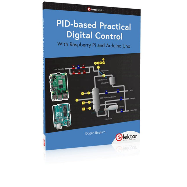
This book is about using both the Raspberry Pi 4 and the Arduino Uno in PID-based automatic control applications. The book starts with basic theory of the control systems and feedback control. Working and tested projects are given for controlling real-life systems using PID controllers. The open-loop step time response, tuning the PID parameters, and the closed-loop time response of the developed systems are discussed together with the block diagrams, circuit diagrams, PID controller algorithms, and the full program listings for both the Raspberry Pi and the Arduino Uno.
The projects given in the book aim to teach the theory and applications of PID controllers and can be modified easily as desired for other applications. The projects given for the Raspberry Pi 4 should work with all other models of Raspberry Pi family.
The book covers the following topics:
Open-loop and closed-loop control systems
Analog and digital sensors
Transfer functions and continuous-time systems
First-order and second-order system time responses
Discrete-time digital systems
Continuous-time PID controllers
Discrete-time PID controllers
ON-OFF temperature control with Raspberry Pi and Arduino Uno
PID-based temperature control with Raspberry Pi and Arduino Uno
PID-based DC motor control with Raspberry Pi and Arduino Uno
PID-based water level control with Raspberry Pi and Arduino Uno
PID-based LED-LDR brightness control with Raspberry Pi and Arduino Uno
The Arduino Uno is an open-source microcontroller development system encompassing hardware, an Integrated Development Environment (IDE), and a vast number of libraries. It is supported by an enormous community of programmers, electronic engineers, enthusiasts, and academics. The libraries in particular really smooth Arduino programming and reduce programming time. What’s more, the libraries greatly facilitate testing your programs since most come fully tested and working.
The Raspberry Pi 4 can be used in many applications such as audio and video media devices. It also works in industrial controllers, robotics, games, and in many domestic and commercial applications. The Raspberry Pi 4 also offers Wi-Fi and Bluetooth capability which makes it great for remote and Internet-based control and monitoring applications.
This book is about using both the Raspberry Pi 4 and the Arduino Uno in PID-based automatic control applications. The book starts with basic theory of the control systems and feedback control. Working and tested projects are given for controlling real-life systems using PID controllers. The open-loop step time response, tuning the PID parameters, and the closed-loop time response of the developed systems are discussed together with the block diagrams, circuit diagrams, PID controller algorithms, and the full program listings for both the Raspberry Pi and the Arduino Uno.
The projects given in the book aim to teach the theory and applications of PID controllers and can be modified easily as desired for other applications. The projects given for the Raspberry Pi 4 should work with all other models of Raspberry Pi family.
The book covers the following topics:
Open-loop and closed-loop control systems
Analog and digital sensors
Transfer functions and continuous-time systems
First-order and second-order system time responses
Discrete-time digital systems
Continuous-time PID controllers
Discrete-time PID controllers
ON-OFF temperature control with Raspberry Pi and Arduino Uno
PID-based temperature control with Raspberry Pi and Arduino Uno
PID-based DC motor control with Raspberry Pi and Arduino Uno
PID-based water level control with Raspberry Pi and Arduino Uno
PID-based LED-LDR brightness control with Raspberry Pi and Arduino Uno
Features Build in USB to Serial interface Build-in PCB antenna Powered by Pineseed BL602 SoC using Pinenut model: 12S stamp 2 MB Flash USB-C connection Suitable to breadboard BIY project On board three color LEDs output Dimensions: 25.4 x 44.0 mm Note: USB cable is not included.
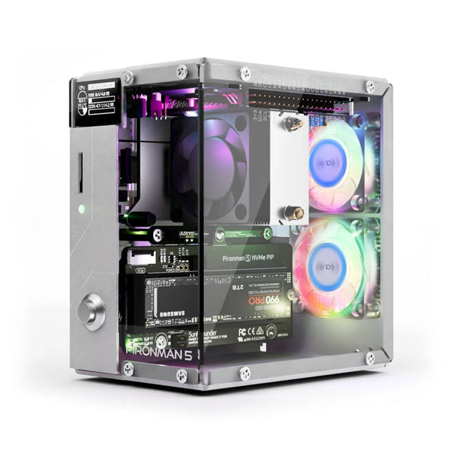
Verbeter je Raspberry Pi 5 met de Pironman 5, gebouwd met stevig aluminium, superieure koeling, NVMe M.2 SSD-ondersteuning, OLED-display, RGB-verlichting, standaard HDMI-poorten x2 en een veilige aan/uit-schakelaar. Het is perfect voor NAS, Home Assistant, Media en Game Centers. De Pironman 5 is niet zomaar een behuizing; het is een upgrade die uw Raspberry Pi 5 verandert in een krachtig, efficiënt en stijlvol apparaat.
De Pironman 5 bevat de Pi 5 NVMe PIP (PCIe Peripheral Board), een PCIe-adapterkaart die speciaal is ontworpen voor NVMe solid-state drives. Dit bord ondersteunt NVMe SSD's in vier formaten: 2230, 2242, 2260 en 2280, die allemaal in een M.2 M key-slot kunnen worden geïnstalleerd. De verbinding is gecertificeerd voor Gen2.0-snelheden (5 GT/sec), maar kan worden geforceerd naar Gen 3.0 (10 GT/sec) voor snellere prestaties.
Uitbreidbaar NVMe M.2 SSD-slot
Verbeter de prestaties van uw Raspberry Pi 5 met de NVMe M.2 SSD-sleuf van de Pironman 5, die meerdere formaten ondersteunt (2230, 2242, 2260, 2280) voor meer opslag en snellere systeemreactie.
Geavanceerd koelsysteem
Houd je Raspberry Pi 5 koel en stijlvol met de torenkoeler en dubbele RGB-ventilatoren van de Pironman 5, voorzien van stoffilters voor een duurzame en onderhoudsarme werking.
OLED-display voor direct inzicht
De Pironman 5 heeft een OLED-scherm van 0,96 inch, dat onmiddellijke updates biedt over CPU- en RAM-gebruik, temperatuur, IP-adres en meer.
Verbeterde functionaliteit en veiligheid
De Pironman 5 beveiligt je Raspberry Pi 5 met functies zoals veilig uitschakelen, aanpasbare RGB-LED's, HDMI-poorten, een IR-ontvanger en een externe GPIO-extender, waardoor de functionaliteit en connectiviteit worden verbeterd.
Kenmerken
Raspberry Pi 5 mini-pc
OLED-display van 0,96 inch waarop het CPU-gebruik, de temperatuur, het schijfgebruik, het IP-adres, het RAM-gebruik enz. van de Raspberry Pi worden weergegeven.
Torenkoeler kan een CPU-belasting Pi van 100% koelen tot 39°C bij een kamertemperatuur van 25°C
2 RGB-ventilatoren, met GPIO-bediening
1 PWM-ventilator op de torenkoeler wordt bestuurd door het Raspberry Pi-systeem.
Ondersteunt vier (PCIe Gen 2.0 / PCIe Gen 3.0) NVMe M.2 SSD-formaten: 2230, 2242, 2260 en 2280.
4 WS2812 adresseerbare RGB-LED's verlichten de hele behuizing met een cool lichteffect
IR-ontvanger voor multimediacentra zoals Kodi of Volumio
Retro metalen aan/uit-knop voor veilig uitschakelen
Externe GPIO-extender met pinnaamlabel, voor gemakkelijke toegang
Uitgerust met een veerbelaste aansluiting voor eenvoudig verwijderen van de kaart
Aluminium hoofdgedeelte met helder acryl zijpaneel
Beschikt over twee standaard HDMI-poorten
Downloads
Documentation
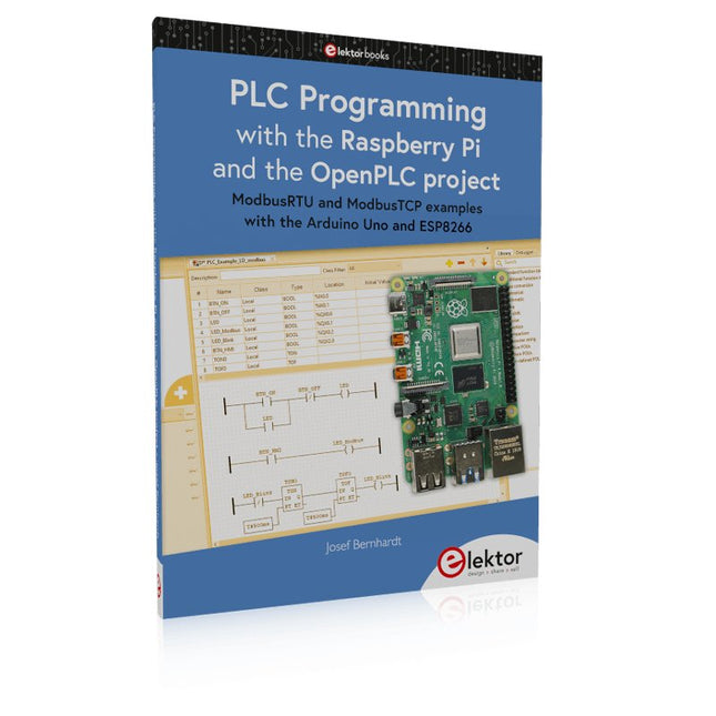
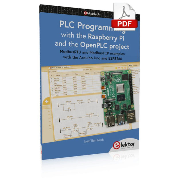
ModbusRTU and ModbusTCP examples with the Arduino Uno and ESP8266
Introduction to PLC programming with OpenPLC, the first fully open source Programmable Logic Controller on the Raspberry Pi, and Modbus examples with Arduino Uno and ESP8266
PLC programming is very common in industry and home automation. This book describes how the Raspberry Pi 4 can be used as a Programmable Logic Controller. Before taking you into the programming, the author starts with the software installation on the Raspberry Pi and the PLC editor on the PC, followed by a description of the hardware.
You'll then find interesting examples in the different programming languages complying with the IEC 61131-3 standard. This manual also explains in detail how to use the PLC editor and how to load and execute the programs on the Raspberry Pi. All IEC languages are explained with examples, starting with LD (Ladder Diagram) over ST (Structured Control Language) to SFC (Special Function Chart). All examples can be downloaded from the author's website.
Networking gets thorough attention too. The Arduino Uno and the ESP8266 are programmed as ModbusRTU or ModbusTCP modules to get access to external peripherals, reading sensors and switching electrical loads. I/O circuits complying with the 24 V industry standard may also be of interest for the reader.
The book ends with an overview of commands for ST and LD. After reading the book, the reader will be able to create his own controllers with the Raspberry Pi.
This book is for people who want to understand how AC drives (also known as inverter drives) work and how they are used in industry by showing mainly the practical design and application of drives.
The key principles of power electronics are described and presented in a simple way, as are the basics of both DC and AC motors. The different parts of an AC drive are explained, together with the theoretical background and the practical design issues such as cooling and protection.
An important part of the book gives details of the features and functions often found in AC drives and gives practical advice on how and where to use these. Also described is future drive technology, including a matrix inverter.
The mathematics is kept to an essential minimum. Some basic understanding of mechanical and electrical theory is presumed, and a basic knowledge of single andthree phase AC systems would be useful.
Anyone who uses or installs drives, or is just interested in how these powerful electronic products operate and control modern industry, will find this book fascinating and informative.
Easy and Affordable Digital Signal ProcessingThe aim of this book is to teach the basic principles of Digital Signal Processing (DSP) and to introduce it from a practical point of view using the bare minimum of mathematics. Only the basic level of discrete-time systems theory is given, sufficient to implement DSP applications in real time. The practical implementations are described in real time using the highly popular ESP32 DevKitC microcontroller development board. With the low cost and extremely popular ESP32 microcontroller, you should be able to design elementary DSP projects with sampling frequencies within the audio range. All programming is done using the popular Arduino IDE in conjunction with the C language compiler.After laying a solid foundation of DSP theory and pertinent discussions on the main DSP software tools on the market, the book presents the following audio-based sound and DSP projects:
Using an I²S-based digital microphone to capture audio sound
Using an I²S-based class-D audio amplifier and speaker
Playing MP3 music stored on an SD card through an I²S-based amplifier and speaker
Playing MP3 music files stored in ESP32 flash memory through an I²S-based amplifier and speaker
Mono and stereo Internet radio with I²S-based amplifiers and speakers
Text-to-speech output with an I²S-based amplifier and speaker
Using the volume control in I²S-based amplifier and speaker systems
A speaking event counter with an I²S-based amplifier and speaker
An adjustable sinewave generator with I²S-based amplifier and speaker
Using the Pmod I²S2 24-bit fast ADC/DAC module
Digital low-pass and band-pass real-time FIR filter design with external and internal A/D and D/A conversion
Digital low-pass and band-pass real-time IIR filter design with external and internal A/D and D/A conversion
Fast Fourier Transforms (FFT)
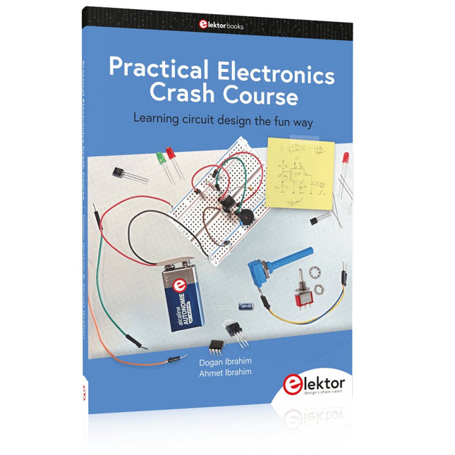
Learning circuit design the fun way
Welcome to the world of electronics!
Getting started in electronics is not as difficult as you may think. Using this book, you will explore and learn the most important electrical and electronics engineering concepts in a fun way by doing various experiments and by simulating circuits. It will teach you electronics practically without getting into complex technical jargon and long calculations. As a result, you will be creating your own projects soon.
No prior knowledge of electronics is required, only some basic algebra is used in a few simple calculations. Many tested and working projects and simulations are presented to familiarise yourself with the construction of electronic circuits. Circuit simulation is introduced at an early stage to enable you to experiment with circuits easily without breaking anything.
You will learn:
The concepts of voltage, current, and power
AC and DC
Basic lamp circuits with switches
Passive components: resistors, capacitors & inductors
RC & RCL circuits
Electromagnetism
Loudspeakers, relays, buzzers, and transformers
Active components: diodes & LEDs, bipolar transistors & MOSFETs
Transistor-based switching circuits
Optocoupler circuits
Astable & monostable multivibrators
Using the 555 timer IC
The operational amplifier
Digital logic
Advanced examples: amplifiers, oscillators, filters, and sensors
Test and measurement tools
Microcontrollers: Arduino UNO, ESP32, Raspberry Pi Pico, and Raspberry Pi
Reading datasheets and best practices for selecting components
EMC & EMI and norms & regulations
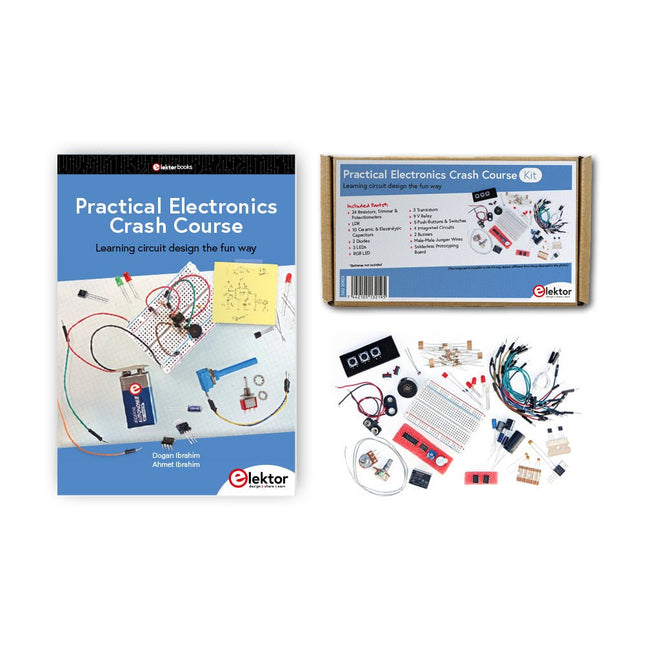
Beginnen met elektronica is niet zo moeilijk als je misschien denkt. Met deze bundel (boek + kit) kun je de belangrijkste concepten van elektrotechniek en elektronica op een leuke manier verkennen en leren door verschillende experimenten uit te voeren. Je leert elektronica op een praktische manier zonder ingewikkeld technisch jargon en lange berekeningen. Het resultaat is dat je snel je eigen projecten zult maken.
Deze kit bevat de onderdelen die nodig zijn om de meeste gedetailleerde voorbeelden uit het boek op een breadboard te bouwen en in het echt uit te proberen.
De kit kan natuurlijk ook zonder het boek gebruikt worden om andere schakelingen te bouwen en je eigen experimenten te doen.
Inhoud van de kit
1x 39 Ω, 1 W weerstand
1x 47 Ω weerstand
1x 180 Ω weerstand
1x 330 Ω weerstand
3x 1 kΩ weerstand
1x 2,2 kΩ weerstand
1x 3,9 kΩ weerstand
1x 6,8 kΩ weerstand
1x 10 kΩ weerstand
1x 15 kΩ weerstand
1x 22 kΩ weerstand
1x 33 kΩ weerstand
1x 47 kΩ weerstand
1x 56 kΩ weerstand
1x 82 kΩ weerstand
1x 120 kΩ weerstand
1x 680 kΩ weerstand
2x 100 kΩ weerstand
1x 10 kΩ-trimmer
1x 10 kΩ lineaire potentiometer
1x 100 kΩ lineaire potentiometer
1x LDR
1x 1 nF keramische condensator
2x 10 nF keramische condensator
1x 100 nF keramische condensator
1x 1 µF, 25 V aluminium elektrolytische condensator
2x 10 µF, 25 V aluminium elektrolytische condensator
1x 100 µF, 25 V aluminium elektrolytische condensator
1x 470 µF, 25 V aluminium elektrolytische condensator
1x 1000 µF, 25 V aluminium elektrolytische condensator
1x RGB-LED, gemeenschappelijke kathode (CC)
1x 1N4148 kleine signaaldiode
1x 1N4733A 5,1 V, 1 W zenerdiode
3x LED, rood
2x BC337 NPN-transistor
1x IRFZ44N N-kanaal MOSFET
2x NE555-timer
1x LM393-vergelijker
1x 74HCT08 quad EN-poort
3x Tactiele schakelaar
2x SPDT-schakelaar
1x relais, SPDT, 9 VDC
1x Actieve zoemer
1x Passieve zoemer
50 cm massieve draad, 16 AWG, zonder mantel
2x PP3 9 V-batterijclip
1x Broodplank
20x verbindingsdraad
Deze bundel bevat:
Practical Electronics Crash Course Kit (t.w.v. € 45)
Boek: Practical Electronics Crash Course (normale prijs: € 45)
Learning circuit design the fun way
Welcome to the world of electronics!
Getting started in electronics is not as difficult as you may think. Using this book, you will explore and learn the most important electrical and electronics engineering concepts in a fun way by doing various experiments and by simulating circuits. It will teach you electronics practically without getting into complex technical jargon and long calculations. As a result, you will be creating your own projects soon.
No prior knowledge of electronics is required, only some basic algebra is used in a few simple calculations. Many tested and working projects and simulations are presented to familiarise yourself with the construction of electronic circuits. Circuit simulation is introduced at an early stage to enable you to experiment with circuits easily without breaking anything.
You will learn:
The concepts of voltage, current, and power
AC and DC
Basic lamp circuits with switches
Passive components: resistors, capacitors & inductors
RC & RCL circuits
Electromagnetism
Loudspeakers, relays, buzzers, and transformers
Active components: diodes & LEDs, bipolar transistors & MOSFETs
Transistor-based switching circuits
Optocoupler circuits
Astable & monostable multivibrators
Using the 555 timer IC
The operational amplifier
Digital logic
Advanced examples: amplifiers, oscillators, filters, and sensors
Test and measurement tools
Microcontrollers: Arduino UNO, ESP32, Raspberry Pi Pico, and Raspberry Pi
Reading datasheets and best practices for selecting components
EMC & EMI and norms & regulations
From Simple Ciphers to Secure Systems
Understanding how to apply cryptography on modern microcontrollers is essential for building secure, reliable, and trustworthy systems. This book explains cryptography in the context of embedded hardware, from classical ciphers that illustrate core principles to modern techniques such as AES for practical high-security applications.
By combining mathematical theory with real-world microcontroller implementations, readers learn not only how cryptography works, but also how to implement it effectively on systems with limited processing power and memory. The book is intended for students starting out in cryptography, hobbyists securing personal projects, and engineers looking for a structured guide to embedded security.
The book covers these key topics in applied cryptography:
Classical ciphers on Arduino Uno and Raspberry Pi Pico, with full programs: Spartan Scytale, Hebrew Atbash, Caesar, ROT13, Alberti Disk, Vigenère, Affine, Polybius, Playfair, Beaufort, Ottoman Codebook, and One-Time Pad.
Hacking classical ciphers using microcontrollers, with examples.
Pseudo-random (PRNG) and true random number generation (TRNG) on microcontrollers.
Symmetric-key cryptography with full programs: DES and AES-128/256.
Memory and speed constraints of cryptography on microcontrollers.
Asymmetric cryptography: public/private keys, digital signatures, key distribution and derivation (KDF), RSA, and SHA-256 implementations.
A complete secure communication program using RSA and AES-256.
A glossary of commonly used cryptography terms.
Practical Low-Cost Methods for Reliable PCB Production
This book explains how to carry out reliable SMD assembly using affordable tools and small-scale equipment. It follows the complete workflow step by step, including tool selection, solder paste handling, stencil use, component placement, reflow methods, inspection, and rework.
The focus is on bench-level and small-lab production rather than industrial assembly lines. It shows practical methods for building single and double-sided SMD boards with repeatable results.
Topics include solder paste and flux, temperature profiles, hot air and hotplate techniques, small reflow ovens, inspection methods, and defect correction. Checklists and example workflows are included to help reduce errors and improve consistency.
Key features:
Tools and supplies for SMD assembly and rework
Solder paste types, storage, and handling
Stencils and paste application methods
Pick and place workflow and component orientation
Temperature profiles and reflow methods
Hot air, hotplate, and reflow oven processes
Inspection and quality control
Common defects such as tombstoning and solder bridges
Practical rework and component replacement
Bench-level professional workflows and checklists
This book is designed as a practical bench reference for anyone who wants to assemble and troubleshoot their own SMD boards with reliable results.
Het boek Programmeerbare Logica neemt je mee op een ontdekkingstocht door de wereld van de digitale elektronica. Na het leggen van een grondige basis is er uitgebreid aandacht voor het maken van logische circuits. Auteur Vincent Himpe toont o.a. hoe je met bestaande bouwstenen logische elektronica systemen maakt. Hij laat verder zien hoe je om gaat met de interfacing met de buitenwereld. Hierbij komen stroomvoorziening, bord layout en beveiliging uitvoerig aan bod.Moderne logische systemen zijn zo complex dat het ontwerpen met kleine bouwstenen zoals losse poortjes, flipflops en tellers een haast onbegonnen zaak geworden is. Daarom gaat Himpe in de tweede helft van het boek in op de programmeerbare logica zoals CPLD en FPGA. Hij belicht een ontwerpmethode waarmee je snel de brug slaat tussen het klassieke ontwerp en het ontwerp in FPGA.Naast schematisch ontwerp komt ook het ontwerpen met synthesetalen zoals Verilog en VHDL aan de orde. Ter afsluiting wordt een project (een klok met alarmfunctie) geïmplementeerd in Verilog en VHDL.Ook het fysieke ontwerp met deze logische componenten komt aan bod. Hoe programmeer je deze en wat zijn de randvoorwaarden zoals stroomvoorziening en signaalconditionering. De inhoud van het boek is 'state of the art'. En alles wat besproken wordt is direct implementeerbaar met de gratis ontwikkelomgeving Quartus van Altera.Over de auteur:Vincent Himpe (B) leeft sinds 2005 in San Jose – hartje Silicon Valley – en werkt aan de ontwikkeling van nieuwe harddisktechnologie en de chips.Himpe heeft meerdere patenten en over de jaren verschillende artikelen gepubliceerd in onder andere IMeko / TSCC, The Journal of Computer Standards AND Interfaces, Elektor en EDN. Hij is ook auteur van de bestseller 'Visual Basic for electronic engineering applications' uitgegeven door Elektor.
Programming the Finite State Machine with 8-Bit PICs in Assembly and C
Andrew Pratt provides a detailed introduction to programming PIC microcontrollers, as well as a thorough overview of the Finite State Machine (FSM) approach to programming. Most of the book uses assembly programming, but do not be deterred. The FSM gives a structure to a program, making it easy to plan, write, and modify. The last two chapters introduce programming in C, so you can make a direct comparison between the two techniques. The book references the relevant parts of the Microchip datasheet as familiarity with it is the best way to discover detailed information.
This book is aimed at Microsoft Windows and Linux users. To keep your costs to a minimum and to simplify the toolchain, specific applications are provided as a free download to enable you to use an FTDI serial lead as the programmer. The assembler used is the open-source "gpasm". All programming can be done in a text editor. There are detailed instructions on how to perform the necessary installations on Windows, Linux Debian, and derivatives such as Ubuntu and Fedora. For programming in C, Microchip's XC8 compiler is used from the command line. In addition to the programming applications, two serial read and serial write applications can be used for communicating with the PICs from a computer.
A voltmeter project including practical instructions on building a circuit board from scratch is included. All theory is covered beforehand, including how to do integer arithmetic in assembly.
Two PICs are covered: the PIC12F1822 and the PIC16F1823. Both can run at 32 MHz with an internal oscillator. You do not need to buy a factory-made development board and programmer. With relatively inexpensive parts including a serial lead, microcontroller, a few resistors, and LEDs, you can get started exploring embedded programming.
Links
Updated Programmer
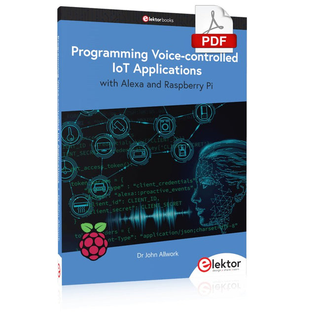
Learn programming for Alexa devices, extend it to smart home devices and control the Raspberry Pi
The book is split into two parts: the first part covers creating Alexa skills and the second part, designing Internet of Things and Smart Home devices using a Raspberry Pi.
The first chapters describe the process of Alexa communication, opening an Amazon account and creating a skill for free. The operation of an Alexa skill and terminology such as utterances, intents, slots, and conversations are explained. Debugging your code, saving user data between sessions, S3 data storage and Dynamo DB database are discussed.
In-skill purchasing, enabling users to buy items for your skill as well as certification and publication is outlined. Creating skills using AWS Lambda and ASK CLI is covered, along with the Visual Studio code editor and local debugging. Also covered is the process of designing skills for visual displays and interactive touch designs using Alexa Presentation Language.
The second half of the book starts by creating a Raspberry Pi IoT 'thing' to control a robot from your Alexa device. This covers security issues and methods of sending and receiving MQTT messages between an Alexa device and the Raspberry Pi.
Creating a smart home device is described including forming a security profile, linking with Amazon, and writing a Lambda function that gets triggered by an Alexa skill. Device discovery and on/off control is demonstrated.
Next, readers discover how to control a smart home Raspberry Pi display from an Alexa skill using Simple Queue Service (SQS) messaging to switch the display on and off or change the color.
A node-RED design is discussed from the basic user interface right up to configuring MQTT nodes. MQTT messages sent from a user are displayed on a Raspberry Pi.
A chapter discusses sending a proactive notification such as a weather alert from a Raspberry Pi to an Alexa device. The book concludes by explaining how to create Raspberry Pi as a stand-alone Alexa device.
Design IoT Projects with Raspberry Pi, Arduino and ESP32 The Internet of Things (IoT) is becoming a major application area for embedded systems. As a result, more and more people are becoming interested in learning about embedded design and programming. Technical colleges and universities are moving away from legacy 8 and 16-bit microcontrollers and are introducing 32-bit embedded microcontrollers to their curriculums. Many IoT applications demand precision, high processing power, and low power consumption. Produced by IBM, Node-RED is an open-source visual editor for wiring the Internet of Things. Node-RED comes with a large number of nodes to handle a multitude of tasks. The required nodes are selected and joined together to perform a particular task. Node-RED is based on flow type programming where nodes are configured and joined together to form an application program. There are nodes for performing complex tasks, including web access, Twitter, E-mail, HTTP, Bluetooth, MQTT, controlling GPIO ports, etc. One particularly nice aspect of Node-RED is that the programmer does not need to learn how to write complex programs. For example, an email can be sent by simply joining nodes together and writing only a few lines of code. The aim of this book is to teach how Node-RED can be used in projects. The main hardware platform used with most of the projects in this book is Raspberry Pi 4. Chapters are included to show how Node-RED can be also be used with Arduino Uno, ESP32 DevKitC, and the ESP8266 NodeMCU microcontroller development boards.
STM32 Nucleo family of processors are manufactured by STMicroelectronics. These are low-cost ARM microcontroller development boards. This book is about developing projects using the popular Nucleo development board. In the early chapters of the book, the architecture of the Nucleo family is briefly described.
Software development tools that can be used with the Nucleo boards such as the Mbed, Keil MDK, TrueSTUDIO, and the System Workbench are described briefly in later Chapters.
The book covers many projects using most features of the STM32 Nucleo development boards where the full software listings for Mbed and System Workbench are given for every project. The projects range from simple flashing LEDs to more complex projects using modules and devices such as GPIO, ADC, DAC, I²C, LCD, analog inputs and others.
In addition, several projects are given using the Nucleo Expansion Boards, including popular expansion boards such as solid-state relay, MEMS and environmental sensors, DC motor driver, Wi-Fi, and stepper motor driver.
These Expansion Boards plug on top of the Nucleo development boards and simplify the task of project development considerably.
Features of this book
Learn the architecture of the STM32 microcontrollers
Learn how to use the Nucleo development board in projects using Mbed and System Workbench Toolchains
Learn how to use the Nucleo Expansion Boards with the Nucleo development boards
Update
The Mbed compiler has been replaced with two software packages: The Mbed Studio and Keil Studio Cloud. Both of these software packages are free of charge and are available on the Internet. If you need assistance using the Keil Studio Cloud, please download the Guide below.
Learn to use Python productively in real-life scenarios at work and in everyday life
If you have mastered the basics of Python and are wanting to explore the language in more depth, this book is for you. By means of concrete examples used in different applications, the book illustrates many aspects of programming (e.g. algorithms, recursion, data structures) and helps problem-solving strategies. Including general ideas and solutions, the specifics of Python and how these can be practically applied are discussed.
Python 3 for Science and Engineering Applications includes:
practical and goal-oriented learning
basic Python techniques
modern Python 3.6+ including comprehensions, decorators and generators
complete code available online
more than 40 exercises, solutions documented online
no additional packages or installation required, 100% pure
Python Topics cover:
identifying large prime numbers and computing Pi
writing and understanding recursive functions with memorisation
computing in parallel and utilising all system cores
processing text data and encrypting messages
comprehending backtracking and solving Sudokus
analysing and simulating games of chance to develop optimal winning strategies
handling genetic code and generating extremely long palindromes
Downloads
Software
This is the second edition of a book aimed at engineers, scientists, and hobbyists who want to interface PCs with hardware projects using graphical user interfaces. Desktop and web-based applications are covered.
The programming language used is Python 3, which is one of the most popular languages around: speed of programming being a key feature. The book has been revised and updated with an emphasis on getting the user to produce practical designs with ease – a text editor is all that is required to produce Python programs.
Hardware interfacing is achieved using an Arduino Uno as a remote slave. A full description and source code of the communication interface is given in the book. The slave provides digital and analog input and outputs. Multiple Unos can be included in one project with all control code written in Python and running on a PC One project involves a PIC microcontroller with the code provided that can be loaded into the PIC using the Uno.
The web applications and server are all implemented in Python, allowing you to access your electronic hardware over the Internet. The Raspberry Pi computer can be used as your web server. An introductory chapter is provided to get you started with using Linux.
The book is written for use with Debian or variations including Mint or Ubuntu. All of the programs in the book are freely available, ready to use and experiment with by way of a download from Elektor.
De Quick 861DW is een geavanceerd Hot Air Rework Station met een verhittingsvermogen van 1000 W. Hij is ontworpen voor het professioneel solderen van elektronische SMD-componenten met behulp van loodvrij soldeer.
Kenmerken
Drie programmeerbare kanalen CH1, CH2 en CH3 (voor verschillend luchtvolume en temperatuur).
Wachtwoordbeveiliging en een button lock functie.
Een magnetische schakelaar in de houder kan het station automatisch in de slaapstand zetten wanneer hij niet in gebruik is.
Eenvoudige real-time bediening, automatische sleep functie beschikbaar, parameters kunnen in de sleep modus worden ingesteld.
Closed loop sensor, temperatuur geregeld door een micro computer; zero trigger, hoog vermogen, snelle temperatuurstijging, temperatuur kan eenvoudig en nauwkeurig worden aangepast, niet beïnvloed door de luchtstroom.
Borstelloze vortex ventilator, groot bereik van de instelbare luchtstroom, geschikt voor vele toepassingen.
Automatische koelfunctie beschikbaar, keramische verwarming met lange levensduur.
Specificaties
Vermogen
1000 W
Werkspanning
AC 200~240 V
Temperatuurbereik
100-500°C
Luchtvolume
1-120 class
Luchtstroom
50 l/min (max)
Afmetingen
188 x 245 x 135 mm
Gewicht
3,65 kg
Downloads
Handleiding