Programmers & Debuggers

10 producten


  • Raspberry Pi Debug Probe

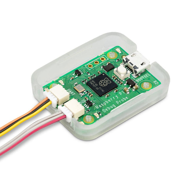
    Raspberry Pi Foundation Raspberry Pi Debug Probe

    The Raspberry Pi Debug Probe is an all-in-one USB-to-debug kit that provides all the necessary hardware and cables for easy, solderless, plug-and-play debugging. It features both a processor serial debug interface (by default the ARM Serial Wire Debug interface, but other interfaces can be supported) and an industry-standard UART interface. Both interfaces use the Raspberry Pi 3-pin debug connector. It is designed to make it easy to debug and program Raspberry Pi Pico and RP2040 with a range of host platforms including Windows, Mac, and typical Linux computers. While designed for use with Raspberry Pi products, the Debug Probe provides standard UART and CMSIS-DAP interfaces over USB, so it can also be used with other processors, or even just as a USB-to-UART cable. It works with OpenOCD and other tools that support CMSIS-DAP. The Debug Probe is based on Raspberry Pi Pico hardware and runs the open source Raspberry Pi Picoprobe software. The firmware is updated in the same way as Raspberry Pi Pico firmware, so it is easy to keep the unit up to date with the latest firmware, or to use custom firmware. Features USB to ARM Serial Wire Debug (SWD) port USB to UART bridge Compatible with the CMSIS-DAP standard Works with OpenOCD and other tools supporting CMSIS-DAP Open source, easily upgradeable firmware Specifications Dimensions: 22 x 32 mm Nominal I/O voltage: 3.3 V Operating temperature: -20°C to +70°C Included 1x Raspberry Pi Debug Probe 1x Plastic case 1x USB cable 3x Debug cables 3-pin JST connector to 3-pin JST connector cable 3-pin JST connector to 0.1-inch header (female) 3-pin JST connector to 0.1-inch header (male) Downloads Datasheet 3-pin Debug Connector Schematics Diagram

    € 14,95

    Leden identiek

  • I²CDriver

    Excamera Labs I²CDriver

    Niet op voorraad

    I²C is ubiquitous, you can find it in your phone, in embedded electronics, in all microcontrollers, Raspberry Pi and computer motherboards. It's applicable in a wide variety of cases, but the only downside is that it might be difficult to learn using it properly and to avoid painful debugging.This device makes it easier for you to understand what's going on inside, as I²CDriver has a clear logic-analyzer display of the signal lines plus a graphical decoding of the I²C traffic.In addition, it continuously displays an address map of all attached I²C devices, so as you connect a device, it lights up on the map.The current and voltage monitoring let you catch electrical problems early. The included color-coded wires make hookup quite easy; no pinout diagram is required. It includes a separate 3.3 V supply for your devices, a high-side current meter, and programmable pullup resistors for both I²C lines.Thanks to 3 I²C ports you can hook up multiple devices simultaneously without any effort. I²CDriver comes with software to control it from: a GUI the command-line C and C++ using a single source file Python 2 and 3, using a module You can control I²C hardware using the PC tools you’re familiar with and reduce the development time needed to get the device doing what you want it to.Calibrating devices like accelerometers, magnetometers, and gyroscopes is much simpler and faster when done directly on the PC through I²CDriver.Moreover, the built in display shows a heatmap of all active network nodes. So in an I²C network with multiple devices, you can see at a glance which ones are the most active.I²CDriver can dump all I²C traffic back to the PC. I²CDriver’s capture mode reliably records every bit to an exhaustive time-stamped log. This is really helpful for debug, analysis, and reverse-engineering. Supported formats include text, CSV, and VCD.Features Open hardware: the design, firmware and all tools are under BSD license Live display: shows you exactly what it’s doing all the time Fast transfer: sustained I²C transfers at 400 and 100 kHz USB power monitoring: USB line voltage monitor to detect supply problems, to 0.01 V Target power monitoring: target device high-side current measurement, to 5 mA I²C pullups: programmable I²C pullup resistors, with automatic tuning Three I²C ports: three identical I²C ports, each with power and I²C signals Jumpers: color coded jumpers included in each pledge level 3.3 output: output levels are 3.3 V, all are 5 V tolerant Supports all I²C features: 7- and 10-bit I²C addressing, clock stretching, bus arbitration Sturdy componentry: uses an FTDI USB serial adapter, and Silicon Labs automotive-grade EFM8 controller Usage reporting: reports uptime, temperature, and running CRC of all traffic Flexible control: GUI, command-line, C/C++, and Python 2/3 host software provided for Windows, Mac, and Linux Details Maximum power out current: up to 470 mA Device current: up to 25 mA Dimensions: 61 mm x 49 mm x 6 mm Computer interface: USB 2.0, micro USB connector Contents (I²CDriver Core) 1x I²CDriver 3x Set of hookup jumpers

    Niet op voorraad

    € 44,95

    Leden € 40,46

  • SPIDriver

    Excamera Labs SPIDriver

    2 reviews

    SPIDriver shows you what’s happening on the SPI bus in real time, so no more guessing about the bus state. Its purpose is to make understanding the functioning of SPI hardware more intuitive. It's useful if you're into debugging hardware or simply introduce a class to SPI for the first time.You can directly control LEDs and LCD displays just by having SPIDriver and you won't have to deal with microcontrollers. It's also a useful tool for examining, backing up and cloning an SPI flash as well as reading and writing SPI flash in circuit.SPIDriver is also applicable if you want to drive, test and evaluate different displays.With the help of current and voltage monitoring you'll be able to detect electrical problems at early stages. Thanks to the included color coded wires you can hook SPIDriver up without much effort; no pinout diagram required. It includes 3.3 V and 5 V supplies for your device, plus a high-side current meter.SPIDriver comes with software to control it from: a GUI the command-line C and C++ using a single source file Python 2 and 3, using a module Technical features Live display shows you exactly what it’s doing all the time Sustained SPI transfers at 500 Kbps USB line voltage monitor to detect supply problems, to 0.01 V Target device high-side current measurement, to 5 mA Two auxiliary output signals, A and B Two dedicated power outlines: of 3.3 V and 5 V All signals color coded to match jumper colors All signals are 3.3 V, and are 5 V tolerant Uses an FTDI USB serial adapter, and Silicon Labs automotive-grade EFM8 controller Also reports uptime, temperature, and running CRC of all traffic All sensors and signals controlled using a simple serial protocol GUI, command-line, C/C++, and Python 2/3 host software provided for Windows, Mac, and Linux Details Maximum power out current: up to 470 mA Signal current: up to 10 mA Device current: up to 25 mA Dimensions: 61 mm x 49 mm x 6 mm Interface: USB 2.0, micro USB connector Contents (SPIDriver Core) 1x SPIDriver 1x Set of hookup jumpers

    € 49,95

    Leden € 44,96

  • Black Magic Probe V2.3 – JTAG/SWD ARM Microcontroller Debugger

    1 Bit Squared Black Magic Probe V2.3 - JTAG/SWD ARM Microcontroller Debugger

    Black Magic Probe V2.3 is a JTAG and SWD Adapter with a built-in GDB server used for programming and debugging ARM Cortex MCUs. Its the best friend of any ARM microcontroller developer.All proceeds from BMP hardware sales go directly into the continued development, maintenance and support of the Open-Source Black Magic Debug project.Black Magic Probe gets rid of intermediate programs like OpenOCD or STLink server. This makes the operation faster and more reliable. You just open your GNU Debugger (GDB) and select the virtual com port offered by BMP23 as your extended remote target. For a full description and how-to visit the project website.Features Wide target IO voltage range support, 1.7 V up to 5 V, thanks to VREF referenced level shifters Power switch allowing supply of 3.3 V to the target through the VREF pin Standard ARM-Cortex 0.05' pitch 10pin debug connector Aux UART capable of up to 2 MBaud Small size (4 x 2 x 1 cm) (1.3 x 0.6 x 0.45'), saving space in your field kit and allowing the use of the debugger in very tight spaces and enclosures Jumpers allowing the connection of the UART TX/RX pins to the JTAG/SWD connector resulting in a 'Unified debug' connector TraceSWO UART, decoding hardware support 16 MByte on board flash AUX connector for accessories Mechanical layout allowing easier use of enclosures and mounting into bigger systems. For example: automated pogopin test equipment, automated Hardware In The Loop (HITL) Continous Integration (CI) systems Improved layout, allowing further improvement of the Black Magic Debug firmware reliability and speed using hardware protocol acceleration Included 1x Black Magic Probe Mini V2.3 (BMP23) 1x JTAG Ribbon Cable 1x 0.1' Header Serial Cable 1x 10-pin ARM Cortexto7-pin Adapter 1x UART 0.1' Cable Dimensions 70 x 17 mm (1.3 x 0.6 in) 3.6 g (0.128 oz)

    € 114,95

    Leden € 103,46

  • USB ISP-Programmer Stick for AVR

    USB ISP-Programmer Stick for AVR

    Niet op voorraad

    Functions Write and read FLASH memory Write and read EEPROM Write and read Fusebits Write and read lock bits Chip erase Read OSCCAL register Compatible with Atmel ATtiny ATtiny12, ATtiny13, ATtiny15, ATtiny2313, ATtiny24, ATtiny25, ATtiny26, ATtiny44, ATtiny45, ATtiny84, ATtiny85, Attiny86, ATtiny261, ATtiny461, ATtiny861 Atmel ATmega Atmega88, ATmega103, ATmega128, ATmega1280, ATmega1281, ATmega16, ATmega161, ATmega162, ATmega163, ATmega164, ATmega168, ATmega169, ATmega32, ATmega324, ATmega325, ATmega328, ATmega3250, ATmega329x, ATmega48, ATmega64, ATmega640, ATmega644, ATmega645, ATmega6450, ATmega649x, ATmega8, ATmega8515, ATmega8535 Other ATmel Controllers AT90CAN128, AT90PWM2, AT90PWM2B, AT90PWM3, AT90PWM3B, AT90USB162, AT90USB646, AT90USB647, AT90USB1286, AT90USB1287

    Niet op voorraad

    € 29,95

    Leden € 26,96

  •  -19% The ?Art Kit – USB to UART-TTL Adapter

    The μArt Kit - USB to UART-TTL Adapter

    µArt aims to solve common problems of existing UART adapters by covering all use cases with a single device, and offering a reliable and robust solution that you can just trust to work right. The μArt has all the pins and features to enable various applications, protections to withstand or even prevent faults, providing signal integrity, and measures to improve usability. You don't need to worry that a tiny mistake will lead to a damage of expensive connected devices. USB-UART converters are used during initial board bringup, for debugging and development, for flashing firmware, for exchanging operational data, for controlling peripherals, as service ports in the field, or as diagnostic interfaces during analysis. If you work or hack in the electronics engineering, computer engineering, or embedded systems fields, a UART adapter is most probably is one of your essential tools. The µART will be of value for a wide public, starting from newbies to experienced engineers. Industry professionals will value being able to depend on the μArt and being able to focus on their work without having to second-guess their tool. Hobbyists and students, who can make mistakes more easily, will like that the μArt isolates faults and prevents damage to surrounding equipment. You'll also find this device very useful in various applications together with Raspberry Pi, Arduino or Espressif. Moreover, the μArt supports non-standard and custom baudrates (such as 128000) so that you can use a fast and reliable setting for your MCU. Kenmerken Wide working voltage of 1.8 to 5.4 V, making it suitable for most projects, be it single-board computers, microcontrollers, FPGAs, or low-power electronics. RXD, TXD, DTR, RTS, and CTS. Usable not just for basic communication, but also for flashing various modules from Espressif and multiple Arduinos such as the Pro Mini, Fio, or Arduino Pro. Hardware handshaking allows for reliable high-speed UART. Non-standard baudrate support, so that you can use it with standard-clocked microcontrollers and still have a low error-rate.  Up to 3 Mbaud transfer speed, the highest in the industry. This is enough bandwidth to stream uncompressed high-quality stereo audio. Complete galvanic isolation, even for mains-level and higher voltages. Electrical current cannot flow between your computer and the other board. This provides safety for you and your computer, while also helping to keep noise levels down. Reverse polarity protection. The converter will survive even if you mix up the power pins. Over-current protection on IO pins. Made a false IO connection by mistake? Don’t worry, the μArt and your other board are both safe. Pullups on all inputs, so that disconnected pins don’t cause funny things like garbage random input, a ruined terminal app, or corrupt application state. Judicious filtering. Each IC in the converter is decoupled using multiple capacitors, both locally and in bulk. The USB signals and power are filtered, and sensitive pins are protected with RC networks. Multi-level ESD protection for all interfaces. ESD damage is tricky because things can seem to work for a while after an ESD event, and you don’t need visible sparks to have it. Voltage auto-sensing, meaning the converter will automatically use the correct voltage levels for UART communication. Cross-platform support, with readily available and mature drivers for Windows, Linux, MacOS, and more. Suitable for communicating with low-noise circuits, supported by the filters, the isolation, and careful layout. GPIO pins that you can control directly over USB, parallel to the UART lines. They can also be reconfigured in software for alternate functions (for example, TXDEN for RS-485). Four LEDs, each of different color to make them immediately distinguishable. One lights up if power is connected, two indicate RX/TX activity, while the last one is connected to a GPIO, giving you visual feedback about its state without special software on the host computer. Four-wall shrouded header protects against ESD from fingers and from shorts by dangling wires. Custom-designed case, professional and ergonomic, giving both mechanical and electrical protection, and a cool transparent-translucent look. Inbegrepen The μArt comes in a custom-designed plastic case by default and provides mechanical protection as well as adds to the electrical protection. Additionally, following cables are included: A high-quality Micro USB cable by KabelDirekt A split “squid” cable that mates with the μArt using a single connector (female ends) A ribbon jumper cable (male ends)

    € 79,95€ 64,95

    Leden identiek

  •  -20% Diamex EXA-Prog Package

    Diamex Diamex EXA-Prog Package

    EXA-Prog in housing EXA-Prog represents the new generation of ISP programmers, which are not limited to one specific microcontroller type, but support several different controller architectures and programming interfaces. Laser-cut plexiglass housing. Two built-in status LEDs signal the current state of the programmer. Features Function selection via DIP switch Signal level switchable, 3.3 V, 5 V Integrated high voltage generator for UPDI programming Automatic bit-rate adjustment in AVR-ISP mode Clock generator for AVR controller with fuse oscillator Button to reset the connected microcontroller 10-pin standard ISP connector Optional accessories: 10-pin to 6-pin adapter, ESP01 adapter Mini-USB connector for power supply and connection to PC Firmware can be updated via USB Windows PC tool for testing the signal levels at the programming port. Current consumption without microcontroller connected: approx. 30 mA Signal level at programming connector: 5 V (USB voltage) or 3.3 V Power supply for the external circuit: max. 300 mA (3.3 V), max. 500 mA (5 V) UPDI high voltage: approx. 12.3 V Weight: approx. 25 g Adapter 10-pin to 6-pin IS P and 6-pin UPDI The optimal solution for in-system programming (ISP) of AVR controllers. There are two different standards for the AVR-ISP interface, 6-pin and 10-pin. With this adapter kit, you can exchange the programming lines between both standards. For programming AVR-UPDI a 6-pin connector is also needed. This adapter supports 10-pin to 6-pin for AVR-ISP programming and 10-pin to 6-pin for AVR-UPDI programming. ESP adapter No buttons or switches are needed to activate the ESP bootloader. When ESPTOOL is used, the bootloader is automatically activated and the firmware is started after programming is complete. If another program is used that does not take over this control itself, the bootloader of the ESP can also be activated by a long press on the RESET button of the EXA-PROG and the firmware can be started by a short press after programming. AVR swivel lever High-quality module with swivel lever zero force socket for almost all AVR controllers in DIL package. No own board is required. DIL controllers are easy and fast to program. Can also be used for series production. The 10-pin ISP standard connector from Atmel is used. Additionally, pin 3 is designed as a clock connector if the controller is set to an external clock. 5x 10-pin ISP well connectors for AVR controller in DIL package Compatible with all signal levels Pin 3 for the clock generator High quality swing lever socket (zero force socket) for variable 4-18 mm pin spacing Included EXA-Prog in housing Adapter 10-pin to 6-pin ISP and 6-pin UPDI ESP adapter AVR swivel lever Mini-USB cable 10-pin connection cable 6-pin connection cable 6-pin jumper cable, male-female 6-pin jumper cable, female-female

    € 74,95€ 59,95

    Leden identiek

  • Microchip MPLAB PICkit 5 in-circuit debugger/programmer

    Microchip Microchip MPLAB PICkit 5 in-circuit debugger/programmer

    De MPLAB PICkit 5 in-circuit debugger/programmer maakt snelle prototyping en draagbare productieklare programmering mogelijk voor alle Microchip apparaten, inclusief PIC-microcontrollers (MCU's) en dsPIC Digital Signal Controllers (DSC's), AVR- en SAM-apparaten, en op Arm Cortex gebaseerde microprocessors (MPU's). Hij werkt samen met de MPLAB X Integrated Development Environment (IDE), en biedt daarmee een krachtige en gebruiksvriendelijke grafische gebruikersinterface (GUI) voor foutopsporing en programmering. Als alternatief kan de MPLAB PICkit 5 in-circuit debugger/programmer ook stand-alone worden gebruikt met de MPLAB Programmer-to-Go (PTG) mobiele app, zodat u via Bluetooth verbinding kunt maken met dit tool vanaf uw smartphone. Met stand-alone programmeerfuncties, die toegankelijk zijn vanaf uw smartphone, is de MPLAB PICkit 5 in-circuit debugger/programmer een veelzijdige programmeerhulp waarmee u uw oplossing kunt prototypen en debuggen. Daarna kunt u de stekker uit het stopcontact halen en het apparaat meenemen om de oplossing ter plaatse te implementeren. Kenmerken Verbeterde ondersteuning voor Programmer-to-Go (PTG) met de MPLAB PTG mobiele app Maak draadloos verbinding vanaf uw smartphone via Bluetooth Kies uit meerdere opgeslagen programma-images op de SD-kaart Start het programmeren vanuit de app of door op het logo te drukken Lever 150 mA voeding aan het aangesloten apparaat Optie om zelf te worden gevoed door het aangesloten apparaat (2,7 V tot 5 V) Vereenvoudig uw werksituatie USB-C connector en kabel Geen externe voeding nodig wanneer het apparaat wordt gevoed door high-speed USB 2.0 Gebruik de achtpins enkelvoudige in-line header Ondersteunt JTAG, SWD, UART VCP Adapterkaart maakt het gebruik van standaard connectoren voor JTAG, SWD, ICSP en AVR mogelijk Verlaag kosten Functies en prestaties tegen een fractie van de kosten van vergelijkbare debuggers/programmers Inbegrepen 1x MPLAB PICkit 5 in-circuit debugger/programmer 1x USB-A naar USB-C kabel 2x MPLAB PICkit 5 in-circuit debugger/programmer (stickers) Downloads Gebruikershandleiding MPLAB X IDE

    € 164,95

    Leden € 148,46

  • Microchip MPLAB ICD 5 in-circuit debugger/programmer

    Microchip Microchip MPLAB ICD 5 in-circuit debugger/programmer

    De MPLAB ICD 5 in-circuit debugger/programmer biedt geavanceerde connectiviteits- en voedingsopties voor ontwikkelaars van schakelingen die gebaseerd zijn op PIC-, AVR- en SAM-apparaten en dsPIC Digital Signal Controllers (DSC's). Hij kan debuggen en programmeren met de krachtige en gebruiksvriendelijke grafische gebruikersinterface van de MPLAB X Integrated Development Environment (IDE). Dit tool van de nieuwste generatie biedt een verscheidenheid aan mogelijkheden en functies die je normaal gesproken alleen in duurdere producten vindt, en die de ontwikkeltijd versnellen en de foutopsporingstijd verkorten. Met zijn ondersteuning voor Fast Ethernet connectiviteit en Power over Ethernet Plus (PoE+) zorgt de MPLAB ICD 5 Debugger/Programmer voor flexibiliteit en gemak bij het ontwikkelen op afstand, terwijl de toepassing wordt geïsoleerd van omgevingsinvloeden. Of u nu een ervaren ontwikkelaar of nog maar net begonnen bent: de MPLAB ICD 5 In-Circuit Debugger/Programmer versnelt het ontwikkelproces, en helpt u om uw ontwerpen naar een hoger niveau te tillen. Kenmerken Een USB-C interface maakt het makkelijk om verbinding te maken met een pc De high-speed USB 2.0 host-pc-interface ondersteunt snelheden tot 480 Mbps voor snelle gegevensoverdracht PoE+ (IEEE 802.3at) biedt een praktische en flexibele optie om de debugger/programmer van stroom te voorzien, en stroom te leveren aan het aangesloten apparaat Fast Ethernet connectiviteit ondersteunt snelheden tot 100 Mbps Wired/DHCP/APIAP IP adressering Statische IP adressering Kan verbinding maken met meerdere apparaten met behulp van een RJ11 of RJ45 modulaire kabel Inclusief adapterkaart die ondersteuning biedt voor JTAG-, SWD-, ICSP- en AVR MCU-protocollen Professionele veiligheidsopties, en ondersteuning voor apparaten van 1,2 V tot 5,5 V Voedt het aangesloten apparaat veilig met maximaal 1 A met behulp van de PoE voeding, of een PC met een USB-C connector Ontvangt feedback van de debugger indien een externe voeding nodig is voor het aangesloten apparaat CE en RoHS compatibel, voldoet aan de industrienormen Geavanceerde traceermogelijkheden Ondersteuning voor geïnstrumenteerde tracering via de Arm Serial Wire Debug (SWD) interface Monitoring van de voeding Stelt u in staat om het stroomverbruik van uw ontwerp te optimaliseren Legt voedingsdata vast, zoals stroom- en spanningswaarden Werkt met MPLAB Data Visualizer, die voedingsgegevens grafisch analyseert Data gateway interfaces UART via Windows Virtual COM Port (VCP) Voeding Continuous Integration / Continuous Delivery (CI/CD) ondersteuning Kan via Ethernet worden geïmplementeerd met behulp van hardware in de loop Kan werken met de CI/CD wizard beschikbaar met MPLAB X IDE v6.10 en hoger om het systeem in te stellen met behulp van Jenkins en Docker Krachtige foutopsporing Krachtige debugging met de MPLAB X IDE Meerdere breekpoints, stopwatch en debugging van broncodebestanden Selecteerbare pull-up/pull-down optie richting de doelinterface in de editor van de MPLAB X IDE voor snelle programma-aanpassing en foutopsporing High-speed programmering Snel herladen van de firmware voor snelle foutopsporing en herprogrammering binnen het ontwerp Debuggingsnelheid kan worden aangepast voor een geoptimaliseerde programmering Inbegrepen MPLAB ICD 5 in-circuit debugger en programmer USB-C kabel Adapter kit Downloads Gebruikershandleiding Datasheet

    € 649,00

    Leden € 584,10

  • Sipeed RV-Debugger Plus JTAG + UART BL702

    Seeed Studio Sipeed RV-Debugger Plus JTAG + UART BL702

    Niet op voorraad

    BL702 is a highly integrated BLE and Zigbee combo chipset for IoT applications, contains 32-bit RISC-V CPU with FPU, frequency up to 144MHz, with 132KB RAM and 192 KB ROM, 1Kb eFuse, 512KB embedded Flash, USB2.0 FS device interface, and many other features. The firmware implement is inspired by 'open-ec', implemented by Sipeed teams and community developers. The firmware emulates an FT2232D device, default implement a JTAG+UART debugger, and can be implemented as a Dual-Serial Port debugger, a Bluetooth debugger, etc.

    Niet op voorraad

    € 8,95

    Leden € 8,06

Login

Wachtwoord vergeten?

Heb je nog geen account?
Maak gratis een account aan en geniet van vele voordelen.