De LoRa-E5 Development Kit is een gemakkelijk te gebruiken compacte ontwikkel-toolset waarmee je de krachtige eigenschappen van de LoRa-E5 STM32WLE5JC kunt ontdekken. Het bestaat uit een LoRa-E5 Dev Board, een antenne (EU868), een USB type C kabel, en een 2-AA 3 V batterijhouder.Het LoRa-E5 Dev Board is uitgerust met de LoRa-E5 STM32WLE5JC module, die de eerste combinatie is van LoRa RF en MCU chip in een kleine enkelvoudige chip, en is FCC en CE gecertificeerd. Hij is voorzien van een ARM Cortex-M4 kern en Semtech SX126X LoRa chip, ondersteunt zowel LoRaWAN als LoRa protocol op de wereldwijde frequentie en (G)FSK, BPSK, (G)MSK, en LoRa modulaties.
Het LoRa-E5 ontwikkelingsboard heeft een zeer groot zendbereik, een extreem laag stroomverbruik en gebruiksvriendelijke interfaces.
Het LoRa-E5 Dev Board heeft een long range zendbereik van LoRa-E5 tot 10 km in een open gebied. Het stroomverbruik van de on-board LoRa-E5 modules in sleep mode is slechts 2.1 µA (WOR mode). Hij is ontworpen volgens industriële normen met een brede werktemperatuur van -40? ~ 85?, hoge gevoeligheid tussen -116.5 dBm ~ -136 dBm, en uitgangsvermogen tot +20.8 dBm bij 3.3 V.
Het LoRa-E5 Dev board heeft ook veel interfaces. Om de volledige functionaliteit van de LoRa-E5 module te kunnen gebruiken heeft het LoRa-E5 Dev Board alle 28 pinnen van LoRa-E5 bedraad en voorziet het van vele interfaces waaronder Grove connectoren, RS-485 terminal, male/female pin headers waarmee je sensoren en modules met verschillende connectoren en gegevensprotocollen kunt aansluiten, zodat je tijd bespaart bij het solderen van draden. Je kunt het board ook gemakkelijk van stroom voorzien door de batterijhouder aan te sluiten met 2-AA batterijen, zodat je het tijdelijk kunt gebruiken zonder externe stroombron. Het is een gebruiksvriendelijke printplaat om gemakkelijk te testen en snel prototypes te maken.
Specificaties
Afmetingen
LoRa-E5 Dev Board: 85.6 x 54 mm
Voedingsspanning
3-5 V (Battery) / 5 V (USB-C)
Uitgangsstroom
EN 3V3 / 5 V
Uitgangsvermogen
Tot +20.8 dBm bij 3.3 V
Frequentie
EU868
Protocol
LoRaWAN
Gevoeligheid
-116.5 dBm ~ -136 dBm
Interfaces
USB Type C / JST2.0 / 3x Grove (2x I²C/1x UART) / RS485 / SMA-K / IPEX
Modulatie
LoRa, (G)FSK, (G)MSK, BPSK
Werktemperatuur
-40? ~ 85?
Stroomverbruik
LoRa-E5 module sleep current slechts 2.1 uA (WOR mode)
Inbegrepen
1x LoRa-E5 Dev Board
1x Antenne (EU868)
1x USB Type C kabel (20 cm)
1x 2-AA 3 V Batterijhouder
Features Plug & Play (No driver required), compatible with Windows 10/8/7, Mac, Linux and Android that support OTG. Voice Pick-up device, Far-field voice pick-up up to 5m and supports 360° pick-up pattern Acoustic algorithms implemented: DOA(Direction of Arrival), AEC(Automatic Echo Cancellation), AGC(Automatic Gain Control), NS(Noise Suppression) Built-in audio jack, which allows for plugging in headphones or speakers (speaker not included) Applications Voice pick-up device Home/Office automation device In-car voice assistant Healthcare device Voice interaction robot Other applications Technical Specifications XVF-3000 from XMOS 4 High-Performance Digital Microphones Supports Far-field Voice Capture Speech Algorithms On-Chip 12 Programmable RGB LED Indicators Microphones: MEMS MSM261D4030H1CPM Sensitivity: -26 dBFS (Omnidirectional) Acoustic Overload Point: 120 dB SPL SNR: 63 dB Power Supply: 5V DC from Micro USB or Expansion Header Dimensions: 77mm (Diameter) 3.5mm Audio Jack Output Socket
This is a high-performance cooling solution designed to effectively dissipate heat and ensure optimal operating temperatures for the Raspberry Pi. It is an essential accessory for users who want to enhance the performance and longevity of their Raspberry Pi device.
The compact design of the Water cooling kit for Raspberry Pi 5 allows it to be seamlessly installed on the top and bottom of the Raspberry Pi 5, ensuring efficient heat transfer and perfectly protecting the bottom of the Raspberry Pi. Its simple installation process eliminates the need for complex wiring or additional tools, making it friendly to both beginners and experienced Raspberry Pi enthusiasts.
With its powerful cooling performance, the water cooling kit for Raspberry Pi 5 for effectively dissipates heat generated by the Raspberry Pi during intensive tasks or prolonged usage. This helps prevent overheating and ensures stable performance. Efficient water-cooled cooling will allow you to connect multiple Raspberry Pi boards to a set of cooling devices. When using Raspberry Pi in a cluster, you can use a set of water-cooled devices to effectively cool multiple Raspberry Pi boards.
Features
Made for Raspberry Pi: Specially designed for Raspberry Pi 5, 1:1 mold opening, covering all heat sources, including CPU, Wi-Fi, power chip, and eMMC.
Cooling Performance: Effectively dissipates the heat generated by the Raspberry Pi, ensuring optimal operating temperatures and preventing overheating.
Easy to Use: The integrated design of the water pump and cooling fan is convenient for users to install.
RGB Color Lighting: RGB-colored lights are installed at the fan and water pump locations.
Included
1x Water cooling kit
1x Water cooling radiator
1x Black heatsink
2x Silicone hose
1x 12 V/2 A power adapter (US)
4x Hexagonal screw M2.5x10
1x L-key hex wrench
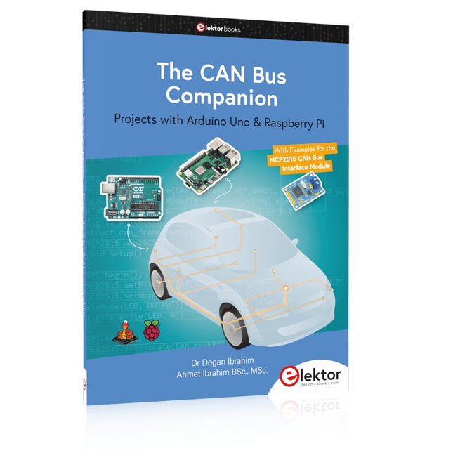
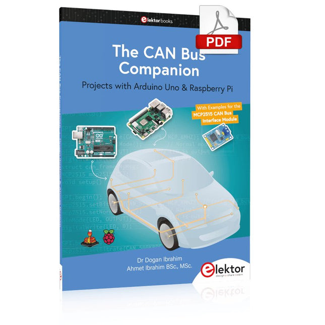
Projects with Arduino Uno & Raspberry Pi with Examples for the MCP2515 CAN Bus Interface Module
This book details the use of the Arduino Uno and the Raspberry Pi 4 in practical CAN bus based projects. Using either the Arduino Uno or the Raspberry Pi with off-the-shelf CAN bus interface modules considerably ease developing, debugging, and testing CAN bus based projects.
This book is written for students, practicing engineers, enthusiasts, and for everyone else wanting to learn more about the CAN bus and its applications. The book assumes that the reader has some knowledge of basic electronics. Knowledge of the C and Python programming languages and programming the Arduino Uno using its IDE and Raspberry Pi will be useful, especially if the reader intends to develop microcontroller-based projects using the CAN bus.
The book should be a useful source of reference material for anyone interested in finding answers to questions such as:
What bus systems are available for the automotive industry?
What are the principles of the CAN bus?
How can I create a physical CAN bus?
What types of frames (or data packets) are available in a CAN bus system?
How can errors be detected in a CAN bus system and how dependable is a CAN bus system?
What types of CAN bus controllers exist?
How do I use the MCP2515 CAN bus controller?
How do I create 2-node Arduino Uno-based CAN bus projects?
How do I create 3-node Arduino Uno-based CAN bus projects?
How do I set the acceptance masks and acceptance filters?
How do I analyze data on the CAN bus?
How do I create 2-node Raspberry Pi-based CAN bus projects?
How do I create 3-node Raspberry Pi-based CAN bus projects?
You can use RF Explorer 3G Combo equally well outdoor and indoor, and you can also connect it to a PC for extra functionality using standard mini-USB 2.0 connector.
This model includes a WSUB1G baseline unit plus an RFEMWSUB3G Expansion Module conveniently assembled and tested. It comes with two SMA connectors and two antennas,a dual band telescopic 144 / 430 MHz antenna for all Sub-GHz frequencies and a whip helical antenna for 2.4 GHz band. Additional, specific band antennas may be needed to cover efficiently some of the frequencies supported.
The combination of these two models offer the wide band coverage of the WSUB3G module, together with the highest sensitivity and quick response of the WSUB1G model for the popular sub-1GHz frequencies.
Features
Pocket size and light weight
Solid aluminum metal case
Includes a transport EVA carry case for RF Explorer
Spectrum Analyzer mode with Peak Max and Hold, Normal, Overwrite and Averaging modes
Lifetime free firmware upgrades available, open to community requested features
High capacity Lipo for 16 hours+ of continuous run, rechargeable by USB
Windows PC client Open Source
Can be extended with internal Expansion Modules for additional band and functionality
Wide band coverage to all popular RF frequencies, starting at 15 MHz and going up to 2.7 GHz. This includes very interesting frequency areas such as 2 m HAM radio, all VHF and UHF, FM radio, GPS, WiFi and WiMax, Bluetooth, etc.
Firmware: RF Explorer 3G Combo is delivered with upgraded firmware v1.09. Note some of the features and operation accuracy will be improved in upcoming free firmware revisions.
Specifications
Battery
Lithium Cells / Batteries contained in equipment UN3481 - PI967
Frequency band
15-2700 MHz
Frequency span
112 KHz - 600 MHz
Graphics LCD
128 x 64 pixels, great visibility outdoors
PC Windows client
supports Windows XP/Vista/Win7 both 32 and 64bits
Backlight
for great indoor visibility
2 standard SMA 50 ohms connector,
one for Sub-GHz wideband Nagoya NA-773 telescopic antenna included and another 2.4 GHz one for 15-2700 MHz band with helical antenna included.
Amplitude resolution
0.5 dBm
Dynamic range
Left SMA port (WSUB1G)
-115 dBm to 0 dBm
Right SMA port (WSUB3G)
-110 dBm to -10 dBm
Absolute Max input power
Left SMA port (WSUB1G)
+5 dBm
Right SMA port (WSUB3G)
+30 dBm
Average noise level (typical)
-110 dBm
Frequency stability and accuracy (typical)
+-10 ppm
Amplitude stability and accuracy (typical)
+-6 dBm
Frequency resolution
1 KHz
Resolution bandwidth (RBW)
automatic 3 KHz to 600 KHz
Weight
185 g
Size
113 x 70 x 25 mm
Included
RF Explorer 3G Combo
Nagoya NA-773 wideband telescopic antenna
2.4 GHz band antenna
EVA Case
Documentation
For more info and to get started with your RF Explorer, visit the start page.
For questions and support, please visit https://support.rf-explorer.com
Features
Internal LNA amplifier and selectable attenuator
Low frequency support from 50KHz covering LF, MF, HF, VHF and UHF up to 960Mhz
New HELP and SET buttons to improve user interface and configuration selection with 2-clicks
Wide band coverage to all popular sub-1Ghz bands, including FM, TV and DTV, ISM, RFID, GSM, etc.
Ideal choice for HAM bands from 160meters to 33cm
Pocket size and light weight
Solid metal case
Spectrum Analyzer mode with Peak Max and Hold, Normal, Overwrite and Averaging modes
High capacity internal Lithium battery for 20hs+ of continuous run, rechargeable by USB
Multi-platform Windows/Linux/MacOS Open Source software and API libraries
Can be extended with internal Expansion Modules for additional band and functionality
Specifications
Frequency band: 0.05 MHz - 960 MHz
Frequency span: 0.1 MHz - 960 MHz
Internal selectable LNA 25 dB gain
Internal selectable Attenuator 30 dB
Graphics LCD 128 x 64 pixels, great visibility outdoors
Support included for Windows, Linux and MacOS X
Backlight for great visibility indoor
Internal Lithium Ion 1800mA/h rechargeable battery
Standard SMA 50 Ω connector
Wideband 144/433MHz dual band telescopic antenna included
UHF 400-900 MHz rubber duck articulated antenna included
Amplitude resolution: 0.5dBm
Dynamic range: -125 dBm to 10 dBm
Absolute Max input power: +30dBm
Average noise level (typical LNA): -125 dBm
Frequency stability and accuracy (typical): +-10 ppm
Amplitude stability and accuracy (typical): +-2d Bm
Frequency resolution: 1kHz
Resolution bandwidth (RBW): automatic 2.6 kHz to 600 kHz
Included
1x RF Explorer WSUB1G+ Spectrum Analyzer
1x Mini USB cable
1x Dual band 144/430MHz Telescopic antenna
1x UHF 400-900Mhz antenna
1x EVA case
Met deze PCIe 3.0 naar dubbele M.2 HAT krijgt de Raspberry Pi 5 toegang tot twee NVMe SSD's, Hailo-8/8L (alleen M.2-sleutel B+M) en Google Coral AI-versnellers met PCIe 3.0-snelheden.
Kenmerken
Dubbele M.2-slots met PCIe 3.0-snelheid: Maakt gebruik van de ASMedia ASM2806 PCIe 3.0-switchchip voor optimale prestaties en omzeilt daarmee de beperkingen van PCIe 2.0.
Stabiele voeding: Extra pogo-pinnen leveren extra vermogen voor een stabiele, snelle verbinding.
Ondersteuning voor meerdere formaten: Compatibel met de standaard M.2-formaten 2230, 2242, 2260 en 2280.
Ontwerp aan de achterkant: Houdt de 40-pins GPIO vrij voor gebruik, waardoor compatibiliteit met andere Raspberry Pi HAT's mogelijk is.
Gebruiksvriendelijk ontwerp: De S-vormige FPC-kabel blokkeert de microSD-kaartsleuf niet.
Open Source-behuizing: De M.2 HAT's van Seeed zijn niet compatibel met de officiële Raspberry Pi-behuizing, maar een aangepaste 3D-printbare behuizing (STP-bestand) kan worden gedownload.
Toepassingen
Ondersteunt tegelijkertijd AI-versnelling en snelle SSD-opslag
Verbindt twee NVMe SSD's voor een grote opslagcapaciteit
Een Raspberry Pi opstarten vanaf de SSD
Specificaties
M.2-slots
2
Max. PCIe-snelheid
PCIe Gen3.0
PCIe-switchchip
ASM2806
Ondersteuning voor M.2-formaat
2280/2260/2242/2230
Max. Voeding
5 V/3 A (max. 3 A: Pogo-pin 2 A + PCIe-connector 1 A)
Kabel
FPC
Montagemethode
Installatie aan de achterkant
Afmetingen
87 x 55 x 10 mm
Inbegrepen
1x Seeed Studio PCIe 3.0 naar Dual M.2 HAT voor Raspberry Pi 5
2x FPC-kabels (50 mm)
1x Schroeven & stud pack
Downloads
Wiki
Projects with Arduino Uno & Raspberry Pi with Examples for the MCP2515 CAN Bus Interface Module
This book details the use of the Arduino Uno and the Raspberry Pi 4 in practical CAN bus based projects. Using either the Arduino Uno or the Raspberry Pi with off-the-shelf CAN bus interface modules considerably ease developing, debugging, and testing CAN bus based projects.
This book is written for students, practicing engineers, enthusiasts, and for everyone else wanting to learn more about the CAN bus and its applications. The book assumes that the reader has some knowledge of basic electronics. Knowledge of the C and Python programming languages and programming the Arduino Uno using its IDE and Raspberry Pi will be useful, especially if the reader intends to develop microcontroller-based projects using the CAN bus.
The book should be a useful source of reference material for anyone interested in finding answers to questions such as:
What bus systems are available for the automotive industry?
What are the principles of the CAN bus?
How can I create a physical CAN bus?
What types of frames (or data packets) are available in a CAN bus system?
How can errors be detected in a CAN bus system and how dependable is a CAN bus system?
What types of CAN bus controllers exist?
How do I use the MCP2515 CAN bus controller?
How do I create 2-node Arduino Uno-based CAN bus projects?
How do I create 3-node Arduino Uno-based CAN bus projects?
How do I set the acceptance masks and acceptance filters?
How do I analyze data on the CAN bus?
How do I create 2-node Raspberry Pi-based CAN bus projects?
How do I create 3-node Raspberry Pi-based CAN bus projects?
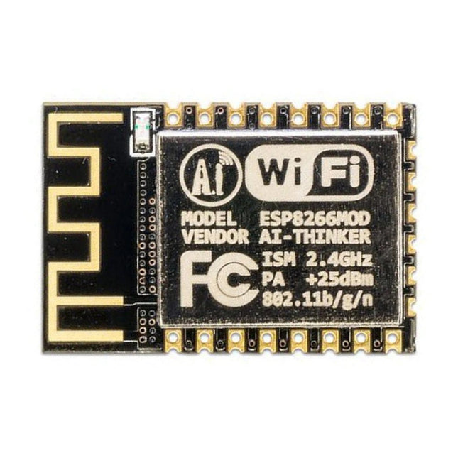
Deze Wi-Fi module is gebaseerd op de populaire ESP8266 chip. De module is FCC en CE gecertificeerd en voldoet aan RoHS. Volledig compatibel met de ESP-12E. 13 GPIO-pinnen, 1 analoge ingang, 4 MB flash-geheugen.
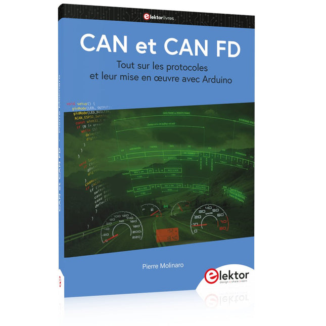
Tout sur les protocoles et leur mise en œuvre avec Arduino
Initialement destiné aux véhicules routiers, le réseau CAN (« Controller Area Network ») et son successeur le réseau CAN FD (« Flexible Data ») ont vu leurs champs d’application s’élargir à de nouveaux domaines. L’industrie propose de nombreux modules microcontrôleurs dotés d’une interface CAN et/ou CAN FD. L’environnement de développement Arduino a démocratisé la programmation de ces modules et il existe des bibliothèques qui implémentent un pilote CAN et/ou un pilote CAN FD.
La première partie dresse un rapide historique des réseaux CAN et CAN FD et expose la problématique des lignes de transmission en abordant succinctement leur théorie et présentant des résultats de simulation Spice.
La deuxième partie est consacrée au réseau CAN, en détaillant successivement la fonction logique du réseau, les transcepteurs, les contrôleurs, la topologie la plus classique (le bus) et d’autres moins courantes, les répéteurs et les passerelles. Les aspects particuliers du protocole, tels que le bit stuffing, l’arbitrage, les trames d’erreur, la détection des erreurs sont exposés. La discussion de la fiabilité du protocole est illustrée par des exemples mettant en évidence ses faiblesses.
La troisième partie présente le protocole CAN FD, ses deux variantes CAN FD ISO et CAN FD non ISO, leurs fiabilités, leurs faiblesses, mises en évidence par des exemples. Différents transcepteurs et contrôleurs CAN FD sont décrits.
La quatrième partie est dédiée aux applications : comment utiliser les services d’un pilote, concevoir une messagerie, utiliser un analyseur logique. Deux exemples d’application terminent cette partie.
Ce livre s’adresse aux amateurs et aux ingénieurs non spécialistes pour comprendre les possibilités qu’offre un réseau CAN et comment on le met en œuvre. Un enseignant trouvera des informations pour approfondir ses connaissances et pour concevoir des travaux pratiques. Une connaissance des microcontrôleurs, de leur programmation, de l’électronique numérique aidera à la lecture des schémas. La connaissance du langage C++ et du langage de simulation électronique Spice facilitera la compréhension des programmes qui sont décrits dans le livre. Tous les codes source sont disponibles sur le dépôt GitHub de l’auteur.
Téléchargements
GitHub
Mastering the I²C Bus takes you on an exploratory journey of the I²C Bus and its applications. Besides the Bus protocol, plenty of attention is given to the practical applications and designing a stable system. The most common I²C compatible chip classes are covered in detail.
Two experimentation boards are available that allow for rapid prototype development. These boards are completed by a USB to I²C probe and a software framework to control I²C devices from your computer. All samples programs can be downloaded from the 'Attachments/Downloads' section on this page.
Projects built on Board 1:
USB to I²C Interface, PCA 9534 Protected Input, PCA 9534 Protected Output, PCA 9553 PWM LED Controller, 24xxx EEPROM Module, LM75 Temperature Sensor, PCA8563 Real-time Clock with Battery Backup, LCD and Keyboard Module, Bus Power Supply.
Projects built on Board 2:
Protected Input, Protected Output, LM75 Temperature Sensor, PCF8574 I/O Board, SAA1064 LED Display, PCA9544 Bus Expander, MCP40D17 Potentiometer, PCF8591 AD/DA, ADC121 A/D Converter, MCP4725 D/A Converter, 24xxx EEPROM Module.
Tout sur les protocoles et leur mise en œuvre avec Arduino
Initialement destiné aux véhicules routiers, le réseau CAN (« Controller Area Network ») et son successeur le réseau CAN FD (« Flexible Data ») ont vu leurs champs d’application s’élargir à de nouveaux domaines. L’industrie propose de nombreux modules microcontrôleurs dotés d’une interface CAN et/ou CAN FD. L’environnement de développement Arduino a démocratisé la programmation de ces modules et il existe des bibliothèques qui implémentent un pilote CAN et/ou un pilote CAN FD.
La première partie dresse un rapide historique des réseaux CAN et CAN FD et expose la problématique des lignes de transmission en abordant succinctement leur théorie et présentant des résultats de simulation Spice.
La deuxième partie est consacrée au réseau CAN, en détaillant successivement la fonction logique du réseau, les transcepteurs, les contrôleurs, la topologie la plus classique (le bus) et d’autres moins courantes, les répéteurs et les passerelles. Les aspects particuliers du protocole, tels que le bit stuffing, l’arbitrage, les trames d’erreur, la détection des erreurs sont exposés. La discussion de la fiabilité du protocole est illustrée par des exemples mettant en évidence ses faiblesses.
La troisième partie présente le protocole CAN FD, ses deux variantes CAN FD ISO et CAN FD non ISO, leurs fiabilités, leurs faiblesses, mises en évidence par des exemples. Différents transcepteurs et contrôleurs CAN FD sont décrits.
La quatrième partie est dédiée aux applications : comment utiliser les services d’un pilote, concevoir une messagerie, utiliser un analyseur logique. Deux exemples d’application terminent cette partie.
Ce livre s’adresse aux amateurs et aux ingénieurs non spécialistes pour comprendre les possibilités qu’offre un réseau CAN et comment on le met en œuvre. Un enseignant trouvera des informations pour approfondir ses connaissances et pour concevoir des travaux pratiques. Une connaissance des microcontrôleurs, de leur programmation, de l’électronique numérique aidera à la lecture des schémas. La connaissance du langage C++ et du langage de simulation électronique Spice facilitera la compréhension des programmes qui sont décrits dans le livre. Tous les codes source sont disponibles sur le dépôt GitHub de l’auteur.
Téléchargements
GitHub