De LoRa-E5 Development Kit is een gemakkelijk te gebruiken compacte ontwikkel-toolset waarmee je de krachtige eigenschappen van de LoRa-E5 STM32WLE5JC kunt ontdekken. Het bestaat uit een LoRa-E5 Dev Board, een antenne (EU868), een USB type C kabel, en een 2-AA 3 V batterijhouder.Het LoRa-E5 Dev Board is uitgerust met de LoRa-E5 STM32WLE5JC module, die de eerste combinatie is van LoRa RF en MCU chip in een kleine enkelvoudige chip, en is FCC en CE gecertificeerd. Hij is voorzien van een ARM Cortex-M4 kern en Semtech SX126X LoRa chip, ondersteunt zowel LoRaWAN als LoRa protocol op de wereldwijde frequentie en (G)FSK, BPSK, (G)MSK, en LoRa modulaties.
Het LoRa-E5 ontwikkelingsboard heeft een zeer groot zendbereik, een extreem laag stroomverbruik en gebruiksvriendelijke interfaces.
Het LoRa-E5 Dev Board heeft een long range zendbereik van LoRa-E5 tot 10 km in een open gebied. Het stroomverbruik van de on-board LoRa-E5 modules in sleep mode is slechts 2.1 µA (WOR mode). Hij is ontworpen volgens industriële normen met een brede werktemperatuur van -40? ~ 85?, hoge gevoeligheid tussen -116.5 dBm ~ -136 dBm, en uitgangsvermogen tot +20.8 dBm bij 3.3 V.
Het LoRa-E5 Dev board heeft ook veel interfaces. Om de volledige functionaliteit van de LoRa-E5 module te kunnen gebruiken heeft het LoRa-E5 Dev Board alle 28 pinnen van LoRa-E5 bedraad en voorziet het van vele interfaces waaronder Grove connectoren, RS-485 terminal, male/female pin headers waarmee je sensoren en modules met verschillende connectoren en gegevensprotocollen kunt aansluiten, zodat je tijd bespaart bij het solderen van draden. Je kunt het board ook gemakkelijk van stroom voorzien door de batterijhouder aan te sluiten met 2-AA batterijen, zodat je het tijdelijk kunt gebruiken zonder externe stroombron. Het is een gebruiksvriendelijke printplaat om gemakkelijk te testen en snel prototypes te maken.
Specificaties
Afmetingen
LoRa-E5 Dev Board: 85.6 x 54 mm
Voedingsspanning
3-5 V (Battery) / 5 V (USB-C)
Uitgangsstroom
EN 3V3 / 5 V
Uitgangsvermogen
Tot +20.8 dBm bij 3.3 V
Frequentie
EU868
Protocol
LoRaWAN
Gevoeligheid
-116.5 dBm ~ -136 dBm
Interfaces
USB Type C / JST2.0 / 3x Grove (2x I²C/1x UART) / RS485 / SMA-K / IPEX
Modulatie
LoRa, (G)FSK, (G)MSK, BPSK
Werktemperatuur
-40? ~ 85?
Stroomverbruik
LoRa-E5 module sleep current slechts 2.1 uA (WOR mode)
Inbegrepen
1x LoRa-E5 Dev Board
1x Antenne (EU868)
1x USB Type C kabel (20 cm)
1x 2-AA 3 V Batterijhouder
This is a high-performance cooling solution designed to effectively dissipate heat and ensure optimal operating temperatures for the Raspberry Pi. It is an essential accessory for users who want to enhance the performance and longevity of their Raspberry Pi device.
The compact design of the Water cooling kit for Raspberry Pi 5 allows it to be seamlessly installed on the top and bottom of the Raspberry Pi 5, ensuring efficient heat transfer and perfectly protecting the bottom of the Raspberry Pi. Its simple installation process eliminates the need for complex wiring or additional tools, making it friendly to both beginners and experienced Raspberry Pi enthusiasts.
With its powerful cooling performance, the water cooling kit for Raspberry Pi 5 for effectively dissipates heat generated by the Raspberry Pi during intensive tasks or prolonged usage. This helps prevent overheating and ensures stable performance. Efficient water-cooled cooling will allow you to connect multiple Raspberry Pi boards to a set of cooling devices. When using Raspberry Pi in a cluster, you can use a set of water-cooled devices to effectively cool multiple Raspberry Pi boards.
Features
Made for Raspberry Pi: Specially designed for Raspberry Pi 5, 1:1 mold opening, covering all heat sources, including CPU, Wi-Fi, power chip, and eMMC.
Cooling Performance: Effectively dissipates the heat generated by the Raspberry Pi, ensuring optimal operating temperatures and preventing overheating.
Easy to Use: The integrated design of the water pump and cooling fan is convenient for users to install.
RGB Color Lighting: RGB-colored lights are installed at the fan and water pump locations.
Included
1x Water cooling kit
1x Water cooling radiator
1x Black heatsink
2x Silicone hose
1x 12 V/2 A power adapter (US)
4x Hexagonal screw M2.5x10
1x L-key hex wrench
You can use RF Explorer 3G Combo equally well outdoor and indoor, and you can also connect it to a PC for extra functionality using standard mini-USB 2.0 connector.
This model includes a WSUB1G baseline unit plus an RFEMWSUB3G Expansion Module conveniently assembled and tested. It comes with two SMA connectors and two antennas,a dual band telescopic 144 / 430 MHz antenna for all Sub-GHz frequencies and a whip helical antenna for 2.4 GHz band. Additional, specific band antennas may be needed to cover efficiently some of the frequencies supported.
The combination of these two models offer the wide band coverage of the WSUB3G module, together with the highest sensitivity and quick response of the WSUB1G model for the popular sub-1GHz frequencies.
Features
Pocket size and light weight
Solid aluminum metal case
Includes a transport EVA carry case for RF Explorer
Spectrum Analyzer mode with Peak Max and Hold, Normal, Overwrite and Averaging modes
Lifetime free firmware upgrades available, open to community requested features
High capacity Lipo for 16 hours+ of continuous run, rechargeable by USB
Windows PC client Open Source
Can be extended with internal Expansion Modules for additional band and functionality
Wide band coverage to all popular RF frequencies, starting at 15 MHz and going up to 2.7 GHz. This includes very interesting frequency areas such as 2 m HAM radio, all VHF and UHF, FM radio, GPS, WiFi and WiMax, Bluetooth, etc.
Firmware: RF Explorer 3G Combo is delivered with upgraded firmware v1.09. Note some of the features and operation accuracy will be improved in upcoming free firmware revisions.
Specifications
Battery
Lithium Cells / Batteries contained in equipment UN3481 - PI967
Frequency band
15-2700 MHz
Frequency span
112 KHz - 600 MHz
Graphics LCD
128 x 64 pixels, great visibility outdoors
PC Windows client
supports Windows XP/Vista/Win7 both 32 and 64bits
Backlight
for great indoor visibility
2 standard SMA 50 ohms connector,
one for Sub-GHz wideband Nagoya NA-773 telescopic antenna included and another 2.4 GHz one for 15-2700 MHz band with helical antenna included.
Amplitude resolution
0.5 dBm
Dynamic range
Left SMA port (WSUB1G)
-115 dBm to 0 dBm
Right SMA port (WSUB3G)
-110 dBm to -10 dBm
Absolute Max input power
Left SMA port (WSUB1G)
+5 dBm
Right SMA port (WSUB3G)
+30 dBm
Average noise level (typical)
-110 dBm
Frequency stability and accuracy (typical)
+-10 ppm
Amplitude stability and accuracy (typical)
+-6 dBm
Frequency resolution
1 KHz
Resolution bandwidth (RBW)
automatic 3 KHz to 600 KHz
Weight
185 g
Size
113 x 70 x 25 mm
Included
RF Explorer 3G Combo
Nagoya NA-773 wideband telescopic antenna
2.4 GHz band antenna
EVA Case
Documentation
For more info and to get started with your RF Explorer, visit the start page.
For questions and support, please visit https://support.rf-explorer.com
Features
Internal LNA amplifier and selectable attenuator
Low frequency support from 50KHz covering LF, MF, HF, VHF and UHF up to 960Mhz
New HELP and SET buttons to improve user interface and configuration selection with 2-clicks
Wide band coverage to all popular sub-1Ghz bands, including FM, TV and DTV, ISM, RFID, GSM, etc.
Ideal choice for HAM bands from 160meters to 33cm
Pocket size and light weight
Solid metal case
Spectrum Analyzer mode with Peak Max and Hold, Normal, Overwrite and Averaging modes
High capacity internal Lithium battery for 20hs+ of continuous run, rechargeable by USB
Multi-platform Windows/Linux/MacOS Open Source software and API libraries
Can be extended with internal Expansion Modules for additional band and functionality
Specifications
Frequency band: 0.05 MHz - 960 MHz
Frequency span: 0.1 MHz - 960 MHz
Internal selectable LNA 25 dB gain
Internal selectable Attenuator 30 dB
Graphics LCD 128 x 64 pixels, great visibility outdoors
Support included for Windows, Linux and MacOS X
Backlight for great visibility indoor
Internal Lithium Ion 1800mA/h rechargeable battery
Standard SMA 50 Ω connector
Wideband 144/433MHz dual band telescopic antenna included
UHF 400-900 MHz rubber duck articulated antenna included
Amplitude resolution: 0.5dBm
Dynamic range: -125 dBm to 10 dBm
Absolute Max input power: +30dBm
Average noise level (typical LNA): -125 dBm
Frequency stability and accuracy (typical): +-10 ppm
Amplitude stability and accuracy (typical): +-2d Bm
Frequency resolution: 1kHz
Resolution bandwidth (RBW): automatic 2.6 kHz to 600 kHz
Included
1x RF Explorer WSUB1G+ Spectrum Analyzer
1x Mini USB cable
1x Dual band 144/430MHz Telescopic antenna
1x UHF 400-900Mhz antenna
1x EVA case
Maker Line is een lijnsensor met 5 x IR sensoren array die in staat is om lijnen te volgen van 13 mm tot 30 mm breedte.
De sensor calibratie is ook vereenvoudigd. Het is niet nodig om de potentiometer voor elke IR sensor aan te passen. U hoeft alleen maar de calibrate knop gedurende 2 seconden in te drukken om de calibratie modus te openen. Daarna moet u de sensoren over de lijn laten vegen, nogmaals op de knop drukken en u bent klaar om te gaan.
De kalibratiegegevens worden opgeslagen in EEPROM en deze blijven intact, zelfs als de sensor is uitgeschakeld. Kalibratie hoeft dus maar één keer te worden uitgevoerd, tenzij de sensorhoogte, lijnkleur of achtergrondkleur is veranderd.
Maker Line ondersteunt ook dubbele uitgangen: 5 x digitale uitgangen voor de status van elke sensor onafhankelijk, wat vergelijkbaar is met conventionele IR-sensor, maar u krijgt het voordeel van eenvoudige kalibratie, en ook een analoge uitgang, waar de spanning de lijnpositie vertegenwoordigt. De analoge uitgang biedt ook een hogere resolutie in vergelijking met afzonderlijke digitale uitgangen. Dit is vooral nuttig wanneer een hoge nauwkeurigheid vereist is bij het bouwen van een lijnvolgende robot met PID regeling.
Kenmerken
Bedrijfsspanning: DC 3,3 V en 5 V compatibel (met omgekeerde polariteitsbeveiliging)
Aanbevolen lijndikte: 13 mm tot 30 mm
Selecteerbare lijnkleur (licht of donker)
Sensor afstand (hoogte): 4 mm tot 40 mm (Vcc = 5 V, zwarte lijn op wit oppervlak)
Sensor Vernieuwingsfrequentie: 200 Hz
Eenvoudig kalibratieproces
Dubbele uitgangstypen: 5 x digitale uitgangen vertegenwoordigen elke IR-sensor staat, 1 x analoge uitgang vertegenwoordigt lijn positie.
Ondersteunt een breed scala aan controllers, zoals Arduino, Raspberry Pi etc.
Downloads
Datasheet
Tutorial: Een goedkope lijnvolgende robot bouwen
Principles, Systems, and Electronics
This handbook provides a detailed study of the sensors and actuators at the heart of modern vehicle electronics. It begins with basic electrical and electronic concepts, introducing the principles and terminology essential for understanding automotive systems.
The book explores sensors and actuators on a system-by-system basis, including:
Fundamentals of electrical engineering, electromagnetic phenomena, and motor principles
Passive and active electronic components, integrated circuits, protection devices, and automotive-grade electronics
Sensor characteristics, signal conditioning, ADCs, PWM and frequency outputs, and interface adaptation
Automotive communication links and protocols, including LIN and SENT
Engine sensors: air mass, pressure, temperature, speed, position, exhaust and emissions-related sensors
Transmission sensors for manual and automatic systems
Steering and suspension sensors for conventional and active systems
Vehicle body and electrical system sensors for comfort, climate, access, and monitoring functions
Engine actuators such as throttle bodies, injectors, turbo actuators, EGR systems, ignition components, and pumps
Transmission, brake, steering, suspension, and body actuators
Identification and coding of electronic components and packages commonly used in automotive applications
The structure and operating principles of each component are explained, with relevant electronic circuitry illustrated. Its system-oriented organization and practical focus make it a valuable reference for understanding, testing, and troubleshooting automotive electronic systems.
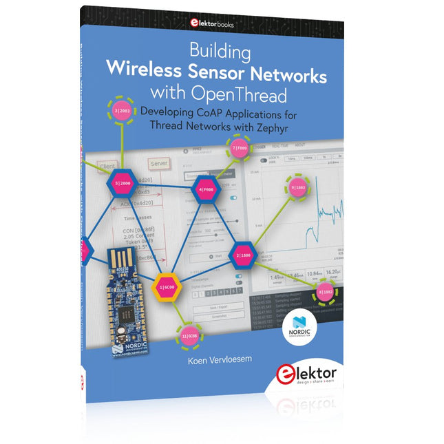
Developing CoAP applications for Thread networks with Zephyr
This book will guide you through the operation of Thread, the setup of a Thread network, and the creation of your own Zephyr-based OpenThread applications to use it. You’ll acquire knowledge on:
The capture of network packets on Thread networks using Wireshark and the nRF Sniffer for 802.15.4.
Network simulation with the OpenThread Network Simulator.
Connecting a Thread network to a non-Thread network using a Thread Border Router.
The basics of Thread networking, including device roles and types, as well as the diverse types of unicast and multicast IPv6 addresses used in a Thread network.
The mechanisms behind network discovery, DNS queries, NAT64, and multicast addresses.
The process of joining a Thread network using network commissioning.
CoAP servers and clients and their OpenThread API.
Service registration and discovery.
Securing CoAP messages with DTLS, using a pre-shared key or X.509 certificates.
Investigating and optimizing a Thread device’s power consumption.
Once you‘ve set up a Thread network with some devices and tried connecting and disconnecting them, you’ll have gained a good insight into the functionality of a Thread network, including its self-healing capabilities. After you’ve experimented with all code examples in this book, you’ll also have gained useful programming experience using the OpenThread API and CoAP.
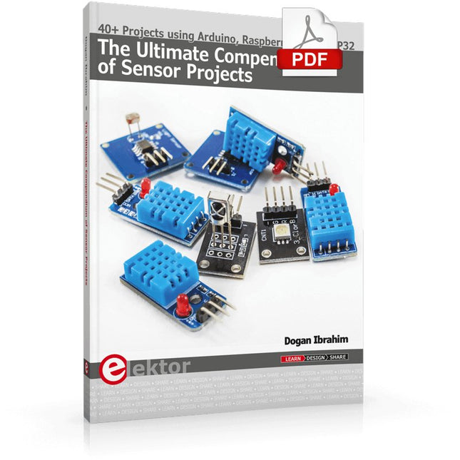
40+ Projects using Arduino, Raspberry Pi and ESP32
This book is about developing projects using the sensor-modules with Arduino Uno, Raspberry Pi and ESP32 microcontroller development systems. More than 40 different sensors types are used in various projects in the book. The book explains in simple terms and with tested and fully working example projects, how to use the sensors in your project. The projects provided in the book include the following:
Changing LED brightness
RGB LEDs
Creating rainbow colours
Magic wand
Silent door alarm
Dark sensor with relay
Secret key
Magic light cup
Decoding commercial IR handsets
Controlling TV channels with IT sensors
Target shooting detector
Shock time duration measurement
Ultrasonic reverse parking
Toggle lights by clapping hands
Playing melody
Measuring magnetic field strength
Joystick musical instrument
Line tracking
Displaying temperature
Temperature ON/OFF control
Mobile phone-based Wi-Fi projects
Mobile phone-based Bluetooth projects
Sending data to the Cloud
The projects have been organized with increasing levels of difficulty. Readers are encouraged to tackle the projects in the order given. A specially prepared sensor kit is available from Elektor. With the help of this hardware, it should be easy and fun to build the projects in this book.
Principles, Systems, and Electronics
This handbook provides a detailed study of the sensors and actuators at the heart of modern vehicle electronics. It begins with basic electrical and electronic concepts, introducing the principles and terminology essential for understanding automotive systems.
The book explores sensors and actuators on a system-by-system basis, including:
Fundamentals of electrical engineering, electromagnetic phenomena, and motor principles
Passive and active electronic components, integrated circuits, protection devices, and automotive-grade electronics
Sensor characteristics, signal conditioning, ADCs, PWM and frequency outputs, and interface adaptation
Automotive communication links and protocols, including LIN and SENT
Engine sensors: air mass, pressure, temperature, speed, position, exhaust and emissions-related sensors
Transmission sensors for manual and automatic systems
Steering and suspension sensors for conventional and active systems
Vehicle body and electrical system sensors for comfort, climate, access, and monitoring functions
Engine actuators such as throttle bodies, injectors, turbo actuators, EGR systems, ignition components, and pumps
Transmission, brake, steering, suspension, and body actuators
Identification and coding of electronic components and packages commonly used in automotive applications
The structure and operating principles of each component are explained, with relevant electronic circuitry illustrated. Its system-oriented organization and practical focus make it a valuable reference for understanding, testing, and troubleshooting automotive electronic systems.
Developing CoAP applications for Thread networks with Zephyr
This book will guide you through the operation of Thread, the setup of a Thread network, and the creation of your own Zephyr-based OpenThread applications to use it. You’ll acquire knowledge on:
The capture of network packets on Thread networks using Wireshark and the nRF Sniffer for 802.15.4.
Network simulation with the OpenThread Network Simulator.
Connecting a Thread network to a non-Thread network using a Thread Border Router.
The basics of Thread networking, including device roles and types, as well as the diverse types of unicast and multicast IPv6 addresses used in a Thread network.
The mechanisms behind network discovery, DNS queries, NAT64, and multicast addresses.
The process of joining a Thread network using network commissioning.
CoAP servers and clients and their OpenThread API.
Service registration and discovery.
Securing CoAP messages with DTLS, using a pre-shared key or X.509 certificates.
Investigating and optimizing a Thread device’s power consumption.
Once you‘ve set up a Thread network with some devices and tried connecting and disconnecting them, you’ll have gained a good insight into the functionality of a Thread network, including its self-healing capabilities. After you’ve experimented with all code examples in this book, you’ll also have gained useful programming experience using the OpenThread API and CoAP.
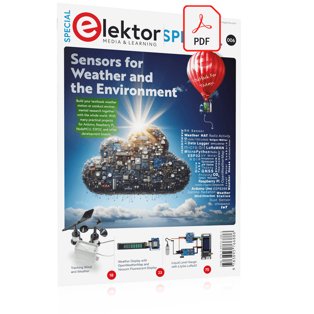
Build your textbook weather station or conduct environmental research together with the whole world. With many practical projects for Arduino, Raspberry Pi, NodeMCU, ESP32, and other development boards.
Weather stations have enjoyed great popularity for decades. Every current and even every long discontinued electronics magazine has regularly featured articles on building your own weather station. Over the years, they have become increasingly sophisticated and can now be fully integrated into an automated home — although this often requires loyalty to an (expensive) brand manufacturer across all components.
With your own weather and environmental data, you can keep up and measure things that no commercial station can. It’s also fun: expand your knowledge of electronics, current microcontroller development boards and programming languages in a fun and meaningful way. For less than 10 euros you can get started and record your first environmental data — with time and growing interest, you will continue to expand your system.
In this Edition
Which Microcontroller Fits My Project?
The Right Development Environment
Tracking Wind and Weather
Weather Display with OpenWeatherMap and Vacuum Fluorescent Display
Volatile Organic Compounds in the Air We Breathe
Working with MQ Sensors: Measuring Carbon Monoxide — Odorless but Toxic
CO2 Traffic Light with ThingSpeak IoT Connection
An Automatic Plant Watering System
Good Indoor Climate: Temperature and Humidity are Important criteria
Classy Thermometer with Vintage Tube Technology
Nostalgic Weather House for the Whole Family
Measuring Air Pressure and Temperature Accurately
Sunburn Warning Device
DIY Sensor for Sunshine Duration
Simple Smartphone Says: Fog or Clear View?
Identifying Earthquakes
Liquid Level Measurement for Vessels and Reservoirs
Water pH Value Measurement
Detecting Radioactive Radiation
GPS: Sensor Location Service Across the Globe
Saving and Timestamping Log Files on SD Cards
LoRaWAN, The Things Network, and ThingSpeak
Operating a LoRaWAN Gateway for TTN
Defying "Wind and Weather"
Mega Display with Weather Forecasz