The Red Pitaya (STEMlab) is a credit card-sized, open-source test and measurement board that can be used to replace most measurement instruments used in electronics laboratories. With a single click, the board can transform into a web-based oscilloscope, spectrum analyser, signal generator, LCR meter, Bode plotter, and microcontroller.
The Red Pitaya (STEMlab) can replace the many pieces of expensive measurement equipment found at professional research organisations and teaching laboratories. The device, that based on Linux, includes an FPGA, digital signal processing (DSP), dual core ARM Cortex processor, signal acquisition and generation circuitry, micro USB socket, microSD card slot, RJ45 socket for Ethernet connection, and USB socket – all powered from an external mains adaptor.
This book is an introduction to electronics. It aims to teach the principles and applications of basic electronics by carrying out real experiments using the Red Pitaya (STEMlab). The book includes many chapters on basic electronics and teaches the theory and use of electronic components including resistors, capacitors, inductors, diodes, transistors, and operational amplifiers in electronic circuits. Many fun and interesting Red Pitaya (STEMlab) experiments are included in the book. The book also makes an introduction to visual programming environment.
The book is written for college level and first year university students studying electrical or electronic engineering.
De ESP32-S3-BOX-3 is gebaseerd op Espressif's ESP32-S3 Wi-Fi + Bluetooth 5 (LE) SoC, met AI versnellingsmogelijkheden. Als toevoeging op de 512 KB SRAM van de ESP32-S3 wordt de ESP32-S3-BOX-3 geleverd met 16 MB Quad flash en 16 MB Octaal PSRAM.
De ESP32-S3-BOX-3 draait op Espressif's eigen spraakherkenningsframework, ESP-SR, dat gebruikers een offline AI spraakassistent biedt. Hij beschikt over far-field voice interaction, continue herkenning, wake-up interruption, en de mogelijkheid om meer dan 200 aanpasbare opdrachtwoorden te herkennen. De BOX-3 kan ook worden omgevormd tot een online AI chatbot met behulp van geavanceerde AIGC ontwikkelingsplatforms, zoals OpenAI.
Aangestuurd door de krachtige ESP32-S3 SoC biedt de BOX-3 ontwikkelaars een kant-en-klare oplossing voor het maken van Edge AI en HMI toepassingen. De geavanceerde functies en mogelijkheden van de BOX-3 maken hem tot een ideale keuze voor diegenen in de IIoT industrie die Industrie 4.0 willen omarmen en traditionele fabrieksbesturingssystemen willen transformeren.
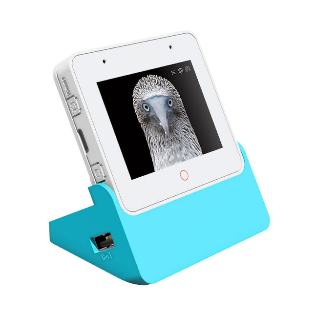
De ESP32-S3-BOX-3 is de hoofd unit die wordt aangestuurd door de ESP32-S3-WROOM-1 module, die 2,4 GHz Wi-Fi + Bluetooth 5 (LE) biedt, evenals AI versnellingsmogelijkheden. In aanvulling op de 512 KB SRAM van de ESP32-S3 SoC wordt de module geleverd met een extra 16 MB Quad flash en 16 MB Octal PSRAM. Het board is uitgerust met een 2,4-inch 320 x 240 SPI-touchscreen (de 'rode cirkel' ondersteunt aanraking), twee digitale microfoons, een luidspreker, een 3-assige gyroscoop, een 3-assige accelerometer, een Type-C poort voor voeding en downloaden/debuggen, een high-density PCIe-connector die uitbreiding van de hardware mogelijk maakt, en ook drie functionele knoppen.
Kenmerken
ESP32-S3
WiFi + Bluetooth 5 (LE)
512 KB SRAM
ESP32-S3-WROOM-1
16 MB Quad flash
16 MB Octaal PSRAM
Inbegrepen
ESP32-S3-BOX-3 Eenheid
ESP32-S3-BOX-3 Sensor
ESP32-S3-BOX-3 Dock
ESP32-S3-BOX-3 Beugel
ESP32-S3-BOX-3 Bread
RGB LED-module en Dupont draden
USB-C kabel
Downloads
GitHub
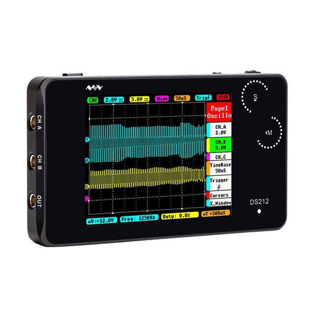
An 8-in-1 test & measurement instrument for the electronics workbench
A well-equipped electronics lab is crammed with power supplies, measuring devices, test equipment and signal generators. Wouldn‘t it be better to have one compact device for almost all tasks? Based on the Arduino, a PC interface is to be developed that’s as versatile as possible for measurement and control. It simply hangs on a USB cable and – depending on the software – forms the measuring head of a digital voltmeter or PC oscilloscope, a signal generator, an adjustable voltage source, a frequency counter, an ohmmeter, a capacitance meter, a characteristic curve recorder, and much more.
The circuits and methods collected here are not only relevant for exactly these tasks in the "MSR" electronics lab, but many details can also be used within completely different contexts.
Features
Synchronous mode: Auto, Normal, Single, None, Scan
Rising/Falling edge trigger
Modes of vertical precise, horizontal precise measurement and triggering threshold
Auto Measurement: frequency, cycle time, duty cycle, DC RMS voltage/Vpp /Vmax/Vmin/Vavg
Inbuilt signal generator/10 Hz-1 MHz square wave (duty adjustable) or 10 Hz-20 KHz
Sine/Square/Triangle/Sawtooth wave
Specifications
Analog bandwidth
1 MHz
Max sample rate
10 Msa/s
Max sample memory depth
8K
Analog input impedance
1 M?
Max input voltage
±40 V (X1)
Coupling
AC/DC
Vertical sensitivity
20 mv/Div~10 V/Div (1-2-5)
Horizontal sensitivity
1 uS/Div~2 S/Div (1-2-5)
Storage
Built-in 8 MB U disk storage for waveform data and images
Power supply
Internal 550 mAh Lithium battery, recharging through Micro USB port
Display
2.8' Full Color TFT LCD (320x240 pixels)
Dimensions
100 x 56.5 x 10.7 mm
Downloads
User Manual
Source Code
App
An 8-in-1 test & measurement instrument for the electronics workbench
A well-equipped electronics lab is crammed with power supplies, measuring devices, test equipment and signal generators. Wouldn‘t it be better to have one compact device for almost all tasks? Based on the Arduino, a PC interface is to be developed that’s as versatile as possible for measurement and control. It simply hangs on a USB cable and – depending on the software – forms the measuring head of a digital voltmeter or PC oscilloscope, a signal generator, an adjustable voltage source, a frequency counter, an ohmmeter, a capacitance meter, a characteristic curve recorder, and much more.
The circuits and methods collected here are not only relevant for exactly these tasks in the "MSR" electronics lab, but many details can also be used within completely different contexts.
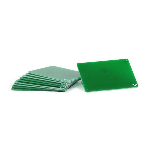
If you are going to be drilling, we recommend drilling on FR1 substrates. Unlike FR4, FR1 dust does not contain fiber glass. It is also a softer material, which means a less wear and tear on the drill bits. Download the template and incorporate them into your design here. 10 substrates included.
This book is intended as a highly-practical guide for Hobbyists, Engineers and Scientists wishing to build measurement and control systems to be controlled by a local or remote Personal Computer running the Linux operating system. Both hardware and software aspects of designing typical embedded systems are covered in detail with schematics, code listings and full descriptions. Numerous examples have been designed to show clearly how straightforward it can be to create the interfaces between digital and analog electronics, with programming techniques for creating control software for both local and remote systems. Hardware developers will appreciate the variety of circuits, including a novel, low cost modulated wireless link and will discover how using Matlab® overcomes the need for specialist programming skills.
Software developers will appreciate how a better understanding of circuits plus the freedom offered by Linux to directly control at the register level enables them to optimize related programs. There is no need to buy special equipment or expensive software tools in order to create embedded projects covered in this book. You can build such quality systems quickly using popular low-cost electronic components and free distributed or low-cost software tools. Some knowledge of basic electronics plus the very basics of C programming only is required.
Many projects in this book are developed using Matlab® being a very popular worldwide computational tool for research in engineering and science. The book provides a detailed description of how to combine the power of Matlab® with practical electronics.
With an emphasis on learning by doing, readers are encouraged by examples to program with ease; the book provides clear guidelines as to the appropriate programming techniques “on the fly”. Complete and well-documented source code is provided for all projects.
If you want to learn how to quickly build Linux-based applications able to collect, process and display data on a PC from various analog and digital sensors, how to control circuitry attached to a computer, then even how to pass data via a network or control your embedded system wirelessly and more – then this is the book for you!
Features of this Book
Use the power, flexibility and control offered only by a Linux operating system on a PC.
Use a free, distributed downloadable GNU C compiler Use (optional) a low-cost Student Version of Matlab®.
Use low-cost electronic sub-assemblies for projects.
Improve your skills in electronics, programming, networking and wireless design.
A full chapter is dedicated to controlling your sound card for audio input and output purposes.
Program sound using OSS and ALSA.
Learn how to combine electronic circuits, software, networks and wireless technologies in the complete embedded system.
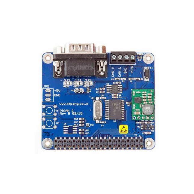
This PiCAN 2 board provides CAN-Bus capability for the Raspberry Pi 2/3. It uses the Microchip MCP2515 CAN controller with MCP2551 CAN transceiver. Connection are made via DB9 or 3-way screw terminal. This board includes a switch mode power suppler that powers the Raspberry Pi is well.
Easy to install SocketCAN driver. Programming can be done in C or Python.
Not suitable for Raspberry Pi 4, please use PiCAN 3 instead.
Kenmerken
CAN v2.0B at 1 Mb/s
High speed SPI Interface (10 MHz)
Standard and extended data and remote frames
CAN connection via standard 9-way sub-D connector or screw terminal
Compatible with OBDII cable
Solder bridge to set different configuration for DB9 connector
120Ω terminator ready
Serial LCD ready
LED indicator
Foot print for two mini push buttons
Four fixing holes, comply with Pi Hat standard
SocketCAN driver, appears as can0 to application
Interrupt RX on GPIO25
5 V/1 A SMPS to power Raspberry Pi and accessories from DB9 or screw terminal
Reverse polarity protection
High efficiency switch mode design
6-20 V input range
Optional fixing screws – select at bottom of this webpage
Downloads
User guide
Schematic Rev B
Writing your own program in Python
Python3 examples in Github
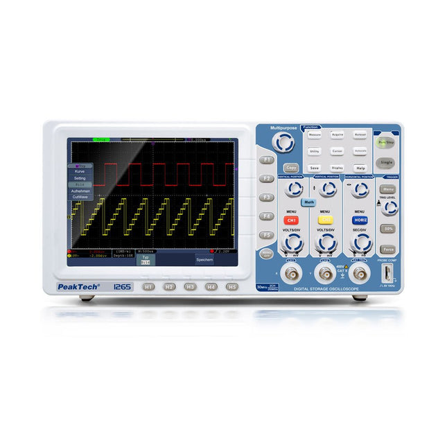
De PeakTech 1265 is een betaalbare 30 MHz 2-kanaals digitale geheugen-oscilloscoop met een TFT-kleurendisplay met hoge resolutie, en uitgebreide extra functies. Hij heeft een sampling rate van maximaal 250 MS/s en imponeert door zijn hoge kwaliteit en eenvoudige bediening met de beste prijs/prestatieverhouding. Om snel een inkomende golfvorm weer te geven drukt u gewoon op de Autoset-toets, waarna de oscilloscoop zelf naar de best mogelijke weergave zoekt. Danwel kan met Autoscale de schaal van de tijdbasis op een gebruiksvriendelijke manier worden aangepast. Deze oscilloscoop heeft een VGA-uitgang voor het weergeven van het oscilloscoopbeeld op een externe monitor of projector. Kenmerken 2-kanaals oscilloscoop met 30 MHz analoge bandbreedte bij een sampling rate van maximaal 250 MS/s 8 inch (20 cm) TFT-kleurendisplay met 800 x 600 pixels LAN, USB-host, USB-apparaat & VGA-interface Autoset functie voor gebruiksvriendelijke bediening Opname mogelijkheid van maximaal 10.000 punten Automatische meetmodi, XY-modus en FFT-functie Specificaties Bandbreedte 30 MHz Kanalen 2 Schermgrootte (TFT) 8' (20 cm) Resolutie 800 x 600 pixel Display type TFT-kleur Sampling 1 kanaal 250 MS/s Sampling 2 kanalen 125 MS/s Hor. schaal max. 100 s/div Hor. schaal min. 5 ns/div Geheugen 10.000 Punten Stijgtijd < 14 NS Vert. resolutie 8 bits Vert. schaal max. 10 V/div Vert. schaal min. 2 mV/div Interfaces 1x USB, 1x LAN, 1x VGA Netspanning 110/240 V AC; 50/60 Hz Inbegrepen PeakTech 1265 Oscilloscoop USB-kabel Software CD voor Windows Netsnoer 2 Probes BNC-kabel Draagtas Handleiding Downloads Software Datasheet_DE-EN Datasheet_FR Datasheet_IT Datasheet_ES
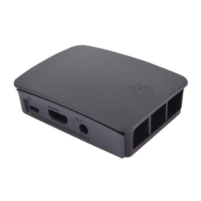
High-quality ABS construction Removable side panels and lid for easy access to GPIO, camera and display connectors Light pipes for power and activity LEDs Extraordinarily handsome Colour: black/grey
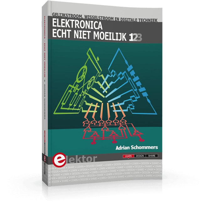
Elektronica moeilijk? De titel van dit boek geeft het antwoord!
In deze 3-in-1-band wordt de elektronica vanuit de praktijk benaderd. Dat wil zeggen veel praktijk in de vorm van experimenten en een minimum aan theorie. Zo raakt u stap voor stap vertrouwd met de behandelde onderwerpen. Daarbij ontstaan gaandeweg ook een flink aantal praktisch bruikbare schakelingen. Het gaat bij de elektronicahobby tenslotte om het bouwen of uitdenken van allerlei praktische of leuke schakelingen.
Aan het eind van elk deel is een aanhangsel opgenomen met aanvullende informatie en de gegevens van een groot aantal elektronische componenten, zodat na dit boek ook eigen ideeën en experimenten kunnen worden aangepakt.
In deze 3-in-1-band zijn de eerste drie delen uit de serie “Elektronica echt niet moeilijk” samengevoegd:
Deel 1: experimenten met gelijkstroom
Deel 2: experimenten met wisselstroom
Deel 3: experimenten met digitale techniek
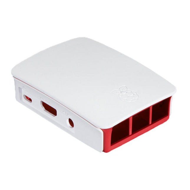
High-quality ABS construction Removable side panels and lid for easy access to GPIO, camera and display connectors Light pipes for power and activity LEDs Extraordinarily handsome Colour: white/red