Zoekresultaten voor "pages"
-
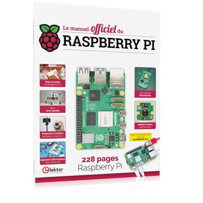
Elektor Publishing Le manuel officiel du Raspberry Pi
Réalisés par les créateurs du MagPi, le magazine officiel de Raspberry Pi Démarrez avec le Raspberry Pi 5, le dernier-né et le plus performant de la famille des nano-ordinateurs Raspberry Pi. Apprenez à coder et à réaliser des projets avec cet ordinateur étonnant. Dans ce manuel dédié au Raspberry Pi 5, nous vous proposons aussi de nombreuses idées de projets également réalisables avec le Raspberry Pi 4, le Raspberry Pi Zero 2 W et le Raspberry Pi Pico W. Avec des tutoriels, des projets pratiques, des essais techniques, des guides et bien plus encore, il s’agit de la ressource ultime pour le Raspberry Pi ! 228 pages sur le Raspberry Pi Tout ce que vous devez savoir sur le Raspberry Pi 5 Prise en main de tous les Raspberry Pi Amusez-vous et apprenez l’électronique avec le Pico W Des projets inspirants pour vous donner des idées de réalisations Apprenez μPython en construisant une mini-console Démarrez avec le module caméra Raspberry Pi Intelligence artificielle, codage de son propre agent ChatGP
€ 34,95
Leden € 31,46
-
Elektor Classics The Complete Linear Audio Library (USB-stick)
Jan Didden schiep Linear Audio in 2010 en publiceerde 14 delen tussen 2010 en 2017. Elk deel van 200 bladzijden bevat gemiddeld 10 artikelen van deskundige auteurs op het gebied van audio, akoestiek, en instrumentatie. Of je nu geïnteresseerd bent in buizenversterkers, solid-state apparatuur, luidsprekerontwerp, condensator- en weerstandsvervorming of vervormingsmeting, je vindt er zeker nuttige adviezen en interessante discussies. Van beginner tot gevorderd niveau, voor de audio professional of de serieuze hobbyist, deze ExpertCollection zal je kennis vergroten en nieuwe perspectieven bieden op veel voorkomende problemen. Bonusmateriaal bij deze collectie is een 5-delige YouTube serie over negatieve feedback toegepast op audio van de bekende auteur Jan Didden, en nog negen andere baanbrekende audio artikelen en presentaties. Als je serieus geïnteresseerd bent in audio, akoestiek, en instrumentatie, mag je dit niet missen! Het gepubliceerde materiaal is geïndexeerd en volledig doorzoekbaar en zal een bijna onbeperkte bron zijn voor vele jaren. Je kunt over de auteurs van Linear Audio lezen, en de inhoudsopgave van elk deel, zie linearaudio.net.
€ 149,95€ 59,98
Leden identiek
-
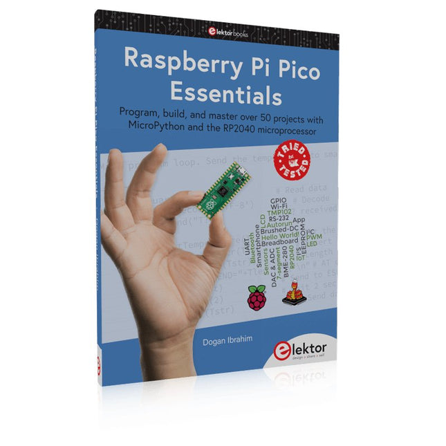
Elektor Publishing Raspberry Pi Pico Essentials
Program, build, and master over 50 projects with MicroPython and the RP2040 microprocessor The Raspberry Pi Pico is a high-performance microcontroller module designed especially for physical computing. Microcontrollers differ from single-board computers, like the Raspberry Pi 4, in not having an operating system. The Raspberry Pi Pico can be programmed to run a single task very efficiently within real-time control and monitoring applications requiring speed. The ‘Pico’ as we call it, is based on the fast, efficient, and low-cost dual-core ARM Cortex-M0+ RP2040 microcontroller chip running at up to 133 MHz and sporting 264 KB of SRAM, and 2 MB of Flash memory. Besides its large memory, the Pico has even more attractive features including a vast number of GPIO pins, and popular interface modules like ADC, SPI, I²C, UART, and PWM. To cap it all, the chip offers fast and accurate timing modules, a hardware debug interface, and an internal temperature sensor. The Raspberry Pi Pico is easily programmed using popular high-level languages such as MicroPython and or C/C++. This book is an introduction to using the Raspberry Pi Pico microcontroller in conjunction with the MicroPython programming language. The Thonny development environment (IDE) is used in all the projects described. There are over 50 working and tested projects in the book, covering the following topics: Installing the MicroPython on Raspberry Pi Pico using a Raspberry Pi or a PC Timer interrupts and external interrupts Analogue-to-digital converter (ADC) projects Using the internal temperature sensor and external temperature sensor chips Datalogging projects PWM, UART, I²C, and SPI projects Using Wi-Fi and apps to communicate with smartphones Using Bluetooth and apps to communicate with smartphones Digital-to-analogue converter (DAC) projects All projects given in the book have been fully tested and are working. Only basic programming and electronics experience is required to follow the projects. Brief descriptions, block diagrams, detailed circuit diagrams, and full MicroPython program listings are given for all projects described. Readers can find the program listings on the Elektor web page created to support the book.
€ 39,95
Leden € 35,96
-

Elektor Publishing Vintage Radio Equipment
Resonances From Aether Days A Pictorial and Technical Analysis from WWII to the Internet Age From the birth of radio to the late 1980s, much of real life unfolded through shortwave communication. World War II demonstrated—beyond a shadow of a doubt—that effective communications equipment was a vital prerequisite for military success. In the postwar years, shortwave became the backbone on which many of the world's most critical services depended every day. All the radio equipment—through whose cathodes, grids, plates, and transistors so much of human history has flowed—is an exceptional subject of study and enjoyment for those of us who are passionate about vintage electronics. In this book, which begins in the aftermath of World War II, you’ll find a rich collection of information: descriptions, tips, technical notes, photos, and schematics that will be valuable for anyone interested in restoring—or simply learning about—these extraordinary witnesses to one of the most remarkable eras in technological history. My hope is that these pages will help preserve this vast treasure of knowledge, innovation, and history—a heritage that far transcends the purely technical.
€ 79,95
Leden € 71,96
-

Elektor Publishing Renewable Energy at Home
A Hands-on Guide to Crafting Your Own Power Plant The book you are about to read provides a step-by-step guide for building a renewable energy power plant at home. Our goal was to make the book as practical as possible. The material is intended for immediate application with a small amount of theory. Yet, the theory is important as a foundation that saves time and effort by disabusing the readers of potential misconceptions. Specifically, upon having a firm understanding of photovoltaic physics, you will not be inclined to fruitlessly search for 90% efficient solar panels! We want our readers to be the “doers”. If the book gets covered in grime and some pages become torn while you are building your power plant – this is the best compliment to us. The book covers solar and wind energy. Also, a curious power source based on manure is discussed as well, giving the doers an opportunity to further develop the manure fuel cell. It is important to note that there are many companies offering installation of complete solar solutions. Upon installing the panels, the system is not owned by the customer. Therefore, there is no freedom for experimentation and optimization. Also, none can beat the cost of a DIY solution as well as the ultimate satisfaction. All that is written here is a result of us building a renewable energy solution in Southern California. As the book was completed, the energy began flowing!
€ 29,95
Leden € 26,96
-
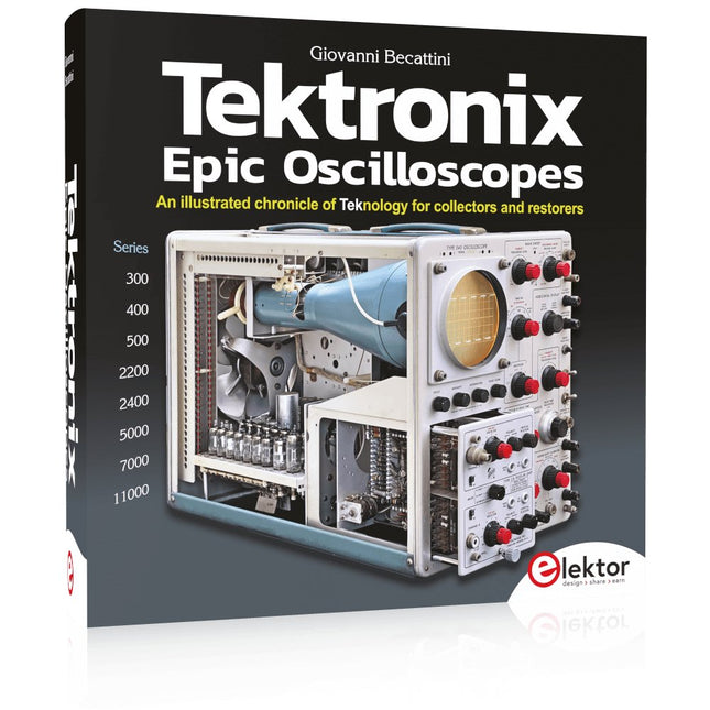
Elektor Publishing Tektronix Epic Oscilloscopes
Een geïllustreerde kroniek van technologienologie voor verzamelaars en restaurateurs Oscilloscopen hebben een belangrijke bijdrage geleverd aan de vooruitgang van de menselijke kennis, niet alleen op het gebied van de elektronica, maar in alle wetenschappen, waar een fysieke grootheid kan worden omgezet in een tijdgerelateerd elektrisch signaal. Dit boek beschrijft de geschiedenis van een cruciaal instrument via vele Tektronix producten. Dit is het bedrijf dat de meeste functies heeft uitgevonden en gepatenteerd die tegenwoordig in alle oscilloscopen te vinden zijn. Tek is en blijft synoniem met de oscilloscoop. In bijna 600 pagina's, met honderden prachtige foto's, diagrammen, anekdotes en technische gegevens, reis je door de geschiedenis van Tektronix in een prachtige verzameleditie met een technisch perspectief. De auteur is niet bang om zijn handen vuil te maken door zijn eigen Tek-apparatuur te restaureren. De reis begint begin jaren vijftig. Het eindigt in de jaren '90, na het verkennen van de ins en outs van de meest interessante modellen in de 300, 400, 500, 5000, 7000 en 11000-serie, van buizen tot geavanceerde hybride technologieën. Downloads NIEUW: Gratis Supplement (136 pagina's, 401 MB)
€ 79,95
Leden € 71,96
-
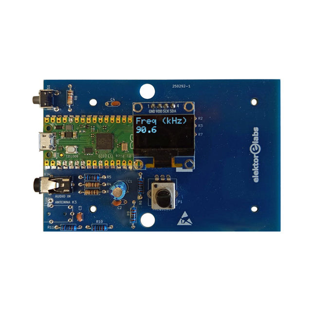
Elektor Labs Elektor AM-zender Kit
Bouw je eigen vintage radiozender De Elektor AM-zender kit maakt het mogelijk om audio te streamen naar vintage AM-radiotoestellen. Gebaseerd op een Raspberry Pi Pico microcontroller-module kan de AM-zender uitzenden op 32 frequenties in de AM-band, van 500 kHz tot 1,6 MHz in 32 stappen van ca. 35 kHz. De frequentie wordt gekozen met een potentiometer en weergegeven op een 0,96" OLED-display. Een drukknop maakt het mogelijk om de zendmodus te schakelen tussen Aan en Uit. Het bereik van de zender hangt af van de antenne. De ingebouwde antenne biedt een bereik van enkele centimeters, waardoor de AM-zender dicht bij of in de radio moet worden geplaatst. Een externe lusantenne (niet inbegrepen) kan worden aangesloten om het bereik te vergroten. De Elektor AM-zender kit wordt geleverd als een bouwpakket dat je zelf op de printplaat moet solderen. Kenmerken De printplaat is compatibel met een Hammond 1593N-behuizing (niet inbegrepen).Een 5 VDC-voeding met micro-USB-connector (bijv. een oude telefoonoplader) is nodig om de kit van stroom te voorzien (niet inbegrepen). Stroomverbruik: 100 mA. De Arduino-software (vereist het RP2040-boards-pakket van Earle Philhower) voor de Elektor AM-zenderkit plus meer informatie is beschikbaar op de Elektor Labs-pagina van dit project. Componentenlijst Weerstanden R1, R4 = 100 Ω R2, R3, R8 = 10 kΩ R5, R6, R9, R10, R11 = 1 kΩ R7 = optioneel (niet inbegrepen) P1 = potentiometer 100 kΩ, lineair Condensatoren C1 = 22 µF 16V C2, C4 = 10 nF C3 = 150 pF Diversen K1 = 4×1 pinheader K2, K3 = 3,5 mm-aansluiting Raspberry Pi Pico Drukknop, haaks gemonteerd 0,96" monochroom I²C OLED-display PCB 150292-1
€ 34,95€ 29,95
Leden identiek
-

SparkFun SparkFun MicroMod mikroBUS Carrier Board
The SparkFun MicroMod mikroBUS Carrier Board takes advantage of the MicroMod, Qwiic, and mikroBUS ecosystems making it easy to rapidly prototype with each of them, combined. The MicroMod M.2 socket and mikroBUS 8-pin header provide users the freedom to experiment with any Processor Board in the MicroMod ecosystem and any Click board in the mikroBUS ecosystem, respectively. This board also features two Qwiic connectors to seamlessly integrate hundreds of Qwiic sensors and accessories into your project. The mikroBUS socket comprises a pair of 8-pin female headers with a standardized pin configuration. The pins consist of three groups of communications pins (SPI, UART and I²C), six additional pins (PWM, Interrupt, Analog input, Reset and Chip select), and two power groups (3.3 V and 5 V). While a modern USB-C connector makes programming easy, the Carrier Board is also equipped with a MCP73831 Single-Cell Lithium-Ion/Lithium-Polymer Charge IC so you can charge an attached single-cell LiPo battery. The charge IC receives power from the USB connection and can source up to 450 mA to charge an attached battery. Features M.2 MicroMod (Processor Board) Connector USB-C Connector 3.3 V 1 A Voltage Regulator 2x Qwiic Connectors mikroBUS Socket Boot/Reset Buttons Charge Circuit JTAG/SWD PTH Pins Downloads Schematic Eagle Files Board Dimensions Hookup Guide Getting Started with Necto Studio mikroBUS Standard Qwiic Info Page GitHub Hardware Repo
€ 27,95€ 11,18
Leden identiek
-

Elektor Labs Elektor 'Woordrijke' LED-kerstboom
Meertalige DIY-kit (incl. 27 RGB-LED's + Raspberry Pi Pico) Geef uw kerstperiode een vleugje techniek met de "woordrijke" LED-kerstboom van Elektor. De prachtig ontworpen 3D-kerstboom combineert elf printplaten, een Raspberry Pi Pico en 27 adresseerbare RGB-LED's om feestelijke boodschappen in zeven talen te laten oplichten: Deens, Nederlands, Engels, Frans, Duits, Italiaans en Spaans. In tegenstelling tot gewone LED-bomen heeft elk woord in de boom zijn eigen lichtkamer, waardoor een verfijnd, zacht gloeiend display ontstaat zonder geluid of flikkering. De LED's zijn volledig WS2812-compatibel en worden aangestuurd via de populaire Adafruit NeoPixel-bibliotheek, waardoor je eenvoudig aangepaste animaties en kleureffecten kunt maken. Perfect voor makers, knutselaars en fans van feestelijke elektronica. Deze kit is zowel een leuke bouwervaring als een opvallende, gesprekswaardige decoratie. De Elektor LED-kerstboom is het ideale knutselproject voor de feestdagen! Kenmerken Meertalige begroetingen (7 talen) gefreesd in het frontpaneel 3D-constructie van 11 in elkaar grijpende printplaten Aangedreven door Raspberry Pi Pico 27 individueel adresseerbare RGB-leds (voorgemonteerd) Vloeiende fade-in en fade-out animaties Volledig programmeerbaar met Arduino IDE Voor maximale helderheid wordt een 5 V-voeding (met micro-USB-connector) met een capaciteit van ≥1 A aanbevolen (niet meegeleverd) Afmetingen (H x B x D): 130 x 115 x 75 mm Inbegrepen Alle benodigde printplaten met leds en andere SMD-onderdelen gemonteerd Raspberry Pi Pico (door de gebruiker te solderen en te programmeren) 3-polige pinheader (door de gebruiker te solderen) 3-polige pinsocket (door de gebruiker te solderen) 4x Zelfklevende rubberen buffers Projectpagina Elektor Labs
€ 59,95€ 49,95
Leden identiek
-
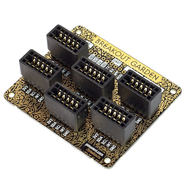
Pimoroni Pimoroni Breakout Garden for Raspberry Pi (I²C)
Thanks to its six sturdy slots, Breakout Garden enables the users to simply plug and play with various tiny breakout board.Just insert one or more boards into the slots in the Breakout Garden HAT and you’re ready to go. The mini breakouts feel secure enough in the edge-connector slots and are very unlikely to fall out.There are a number of useful pins along the top of Breakout Garden, which lets you connect other devices and integrate them into your project.You shouldn't be worried if you insert a board the wrong way thanks to provided reverse polarity protection. It doesn't matter which slot you use for each breakout either, because the I²C address of the breakout will be recognised by the software and it'll detect them correctly in case you move them around.Features Six sturdy edge-connector slots for Pimoroni breakouts 0.1” pitch, 5 pin connectors Broken-out pins (1 × 10 strip of male header included) Standoffs (M2.5, 10 mm height) included to hold your Breakout Garden securely Reverse polarity protection (built into breakouts) HAT format board Compatible with Raspberry Pi 3 B+, 3, 2, B+, A+, Zero, and Zero W It's suggested using the included standoffs to attache Breakout Garden to your Raspberry Pi.SoftwareBreakout Garden doesn't require any software of its own, but each breakout you use will need a Python library. On the Breakout Garden GitHub page you'll find an automatic installer, which will install the appropriate software for a given breakout. There are also some examples that show you what else you can do with Breakout Garden.
€ 19,95€ 7,98
Leden identiek
-
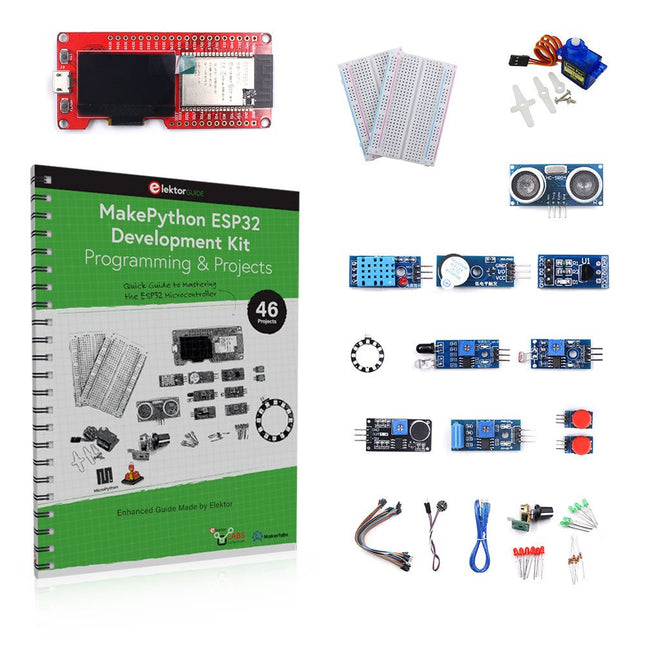
Elektor Bundles MakePython ESP32 Development Kit
Leer hoe je de ESP32 Microcontroller en het programmeren met MicroPython in je toekomstige projecten kunt gebruiken! Het (Engelstalige) projectboek, geschreven door de bekende Elektor auteur Dogan Ibrahim, bevat vele software- en hardware-gebaseerde projecten die speciaal voor de MakePython ESP32 ontwikkelkit ontwikkeld zijn. De kit wordt geleverd met verschillende LED's, sensoren, en actuatoren. De kit helpt je de basiskennis op te doen om eigen IoT projecten te maken. Alle volledig geëvalueerde projecten in het boek zijn voorzien van de bijgeleverde componenten. Elk project bevat een blokschema, een schakelschema, een volledige programmalijst, en een volledige programma beschrijving. Inbegrepen in de kit 1x MakePython ESP32 ontwikkelingsboard met LCD 1x Ultrasone afstandsmeter 1x Temperatuur- en luchtvochtigheidssensor 1x Zoemer module 1x DS18B20 module 1x Infrarood module 1x Potentiometer 1x WS2812 module 1x Geluidssensor 1x Trilsensor 1x Module met lichtgevoelige weerstand 1x Puls sensor 1x Servo motor 1x USB kabel 2x Knop 2x Breadboard 45x Schakeldraad 10x Weerstand 330R 10x LED (Rood) 10x LED (Groen) 1x Projectboek (Engelstalig, 206 pagina's) Boek met 46 projecten LED Projecten Knipperende LED SOS knipperende LED Knipperende LED – met behulp van een timer Afwisselend knipperende LEDs Knopbediening De knippersnelheid van de LED's veranderen met drukknop onderbrekingen Chasing-LEDs Binaire teller met LEDs Kerstverlichting (willekeurig-knipperende 8 LEDs) Elektronische dobbelsteen Geluksdag van het week Projecten voor Pulsewidth Modulation (PWM) Genereer een PWM golfvorm van 1000 Hz met 50% duty cycle LED helderheid regelen Meten van de frequentie en duty cycle van een PWM golfvorm Melodieën maker Eenvoudig elektronisch orgel Servo motor besturing Servo motor DS18B20 thermometer Projecten voor analoog naar digitaal converteren (ADC) Voltmeter Plotten van de analoge ingangsspanning Interne temperatuursensor van de ESP32 Ohmmeter Lichtgevoelige weerstandsmodule Projecten voor digitaal naar analoog converteren (DAC) Opwekken van vaste spanningen Opwekken van een zaagtand-golf signaal Opwekken van een driehoek-golf signaal Golfvorm met willekeurige periode Genereren van een sinus-golf signaal Genereren van een nauwkeurig sinus-golf signaal met behulp van een timer interrupts Gebruik van het OLED Display Seconden teller Gebeurtenisteller DS18B20 digitale thermometer met OLED ON-OFF temperatuur regelaar Meten van temperatuur en luchtvochtigheid Ultrasone afstandsmeting Hoogte van een persoon (stadiometer) Hartslag (polsslag) meten Andere bij de set geleverde sensoren Diefstal alarm Met geluid geactiveerd licht Infrarood obstakel-vermijding met zoemer WS2812 RGB LED ring Tijdregistratie van temperatuur en luchtvochtigheid Netwerkprogrammering Wi-Fi scanner Bediening op afstand vanuit de Internet browser (met een smartphone of PC) – Webserver Temperatuur- en luchtvochtigheidsgegevens opslaan in de Cloud Werking met Low-Power Gebruik een timer om de processor te laten ontwaken
€ 89,95€ 64,95
Leden identiek
-
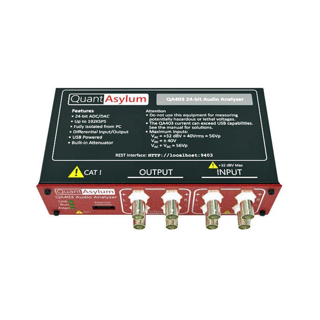
QuantAsylum QuantAsylum QA403 24-bit Audio Analyzer
De QA403 is de vierde generatie audio analyzer van QuantAsylum. Deze QA403 verhoogt de functionaliteit van de QA402 met verbeterde ruis- en vervormingsprestaties, en ook een vlakkere respons aan de randen van de band. Het compacte formaat van de QA403 zorgt ervoor dat u hem vrijwel overal mee naartoe kunt nemen. Kenmerken 24-bits ADC/DAC Tot 192 kS/s Volledig geïsoleerd van de PC Differentiële input/output USB gevoed Ingebouwde demping Snel opstarten en geen stuurprogramma De QA403 is een USB-apparaat zonder stuurprogramma's, wat betekent dat hij meteen operationeel is zodra u hem aansluit. De software is gratis, en u kunt snel en gemakkelijk de hardware van de ene machine naar de andere verplaatsen. Dus als u naar een vestiging moet om een probleem op te lossen, of de QA403 mee naar huis dient te nemen op een thuiswerkdag, dan kunt u dit zonder veel gedoe doen. No-Cal ontwerp De QA403 wordt geleverd met een fabriekskalibratie in het flashgeheugen, waardoor consistente prestaties bij gebruik van meerdere analyzers kan worden gegarandeerd. Op uw productielijn kunt u een andere QA403 installeren en erop vertrouwen dat wat u op de ene analyzer leest overeenkomt met de andere. Er hoeft dus niet geregeld herkalibratie plaats te vinden. Metingen Het uitvoeren van basismetingen kan snel en eenvoudig. In een paar klikken krijgt u inzicht in de frequentierespons, de THD (+ N), de versterking, de SNR, en andere gegevens van uw geteste apparaat. Dynamisch bereik De QA403 biedt 8 gradaties aan versterking op de ingang (0 tot +42 dBV in 6 stappen) en 4 stappen versterking op de uitgang (-12 tot +18 dBV in stappen van 10 dB). Dit zorgt voor consistente prestaties over zeer brede in- en uitgangsniveaus. De maximale AC ingangsspanning op de QA403 is +32 dBV = 40 Vrms. De maximale DC is ±40 V en de maximale ACPEAK + DC = ±56 V. Eenvoudig te programmeren De QA403 ondersteunt een REST-interface, waardoor het eenvoudig is om metingen te automatiseren in vrijwel elke taal. Van Python tot C++ tot Visual Basic: als u weet hoe u een webpagina in uw favoriete taal moet laden dan kunt u al de QA403 op afstand bedienen. Metingen zijn snel en responsief, doorgaans met het verwerken van tientallen opdrachten per seconde. Geïsoleerd, en gevoed via USB De QA403 werkt geïsoleerd van de pc, wat betekent dat u echt uw te testen apparaat meet, en niet met een fantoom aardlus te doen heeft. De QA403 wordt gevoed via USB, zoals bijna alle QuantAsylum instrumenten. Indien u op afstand moet configureren, neem dan een hub met voeding mee in uw tas en uw hele testopstelling kan dan functioneren met een minimum aan kabels. Vaarwel geluidskaart, hallo QA403 Moe van het proberen om een geluidskaart aan de praat te krijgen? Nachtmerries van het kalibreren? Gemis van de juiste versterking? Of te weinig aansturing? Bent u het zat om met vaste ingangsranges om te gaan? Of bang dat u zaken kapot maakt met te veel DC of AC? Moe van de aardlussen? Dáarom heeft QuantAsylum de QA403 ontworpen. Specificaties Afmetingen 177 x 44 x 97 mm (B x H x D) Gewicht 435 g Case Materiaal Aluminium met poedercoating (2 mm dik voorpaneel, 1.6 mm dikke boven/onderkant) Downloads Datasheet Manual GitHub
€ 799,00
Leden € 719,10


