Trade products
-

OWON OWON HDS2102s (3-in-1) 2-kanaals Oscilloscoop (100 MHz) + Multimeter + Signaalgenerator
De OWON HDS2102s is een draagbare 3-in-1 multifunctionele tester, die kan worden gebruikt als een 2-kanaals oscilloscoop met een bandbreedte van 100 MHz, multimeter en signaalgenerator. Het beschikt over een contrastrijk 3,5-inch kleurendisplay dat geschikt is voor onderhoud van buitenfaciliteiten, snelle metingen op locatie, onderhoud van auto's, stroomdetectie, enz. Kenmerken Oscilloscope + multimeter + waveform generator, multifunction in one 3.5-inch high-resolution, high-contrast color LCD display, suitable for outdoor use 18650 lithium battery, can work continuously for 3-6 hours USB Type-C interface, support power bank, support PC software connection Self-calibration function SCPI supported, facilitate secondary development Specificaties Bandwidth 100 MHz Channels 2-ch Oscilloscope + 1-ch Generator Sample Rate 500 MSa/s Acquisition Model Normal, Peak detect Record Length 8K Display 3.5-inch LCD Waveform Refresh Rate 10,000 wfrms/s Input Coupling DC, AC, and Ground Input Impedance 1 MΩ ±2%, in parallel with 16pF ±10pF Probe Attenuation Factors 1X,10X,100X,1000X,10000X Max. input Voltage 400 V (DC+AC, PK-PK, 1MΩ input impedance) (10:1 probe attenuation) Bandwidth Limit (typical) 20 MHz Horizontal Scale 2ns/div - 1000s/div, step by 1 - 2 - 5 Vertical Sensitivity 10mV/div - 10V/div Vertical Resolution 8 bits Trigger Type Edge Trigger Modes Auto, Normal, single Automatic Measurement Frequency, Period, Amplitude, Max, Min, Mean, PK-PK Cursor Measurement ΔV, ΔT, ΔT&ΔV between cursors Communication Interface USB-C Multimeter (Specificaties) Max. Resolution 20,000 counts Testing Mode Voltage, Current, Resistance, Capacitance, Diode, and Continuity test Input Impedance 10 MΩ Max Input Voltage AC 750 V, DC 1000 V Max Input Current DC: 10 A, AC: 10 A Diode 0-2 V Signaalgenerator (Specificaties) Frequency Output Sine 0.1 Hz - 25 MHz Square 0.1 Hz - 5MHz Ramp 0.1 Hz - 1 MHz Pulse 0.1 Hz - 5 MHz Arbitrary 0.1 Hz - 5 MHz Sampling Rate 125 MSa/s Channel 1-ch Amplitude Range (high impedance) 20 mVpp - 5 Vpp Waveform Length 8K Vertical Resolution 14 bits Output Impedance 50Ω Inbegrepen 1x OWON HDS2102s Oscilloscope 1x Power adapter 1x USB cable 1x Passive probes 2x Crocodile clip cable 1x Set of multimeter probes (one red and one black) 1x User manual 1x Probe correction adjustment knife Downloads User Manual Specifications SCPI Protocol Quick Guide Software
€ 187,57
-

Siglent Siglent SDM3045X True RMS Multimeter
De Siglent SDM3045X is een 4½ digit digitale (66000 counts, sampling rate 150 Sa/s) multimeter met een dual-display, en is bijzonder geschikt voor het doen van zeer nauwkeurige, multifunctionele en automatische metingen. Vanwege zijn grote 4,3' (10,9 cm) TFT kleurendisplay (480x272 pixels) is de navigatie door de menu’s zeer intuïtief en erg gemakkelijk afleesbaar. Kenmerken Een echte 4½ digit digitale (66000 counts) meetresolutie Tot maximaal 150 rdgs/s meetsnelheid True-RMS AC spanning en AC stroom metingen 1 GB NAND-flash, configuratiebestanden voor massaopslag en databestanden Ingebouwde cold terminal compensation voor thermokoppel Met eenvoudige, handige en flexibele PC-software: EasyDMM Standaard interface: USB Device, USB Host, LAN USB &LAN externe interfaces ondersteunen gemeenschappelijke SCPI commando set. Compatibel met andere populaire DMM's op de markt. Toepassingen Onderzoekslaboratorium Ontwikkellaboratorium Detectie en onderhoud Kalibratie Laboratorium Automatische productietest Meetfuncties DC spanning: 600 mV – 1000 V DC stroom: 600 ?A – 10 A AC spanning: True-RMS, 600 mV – 750 V AC stroom: True-RMS, 60 mA – 10 A 2/4-draads weerstand: 600 ? – 100 M ? Capaciteit: 2 nF – 10000 ?F Continuïteitstest: Bereik vast ingesteld op 2 k? Diode test: Bereik instelbaar van 0-4 V Frequentiemeting: 20 Hz – 500 KHz Periode meting: 2 ?s – 0,05 s Temperatuur: Ondersteuning voor TC- en RTD-sensor Max, Min, Gemiddelde, Standaarddeviatie, dBm/dB, Relatieve Meting, Pass/Fail, Histogram, Trend chart Kenmerken DC spanning 200 mV, 2 V, 20 V, 200 V, 1000 V DC stroom 200 ?A, 2 mA, 20 mA, 200 mA, 2 A, 10 A AC spanning True-RMS, 200 mV, 2 V, 20 V, 200 V, 750 V AC stroom True-RMS, 20 mA, 200 mA, 2 A, 10 A 2/4-draads weerstand 200 ?, 2 K, 20 K, 200 K, 2 M, 10 M, 100 M? Capaciteit 2 nF, 20 nF, 200 nF, 2 ?F, 20 ?F, 200 ?F, 10000 ?F Continuïteitstest Bereik is vast ingesteld op 2 k? Diode test Bereik instelbaar van 0-4 V Frequentiemeting 20 Hz ~ 1 MHz Periode meting 1 ?s ~ 0.05 s Temperatuur Ondersteuning van thermocouple, RTD temperature sensor Maximum input spanning 1000 V Configuratie Interface USB Device, USB Host, LAN Inbegrepen 1x Siglent SDM3065X Multimeter 1x USB kabel 2x multimeter probes 1x netstroom kabel 1x Quick Start Guide Downloads User Manual Datasheet Remote Manual Service Manual
€ 435,33
-

Zhongdi ZD-129A Magnifying LED Desk Lamp
Deze bureaulamp is ideaal voor op uw werkplek. Met de 5-inch 5D-lens kunnen de subtielste klusjes worden gedaan. De lamp heeft 80 geïntegreerde leds. Kenmerken Lens grootte: 5 inch Lens materiaal: glas Dioptrie: 5D Lichtbron: T5 22 W fluorescentielamp (80 stuks leds) Spanning: 220-240 V Vermogen: 22 W
€ 50,00
-
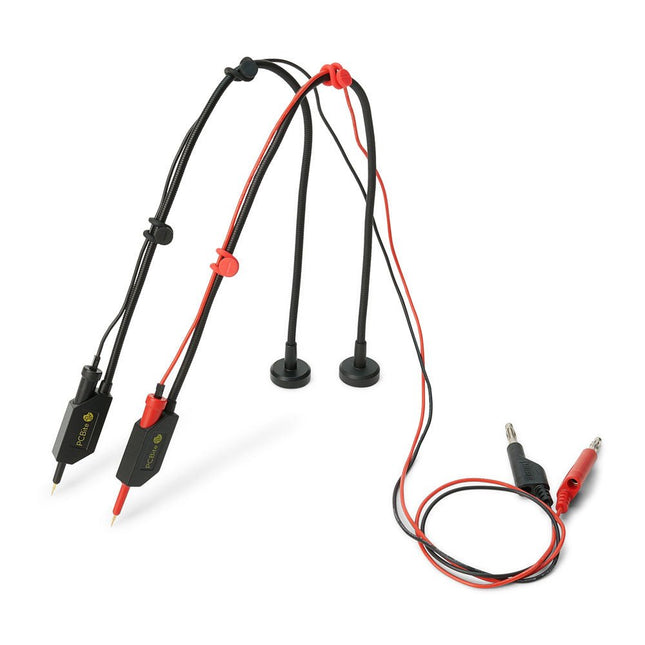
Sensepeek Sensepeek 6011 2x SQ10 Probe for DMM (red/black)
The SQ series of handsfree PCBite probes from Sensepeek are insulated, come with included color-coded cable holders and have a lower point of gravity making them even more stable compared with the original SP series of probes. All the loved features of handsfree measurement, exchangeable fine pitch spring tipped test needle and the minimalistic design is maintained to make traditional sized and handheld probes obsolete. Features All handsfree probes from Sensepeek makes instant measurements or long triggering sessions a breeze. No more soldering wires to connect your probe or complicated tools to setup, just positioning the probe needle on any test point or component in the signal path and release. Saves time and frustration during development, verification and repairs. The minimalist design and the spring-loaded test needle makes it possible to simultaneously measure on fine pitch components and nearby signals. Both length and weight of the SQ probes are perfectly balanced to be used with PCBite PCB holders and base plate which is a must for handsfree function. The probe holder comes with a powerful magnet in the base, as for all PCBite probes and holders which makes the probe easy to place and reposition. The SQ series of probes can be used handheld without the probe holder as they have an insulated grip but their full potential is used when measuring handsfree. Included 2x SQ10 probes and pin tipped test needles (red/black) 2x Banana to dupont test wires (red/black) 1x Set of cable holders (red/black) 2x Extra test needles Downloads User guide
€ 54,45
-
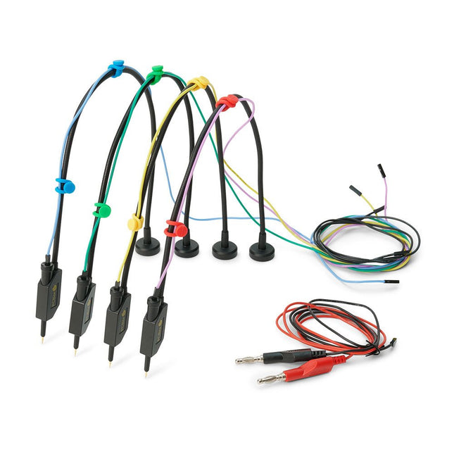
Sensepeek Sensepeek 6005 4x SQ10 Probe incl. Test Wires
The SQ series of handsfree PCBite probes from Sensepeek are insulated, come with included color-coded cable holders and have a lower point of gravity making them even more stable compared with the original SP series of probes. All the loved features of handsfree measurement, exchangeable fine pitch spring tipped test needle and the minimalistic design is maintained to make traditional sized and handheld probes obsolete. Features All handsfree probes from Sensepeek makes instant measurements or long triggering sessions a breeze. No more soldering wires to connect your probe or complicated tools to setup, just positioning the probe needle on any test point or component in the signal path and release. Saves time and frustration during development, verification and repairs. The minimalist design and the spring-loaded test needle makes it possible to simultaneously measure on fine pitch components and nearby signals. Both length and weight of the SQ probes are perfectly balanced to be used with PCBite PCB holders and base plate which is a must for handsfree function. The probe holder comes with a powerful magnet in the base, as for all PCBite probes and holders which makes the probe easy to place and reposition. The SQ series of probes can be used handheld without the probe holder as they have an insulated grip but their full potential is used when measuring handsfree. Included 4x SQ10 probes and pin tipped test needles (black) 2x Banana to dupont test wires (red/black) 5x Dupont to dupont test wires 1x Set of cable holders (4 colors) 4x Extra test needles Downloads User guide
€ 107,69
-

SDRplay SDRplay RSP1B 14-bit SDR-ontvanger (1 kHz tot 2 GHz)
De SDRplay RSP1B is een verbeterde versie van de populaire RSP1A – een krachtige, breedbandige, complete 14-bits SDR die het RF-spectrum van 1 kHz tot 2 GHz bestrijkt. De RSP1B is uitgevoerd in een robuuste, zwartgelakte stalen behuizing en biedt aanzienlijk verbeterde ruisprestaties. Het enige wat nodig is, is een computer en een antenne voor uitstekende communicatie- en ontvangstfunctionaliteit. Het wordt geleverd met SDRuno voor Windows en de multi-platform SDRconnect-software voor Windows, macOS en Linux (gratis geleverd door SDRplay). U kunt tot 10 MHz spectrum tegelijk monitoren. Een gedocumenteerde API stelt ontwikkelaars in staat om nieuwe demodulatoren of applicaties voor het platform te creëren. Kenmerken Covers all frequencies from 1 kHz through VLF, LF, MW, HF, VHF, UHF and L-band to 2 GHz, with no gaps Receive, monitor and record up to 10 MHz of spectrum at a time Free use of windows-based SDRuno software which provides an ever-increasing feature-set Strong and growing software support network Calibrated S meter/ RF power and SNR measurement with SDRuno (including datalogging to .CSV file capability) Documented API provided to allow demodulator or application development on multiple platforms Excellent dynamic range for challenging reception conditions Works with popular 3rd party SDR software (including HDSDR, SDR Console and Cubic SDR) ExtIO based plugin available Software upgradeable for future standards Strong and growing software support network API provided to allow demodulator or application development Multiplatform driver and API support including Windows, Linux, Mac, Android and Raspberry Pi Up to 16 individual receivers in any 10 MHz slice of spectrum using SDRuno Calibrated S meter and power measurements with SDRuno Stand-alone windows-based spectrum analyser software available (with sweep, sample and hold features) Ideal for monitoring of ISM/IoT/Telemetry bands <2 GHz Ideal for portable operation Specificaties Frequency Range 1 kHz – 2 GHz Antenna Connector SMA Antenna Impedance 50 Ohms Current Consumption (Typical) 185 mA (excl. Bias-T) USB Connector USB Type B Maximum Input Power +0 dBm Continuous+10 dBm Short Duration ADC Sample Rates 2-10.66 MSPS ADC Number of Bits 14 bit 2-6.048 MSPS12 bit 6.048-8.064 MSPS10 bit 8.064-9.216 MSPS8 bit >9.216 MSPS Bias-T 4.7 V100 mA guaranteed Reference 0.5ppm 24 MHz TCXO.Frequency error trimmable to 0.01ppm in field. Operating Temperature Range -10✓C to +60✓C Dimensions 98 x 88 x 34 mm Weight 110 g Downloads Datasheet Software RSP1B vs RSPdx vs RSPduo RSP1B RSPdx RSPduo Continuous coverage from 1 kHz to 2 GHz ✓ ✓ ✓ Up to 10 Mhz visible bandwidth ✓ ✓ ✓ 14-bit ADC silicon technology plus multiple high-performance input filters ✓ ✓ ✓ Software selectable AM/FM & DAB broadcast band notch filters ✓ ✓ ✓ 4.7 V Bias-T for powering external remote antenna amplifier ✓ ✓ ✓ Powers over the USB cable with a simple type B socket ✓ ✓ ✓ 50✓ SMA antenna input(s) for 1 kHz to 2 GHz operation (software selectable) 1 2 2 Additional software selectable Hi-Z input for up to 30 Mhz operation ✓ Additional software selectable 50✓ BNC input for up to 200 MHz operation ✓ Additional LF/VLF filter for below 500 kHz ✓ 24 MHz reference clock input (+ output on RSPduo) ✓ ✓ Dual tuners enabling reception on 2 totally independent 2 MHz ranges ✓ Dual tuners enabling diversity reception using SDRuno ✓ Robust and strong plastic case (with internal RF shielding layer) ✓ Rugged black painted steel case ✓ ✓ Overall performance below 2 MHz for MW and LF + ++ + Multiple simultaneous applications + + ++ Performance in challenging fading conditions (*using diversity tuning) + + *++
€ 148,99
-

Raspberry Pi Foundation FPC Display Cable for Raspberry Pi 5 (300 mm)
Raspberry Pi 5 provides two four-lane MIPI connectors, each of which can support either a camera or a display. These connectors use the same 22-way, 0.5 mm-pitch “mini” FPC format as the Compute Module Development Kit, and require adapter cables to connect to the 15-way, 1 mm-pitch “standard” format connectors on current Raspbery Pi camera and display products.These mini-to-standard adapter cables for cameras and displays (note that a camera cable should not be used with a display, and vice versa) are available in 200 mm, 300 mm and 500 mm lengths.
€ 2,95€ 1,18
Beste prijs
-
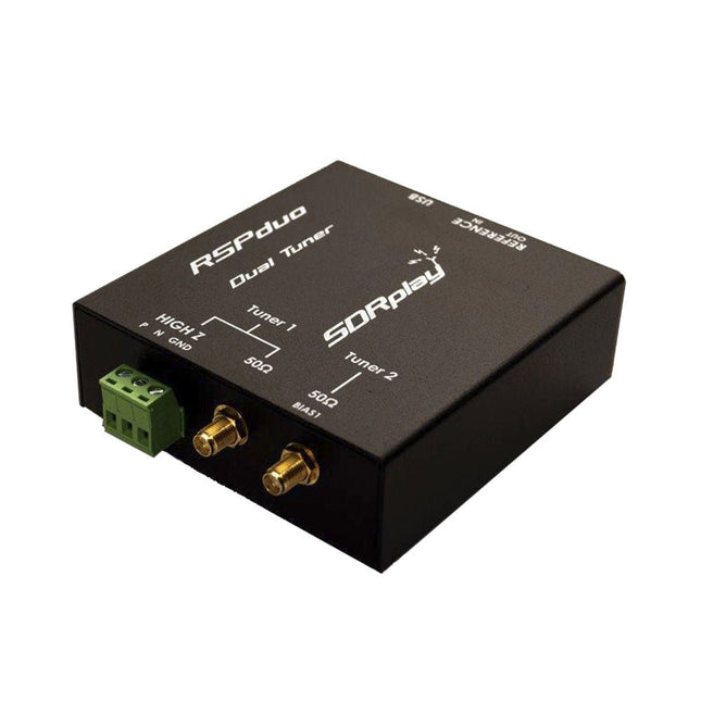
SDRplay SDRplay RSPduo Dual-Tuner 14-bit SDR-ontvanger (1 kHz tot 2 GHz)
De SDRplay RSPduo is een hoogwaardige 14-bit SDR-ontvanger met dubbele tuner. De tuner is ondergebracht in een hoogwaardige stalen behuizing en kan afzonderlijk werken tussen 1 kHz en 2 GHz met een bandbreedte tot 10 MHz. Beide tuners kunnen tegelijkertijd werken tussen 1 kHz en 2 GHz met een bandbreedte tot 2 MHz per tuner. Een zeer stabiele referentie en externe klokfuncties maken dit apparaat ideaal voor industriële, wetenschappelijke en educatieve toepassingen. Kenmerken Dubbele tuner biedt onafhankelijke dekking van 1 kHz tot 2 GHz met behulp van 2 antennepoorten tegelijk 14-bits ADC-siliciumtechnologie Tot 10 MHz zichtbare bandbreedte (enkele tunermodus) of 2 slices van 2 MHz spectrum (dubbele tunermodus) 3 softwarematig selecteerbare antennepoorten (2x 50Ω en 1x 1kΩ hoge impedantie gebalanceerde/ongebalanceerde ingang) Antennepoort met hoge impedantie (1 kHz tot 30 MHz) met selecteerbaar MW-notchfilter en keuze uit 2 voorselectiefilters Softwarematig selecteerbare AM/FM- en DAB-uitzendband-notchfilters voor de 2 SMA-antennepoorten (1 kHz tot 2 GHz) Externe klokinvoer en -uitvoer maken eenvoudige synchronisatie met meerdere RSP's of een externe referentieklok mogelijk Wordt gevoed via de USB-kabel met een eenvoudige type B-aansluiting 11 hoogselectieve, ingebouwde front-end preselectiefilters op beide 2 SMA-antennepoorten Softwarematig selecteerbare multi-level Low Noise voorversterker Bias-T voeding voor het voeden van een op de antenne gemonteerde LNA In een robuuste, zwart gelakte stalen behuizing. SDRuno – SDR-software van wereldklasse voor Windows Gedocumenteerde API voor de ontwikkeling van nieuwe apps Specificaties Frequentiebereik 1 kHz – 2 GHz Antenne-aansluiting SMA Antenne-impedantie 50 ohm Stroomverbruik (typisch) Enkele tunermodus: 180 mA (excl. Bias-T)Dubbele tunermodus: 280 mA (excl. Bias-T) USB-aansluiting USB type B Maximaal ingangsvermogen +0 dBm Continu+10 dBm korte duur ADC-samplefrequenties 2-10,66 MSPS ADC-aantal bits 14 bit 2-6,048 MSPS12 bit 6,048-8,064 MSPS10 bit 8,064-9,216 MSPS8 bit >9,216 MSPS Bias-T 4,7 V100 mA gegarandeerd Referentie Hoge temperatuurstabiliteit (0,5 ppm) 24 MHz TCXOFrequentiefout instelbaar tot 0,01 ppm in het veld Bedrijfstemperatuurbereik −10°C tot +60°C Afmetingen 98 x 94 x 33 mm Gewicht 315 g Downloads Datasheet Detailed Technical Information Software RSPdx-R2 vs RSPduo RSPdx-R2 RSPduo Continue dekking van 1 kHz tot 2 GHz ✓ ✓ Tot 10 MHz zichtbare bandbreedte ✓ ✓ 14-bits ADC siliciumtechnologie plus meerdere krachtige ingangsfilters ✓ ✓ Softwarematig selecteerbare AM/FM & DAB broadcast band notch filters ✓ ✓ 4,7 V Bias-T voor voeding van externe antenneversterker ✓ ✓ Voedt de USB-kabel met een eenvoudige aansluiting type B ✓ ✓ 50Ω SMA-antenne-ingang(en) voor werking van 1 kHz tot 2 GHz (softwarematig instelbaar) 2 2 Extra softwarematig selecteerbare Hi-Z ingang voor werking tot 30 MHz ✓ Extra softwarematig selecteerbare 50Ω BNC-ingang voor werking tot 200 MHz ✓ Extra LF/VLF-filter voor onder 500 kHz ✓ 24 MHz referentieklokingang (+ uitgang op RSPduo) ✓ ✓ Dubbele tuners voor ontvangst op 2 totaal onafhankelijke 2 MHz-bereiken ✓ Dubbele tuners voor diversiteitsontvangst met SDRuno ✓ Robuuste zwartgelakte stalen behuizing ✓ ✓ Algemene prestaties onder 2 MHz voor MW en LF ++ + Meerdere gelijktijdige toepassingen + ++ Prestaties in uitdagende fading-omstandigheden (*met gebruik van diversiteitsafstemming) + *++
€ 287,98
-

OWON OWON SPE6103 DC Power Supply (300 W)
The OWON SPE6103 is a 1-channel DC power supply (300 W) in a small body with features like over voltage and over current protection. It has a high resolution of 10 mV/1 mA. The 2.8' LCD displays the following information (constant voltage output, constant current output, cumulative running time, actual output power, channel output status, actual voltage output, actual current output).Features Small body for easy carry High resolution: 10 mV/1 mA List waveform editing output, editable 10 groups of timing output function Low ripple/noise Over voltage / over current protection Output voltage and current curve monitoring function Intelligent temperature control fan cooling 2.8-inch TFT LCD display USB communication interface, support SCPI Specifications Model SPE6102 SPE6103 Rated Output (0-40°C) Voltage 0-60 V 0-60 V Current 10 A 10 A Output Power 200 W 300 W USB Output 5 V/1 A (SPE Series) or suppout QC2.0, QC3.0, BC1.2, Apple, Huawei, Samsung fast charging protocols (optional) Load Regulation Voltage ?30 mV Current ?20 mA Power Regulation Voltage ?30 mV Current ?20 mA Setting Resolution Voltage 10 mV Current 1 mA Readback Resolution Voltage 10 mV Current 1 mA Value Resolution (within 12 months) (25 ±5°C) Voltage ?0.1% ±30 mV ?0.1% ±30 mV Current ?0.05% ±10 mA Readback Value Resolution (25 ±5°C) Voltage ?0.1% ±30 mV ?0.1% ±30 mV Current Ripple/Noise Voltage (Vp-p) ?50mVp-p ?50mVp-p Voltage (rms) ?5mVrms ?5mVrms Current (rms) ?30mAp-p Output temperature coefficient (0-40°C) Voltage 100ppm/°C Current 200ppm/°C Readback temperature coefficient Voltage 100ppm/°C Current 200ppm/°C Response Time (50-100% rated load) ?1.0ms Storage 4 groups of data Working Temperature 0-40°C Included 1x OWON SPE6102 1x Power Cord 1x Quick Guide 1x USB Cable 1x Fuse Downloads User Manual Programming Manual Software
€ 125,00
-

OWON OWON OW18B Bluetooth Multimeter
Features Data-logger & Multimeter & Thermometer 3 (5/6) digits True RMS test supported BLE 4.0 wireless transmission, more stable, less power consumption Chart and Diagram mode, to analyze your data Supports NCV Voice Broadcast simplifies testing Flashlight function Built-in offline recording function Supports Android, iOS Included Test leads K-type thermocouple 9 V Battery Bolt driver Crocodile clip Quick guide
€ 39,63
-

Uni-Trend UNI-T UDP3305S-E DC-voeding (328 W)
The UDP3305S-E is a high-performance programmable linear DC power supply. It has a clear LCD user interface, excellent performance indicators, a variety of analysis functions and communication interfaces. It can meet the diversified test needs of users. It aims to provide cost-effective DC programmable power supply equipment for teaching, scientific research, industry and other fields. LCD interactive interface Using a 4.3-inch high-definition display screen, it provides users with a man-machine interface with rich functions and simple operation, which can display the current set output voltage/current, actual output voltage/current and protection output voltage/current value of the power supply in real time. The functional interface is simple and comprehensive, easy to operate. One-key setting for series and parallel The series-parallel connection between CH1 and CH2 of the main channel can be realized without external connection, which simplifies the connection and makes the test easier. List/Delayer function With list and delay setting functions, it can set up to 2048 sets of data according to test requirements, and the number of cycles can reach 99999. It is used with waveform templates, which is very convenient for cycle testing and aging testing. Rich remote control interface Standard RS232 communication interface, Ethernet interface, Digital I/O and master and slave USB interfaces, can be controlled by remote connection to Ethernet, or through RS232 and USB, with the host computer software to achieve software control. Specificaties Type Linear DC power supply Channels 4 Total power 328 W Output voltage CH1/CH2: 0~30 VCH3: 0~6 VCH4: 5 V Output current CH1/CH2: 0~5 ACH3: 0~3 ACH4: 2 A Resolution 10 mV, 1 mA Setting accuracy 0.3% +20 mV<0.2% +5 mA Connectivity USB Device, RS-232, LAN, USB host, Digital I/O Inbegrepen 1x UDP3305S-E DC Power Supply 1x Power cord 1x USB cable Downloads Datasheet User manual Programming manual Software V1.0 Firmware V1.10
€ 396,54
-

SunFounder Universal Maker Sensor Kit (voor Raspberry Pi, Pico W, Arduino, ESP32)
Ontdek eindeloze creativiteit met de Universal Maker Sensor Kit, ontworpen voor gebruik met Raspberry Pi, Pico W, Arduino en ESP32. Deze veelzijdige kit biedt compatibiliteit met populaire ontwikkelingsplatforms, waaronder Arduino Uno R4 Minima/WiFi, Uno R3, Mega 2560, Raspberry Pi 5, 4, 3B+, 3B, Zero, Pico W en ESP32. Met meer dan 35 sensoren, actuatoren en displays is het perfect voor projecten variërend van omgevingsmonitoring en slimme huisautomatisering tot robotica en interactief gamen. Stapsgewijze tutorials in C/C++, Python en MicroPython begeleiden zowel beginners als ervaren makers door 169 spannende projecten. Kenmerken Brede compatibiliteit: Ondersteunt volledig Arduino (Uno R3, Uno R4 Minima/WiFi, Mega 2560), Raspberry Pi (5, 4, 3B+, 3B, Zero, Pico W) en ESP32, wat uitgebreide flexibiliteit op verschillende ontwikkelingsplatforms mogelijk maakt. Bevat instructies voor het bouwen van 169 projecten. Uitgebreide componenten: Bevat meer dan 35 sensoren, actuatoren en displaymodules die geschikt zijn voor uiteenlopende projecten zoals omgevingsbewaking, slimme huisautomatisering, robotica en interactieve gamecontrollers. Gedetailleerde tutorials: Biedt duidelijke, stapsgewijze tutorials over Arduino, Raspberry Pi, Pico W, ESP32 en elk inbegrepen component. Tutorials zijn beschikbaar in C/C++, Python en MicroPython, en zijn effectief afgestemd op zowel beginners als ervaren makers. Geschikt voor alle vaardigheidsniveaus: Biedt gestructureerde projecten die zijn ontworpen om gebruikers naadloos te begeleiden van beginners tot gevorderden in elektronica en programmeren, wat de creativiteit en technische expertise vergroot. Inbegrepen Breadboard Knopmodule Capacitieve bodemvochtigheidsmodule Vlamsensormodule Gas-/rooksensormodule (MQ2) Gyroscoop & Accelerometermodule (MPU6050) Hall-sensormodule Infraroodsnelheidssensormodule IR-obstakelvermijdingssensormodule Joystickmodule PCF8591 ADC DAC-convertermodule Fotoweerstandsmodule PIR-bewegingsmodule (HC-SR501) Potentiometermodule Pulsoximeter- en hartslagsensormodule (MAX30102) Regendruppeldetectiemodule Realtimeklokmodule (DS1302) Rotary Encoder-module Temperatuursensormodule (DS18B20) Temperatuur- en vochtigheidssensormodule (DHT11) Temperatuur, vochtigheid en Druksensor (BMP280) Time of Flight Micro-LIDAR afstandssensor (VL53L0X) Touch Sensor Module Ultrasone sensormodule (HC-SR04) Trillingssensormodule (SW-420) Waterniveausensormodule I²C LCD 1602 OLED-displaymodule (SSD1306) RGB LED-module Verkeerslichtmodule 5 V relaismodule Centrifugaalpomp L9110 motordrivermodule Passieve zoemermodule Servomotor (SG90) TT Motor ESP8266-module JDY-31 Bluetooth-module Voedingsmodule Documentatie Online Tutorial
-

iFixit iFixit Essential Electronics Toolkit
De iFixit Essential Electronics Toolkit is precies wat u nodig heeft voor de meest essentiële elektronische reparaties – zoals het vervangen van schermen en batterijen – én voor de meeste doe-het-zelfklussen in en om het huis. Ga direct aan de slag met elektronica reparaties dankzij alle bits en precisiegereedschappen die u nodig heeft om uw meest urgente schermbreuken en batterijvervangingen aan te pakken. Of breid eenvoudig uw doe-het-zelfgereedschap voor thuis uit met alles wat u nodig heeft voor het onderhouden van deurknoppen, huishoudelijke apparaten, brillen en nog veel meer. Kit bevat Magnetized Driver Handle Angled Precision Tweezers Spudger Jimmy iFixit Opening Tool iFixit Opening Picks set of 6 Suction Handle Easy-to-Open Magnetized Case Lid with Built-in Sorting Tray Sixteen 4mm Precision Screwdriver Bits Phillips - 000, 00, 0, 1 Pentalobe - P2, P5 Flathead - 1 mm, 2.5 mm, 4 mm Torx - T4, T5 Torx Security - TR6, TR8, TR10 Tri-Point - Y000 SIM Eject Bit Specificaties Bit Metal: 6150 Steel Driver Material: Polymer Case Material: ABS Foam: EVA
€ 34,95
-

Raspberry Pi Foundation FPC Display Cable for Raspberry Pi 5 (500 mm)
Raspberry Pi 5 provides two four-lane MIPI connectors, each of which can support either a camera or a display. These connectors use the same 22-way, 0.5 mm-pitch “mini” FPC format as the Compute Module Development Kit, and require adapter cables to connect to the 15-way, 1 mm-pitch “standard” format connectors on current Raspbery Pi camera and display products.These mini-to-standard adapter cables for cameras and displays (note that a camera cable should not be used with a display, and vice versa) are available in 200 mm, 300 mm and 500 mm lengths.
€ 3,95€ 1,58
Beste prijs
-

Miniware Miniware MDP-P906 Digital Power Supply (300 W)
De MDP-P906 heeft een ingebouwde ventilator en een maximaal uitgangsvermogen van 300 W, wat toereikend is voor een breed scala aan testbehoeften en toepassingen. Via 2,4 GHz draadloze communicatie kan hij worden aangesloten op de MDP-M01 Smart Digital Monitor module om daarmee een flexibele combinatie van meerdere kanalen van 300 W per kanaal te kunnen realiseren. De MDP-P906 heeft een basis, stabiliteit en betrouwbaarheid die te vergelijken is met een professionele voeding. Hij kan puur stroom leveren én krachtige functies hieraan toevoegen, zoals programmeerbare uitgang, getimede uitgang, getimede regeling, automatische compensatie, boost modus, enz. Dit maakt hem tot een kosteneffectieve, slimme en op maat programmeerbare lineaire DC-voeding. De MDP-P906 heeft een zorgvuldig CNC-gefreesde aluminium behuizing, met verfijnde afwerking, eigentijds, bescheiden en prachtig uiterlijk. Hij wijkt hiermee volledig af van het standaard uiterlijk van een traditionele desktop voeding. Door een stackable modulair ontwerp en de draadloze communicatie kan de MDP-P906 onafhankelijk of onderling gekoppeld worden gebruikt, zowel in de normale werkruimte als bij onderhoud op locatie. De MDP-P906 is een perfecte oplossing voor elektrotechnici, met name servicemonteurs, om bij verschillende situaties en toepassingen de stroom te leveren. Ingebouwde stille ventilator, instant cooling, voor een stabiele en efficiënte output! Slimme lineaire compensatie, constante spanning & constante stroom Positieve en negatieve output, series boost, parallelle stroomverdeling Toepassingen Universele tests en onderwijsexperimenten in R&D laboratoria Onderhoud van digitale producten Eigendomsverificatie en foutdiagnose van apparaten en circuits Noodstroomvoorziening voor modelvliegtuigen en voertuigen Voedingen testen van RF en microgolfcircuits of -modules Kwaliteitscontrole en kwaliteitsinspectie Zuivere voeding voor zeer nauwkeurige digitaal-analoge hybride circuits en Hi-Fi audioapparaten Specificaties Input DC 4.2-30 V / 14 A (Max)QC 3.0/PD2.0, 20 V / 5 A (Max) Uitgang 0-30 V / 0-10 A, 300 W (Max) Conversie efficiëntie 95% Output resolutie 10 mV / 2 mA, tot 1 mV / 1 mA via Display Control module Output nauwkeurigheid 0,03%+5 mV0,05%+2 mV Adjustment rate Load adjustment rate <±0,01%Power adjustment rate <±0,01% Ripple en noise <250 uVrms, 3 mVpp; 2 mArms Transient response <4 uS Beveiligingen Te hoge voedingsspanning, onderspanning, omgekeerd aansluiten, te hoge uitgangsstroom, retourstroom en oververhitting Overig Automatisch afsluiten en naar micro-power modeOndersteuning van USB firmware upgrade Afmetingen 112 x 66 x 20 mm Gewicht 181 g Inbegrepen 1x MDP-P906 digitale voeding 2x uitgangskabel 1x gebruikershandleiding Downloads User Manual v1.1 Firmware v1.32
€ 171,95
-

iFixit iFixit Manta Driver Kit
This kit includes iFixit's widest assortment of bits, complete with every driver head you’ll need to tackle any repair or DIY project. It includes standard bits like Phillips and Flathead in a full range of sizes to handle everything from precision electronics repair to home DIY projects. And it wouldn’t be an iFixit bit set if it didn’t include all the exotic bits from Pentalobes for Apple iPhone and MacBook repair to Gamebits for your vintage Nintendo consoles. All of the next-gen bit sets have been re-designed in order to maximize convenience and usability. The bit set lid is held in place with magnets to increase product lifespan (no more broken hinges or clasps) and also mounts to the back of the bit set case to keep it out of the way while you do your work. If you need help keeping your screws and parts organized, you can use the lid’s integrated sorting tray. The 4 mm bits have been adjusted and have now a longer neck for a deeper and more precise reach. Toolkit bevat Easy-to-Open Magnetized Case Lid with Built-in Sorting Tray 4 mm Aluminum Bit Driver 1/4' Aluminum Bit Driver 4 mm Screwdriver Bits Phillips - 000, 00, 0 Flathead - 1, 1.5, 2, 2.5, 3, 3.5 mm Torx - T2, T3, T4, T5 Torx Security - TR6, TR7, TR8 Pentalobe - P2, P5, P6 JIS - 000, 00, 0, 1 Hex - 0.7, 0.9, 1.3, 1.5 mm Hex Security - 2, 2.5, 3, 3.5 mm Tri-point - Y000, Y00, Y0, Y1 Nut driver - 2.5, 3, 3.5, 4, 4.5, 5, 5.5 mm Gamebit - 3.8, 4.5 mm Spanner - 4, 6 Triangle - 2, 2.2, 2.6, 3 mm Oval Bit iPhone Standoff Bit Sim Eject Bit Magnetic Pickup Bit 1/4' Screwdriver Bits Phillips - 1, 2, 3 Flathead - 4, 5, 6, 7, 8 mm Hex Security - 4, 5, 6, 7, 8 mm Hex Security SAE - 1/8, 9/64, 5/32, 3/16, 7/32, 1/4 Pozidriv - PZ0, PZ1, PZ2, PZ3 Torq-set - 6, 8, 10 Spanner - 8, 10, 12 Square - 0, 1, 2, 3 Spline - M5, M6, M8 Torx Security - TR9, TR10, TR15, TR20, TR25, TR27, TR30, TR35, TR40 Tri-wing 1, 2, 3, 4 Clutch 1, 2, 3 Schrader Valve Hook Drive 1/4' to 4 mm Adapter 1/4' Driver to 1/4' Socket 1/4' Driver to 3/8' Socket 1/4' Socket to 1/4' Driver Specificaties Bit Metal: 6150 Steel Driver Material: Anodized Aluminum Case Material: ABS Foam: EVA
€ 64,95
-

Adafruit Adafruit Adalogger FeatherWing (RTC + SD Add-on)
Deze FeatherWing maakt het eenvoudig om data logging toe te voegen aan elk Feather Board dat je hebt. U krijgt zowel een I²C real-time klok (PCF8523) met 32 KHz kristal en batterij back-up, en een microSD-aansluiting die verbinding maakt met de SPI-poort pinnen (+ extra pin voor CS). Note: FeatherWing wordt niet geleverd met een microSD-kaart.Een CR1220-muntcel is vereist om de RTC-batterij back-upmogelijkheden te gebruiken. Als u het RTC-gedeelte van de FeatherWing niet gebruikt, is een batterij niet nodig.Om met de microSD-kaartsocket te kunnen praten Worduino's standaard SD-bibliotheek wordt aanbevolen. Een beetje soldeerwerk is nodig om de headers op de Wing aan te brengen. PinoutsVoedingspennenOp de onderste rij worden de pinnen 3,3 V (tweede van links) en GND (vierde van links) gebruikt om de SD-kaart en de RTC van stroom te voorzien (om de knoopcelbatterij te ontlasten wanneer de netvoeding beschikbaar is)RTC & I²C-pennenIn de rechterbovenhoek worden SDA (meest rechts) en SCL (links van SDA) gebruikt om met de RTC-chip te praten.SCL - I²C-klokpen om aan te sluiten op de I2C-kloklijn van uw microcontroller. Deze pin heeft een pull-up weerstand van 10 kΩ naar 3,3 VSDA - I²C-datapin om aan te sluiten op de I2C-datalijn van uw microcontroller. Deze pin heeft een pull-up weerstand van 10 kΩ naar 3,3 VEr is ook een breakout voor INT, de uitgangspen van de RTC. Hij kan worden gebruikt als interrupt-uitgang of om een blokgolf te genereren.Merk op dat deze pin een open drain is - u moet de interne pull-up inschakelen op de digitale pin waarmee hij verbonden is. SD & SPI Pinnenbeginnend vanaf links heb jeSPI Klok (SCK) - uitgang van veer naar vleugelSPI Master Out Slave In (MOSI) - uitgang van veer naar vleugelSPI Master In Slave Out (MISO) - ingang van vleugel naar veerDeze pinnen zitten op elke Feather op dezelfde plaats. Ze worden gebruikt voor de communicatie met de SD-kaart. Als de SD-kaart niet is geplaatst, zijn deze pinnen volledig vrij. MISO wordt tri-stated wanneer de SD CS (chip select) pin hoog wordt getrokken
-
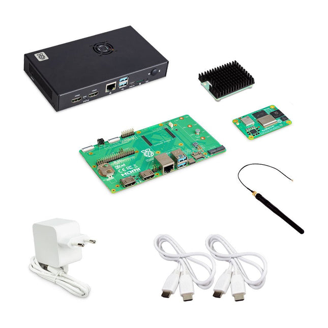
Raspberry Pi Foundation Raspberry Pi Compute Module 5 Development Kit
De Raspberry Pi Compute Module 5 Development Kit biedt een ideaal platform voor het prototypen van ingebedde oplossingen. Deze alles-in-één kit bevat de Compute Module 5, het Compute Module 5 IO Board en alle benodigde accessoires om uw productontwerp te starten. Compute Module 5 (CM5104032) 2,4-GHz quad-core 64-bit Arm Cortex-A76 CPU VideoCore VII GPU, ondersteunt OpenGL ES 3.1 en Vulkan 1.3 4 GB LPDDR4X-4267 SDRAM 32 GB MLC eMMC-geheugen 1x Dual 4Kp60 HDMI-schermuitgang 1x 4Kp60 HEVC-decoder 1x Dual-band 802.11ac wifi en Bluetooth 5.0 2x USB 3.0-interfaces, die gelijktijdige 5 Gbps-werking ondersteunen 1x Gigabit Ethernet, met IEEE 1588-ondersteuning 2x MIPI-camera/display-zendontvangers met 4 rijstroken 1x PCIe 2.0-interface voor snelle randapparatuur 30 GPIO's, die werking op 1,8 V of 3,3 V ondersteunen Randapparatuur: UART, SPI, I²C, I²S, SDIO en PWM Compute Module 5 IO Board 1x Standaard 40-pins GPIO 2x HDMI 2.0 op volledige grootte 2x 4-baans MIPI DSI/CSI-2 FPC (22-pins kabel met een steek van 0,5 mm) 2x USB 3.0 1x Gigabit Ethernet-aansluiting met PoE+ ondersteuning (vereist een aparte Raspberry Pi PoE+ HAT+) 1x M.2 M-key PCIe-socket (voor 2230, 2242, 2260 en 2280 modules) 1x microSD-kaartsleuf (voor gebruik met Lite-modules) 1x RTC-batterijaansluiting 1x 4-pins ventilatorconnector Compute Module 5 IO-behuizing De metalen behuizing transformeert het IO Board in een volledig gesloten computer van industriële kwaliteit. De IO-behuizing is speciaal ontworpen voor de Raspberry Pi Compute Module 5 en beschikt over een ingebouwde ventilator die wordt aangesloten op de 4-pins ventilatorconnector van het IO Board, waardoor verbeterde thermische prestaties worden gegarandeerd. Inbegrepen 1x Raspberry Pi Compute Module 5 (Wireless, 4 GB RAM, 32 GB eMMC) 1x Raspberry Pi Compute Module 5 IO Board (voorgemonteerd geleverd in de IO-behuizing) 1x Raspberry Pi Compute Module 5 IO-behuizing 1x Raspberry Pi Compute Module 5 koeler 1x Raspberry Pi antennekit 1x Raspberry Pi 27 W USB-C PD voeding (EU) 2x Raspberry Pi HDMI naar HDMI-kabels 1x Raspberry Pi USB-A naar USB-C kabel Downloads Datasheet (Compute Module 5) Datasheet (IO Board) Datasheet (IO Case) Datasheet (Cooler) Datasheet (Antenna Kit)
-

Sensepeek Sensepeek 6014 SQ200 (200 MHz handsfree Oscilloscope Probe)
The SQ series of handsfree probes from Sensepeek have a lower point of gravity making them even more stable compared with the original SP series of handsfree probes. All probes in the SQ series are also insulated and can be used handheld as any traditional probe but their full potential is used when measuring handsfree. Features The SQ series of handsfree probes from Sensepeek have a lower point of gravity making them even more stable compared with the original SP series of handsfree probes. All probes in the SQ series are also insulated and can be used handheld as any traditional probe but their full potential is used when measuring handsfree. The SQ series of oscilloscope probes also includes more ground options, have probe tip protection, longer cable and support for oscilloscopes with automatic scaling (10:1). All the loved features of handsfree measurement, exchangeable fine pitch spring tipped test needle, color-coded cable holders and the minimalistic design is maintained to make traditional sized and handheld probes obsolete. Both length and weight of the SQ probes are perfectly balanced to be used with PCBite PCB holders and base plate which is a must for handsfree function. Included 1x SQ200 200 MHz probe with spring tipped test needle 1x SQ probe holder for handsfree measurement 1x Testhook with detachable cables (5 cm & 10 cm) for convenient ground connection 1x Alligator cable for convenient ground connection 1x Standard ground spring, for handheld measurements at rated bandwidth 1x Unique ground spring, for total handsfree measurements at rated bandwidth 1x Set of color coded cable holders (4 colors) 1x Probe tip protection 1x Extra test needle Downloads User Guide SQXX0 Rev1.2
€ 82,52
-
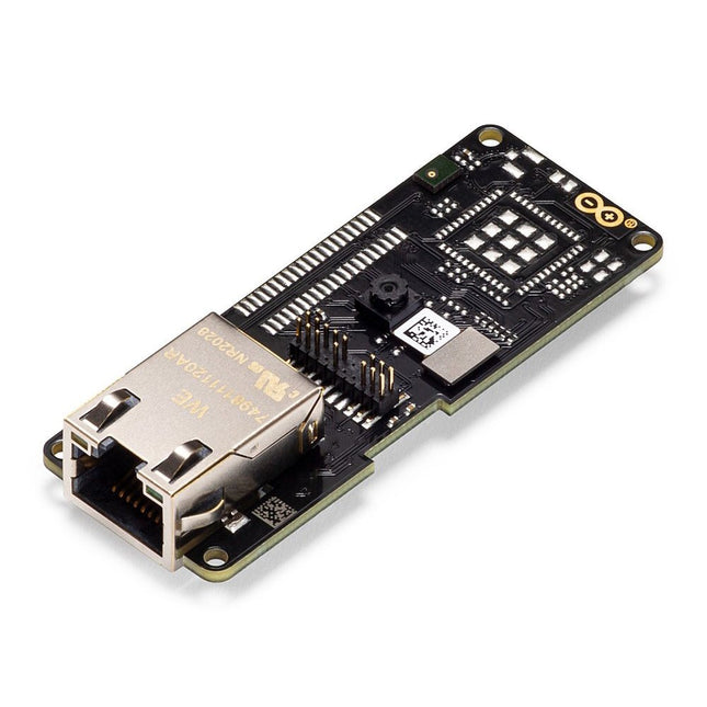
Arduino Arduino Portenta Vision Shield (Ethernet)
Features 324x324 pixels camerasensor: gebruik een van de kernen in Portenta om beeldherkenningsalgoritmes uit te voeren met de OpenMV for Arduino editor 100 Mbps Ethernet connector: verbind uw Portenta H7 met het bekabelde Internet 2 onboard microfoons voor richtingsgevoelige geluidsdetectie: vang en analyseer geluid in real-time JTAG connector: voer low-level debugging uit van uw Portenta bord of speciale firmware updates met behulp van een externe programmer SD-Card aansluiting: sla uw vastgelegde gegevens op de kaart op, of lees configuratiebestanden Het Vision Shield is ontworpen om bovenop de Arduino Portenta familie te passen. De Portenta boards zijn voorzien van multicore 32-bit ARM® Cortex™ processoren die draaien op honderden megahertz, met megabytes aan programmageheugen en RAM. Portenta boards worden geleverd met WiFi en Bluetooth.Embedded computer vision gemakkelijk gemaaktArduino heeft samengewerkt met OpenMV om u een gratis licentie voor de OpenMV IDE aan te bieden, een eenvoudige manier om computervisie te gebruiken met MicroPython als programmeerparadigma. Download de OpenMV voor Arduino Editor van onze professionele tutorials site en blader door de voorbeelden die we voor u hebben voorbereid in de OpenMV IDE. Bedrijven over de hele wereld bouwen al hun commerciële producten op basis van deze eenvoudig-maar-krachtige benadering voor het detecteren, filteren en classificeren van afbeeldingen, QR-codes, en anderen. Debugging met professioneel gereedschapSluit uw Portenta H7 aan op een professionele debugger via de JTAG connector. Gebruik professionele software tools zoals die van Lauterbach of Segger bovenop uw board om uw code stap voor stap te debuggen. Het Vision Shield maakt de benodigde pinnen vrij voor het aansluiten van uw externe JTAG. Camera Himax HM-01B0 cameramodule Resolutie 320 x 320 actieve pixel resolutie met ondersteuning voor QVGA beeldsensor Hoge gevoeligheid 3.6? BrightSense™ pixel technologie Microfoon 2 x MP34DT05 Lengte 66 mm Breedte 25 mm Gewicht 11 gr Voor meer informatie, bekijk de tutorials die door Arduino hier.
€ 69,95€ 19,95
Beste prijs
-
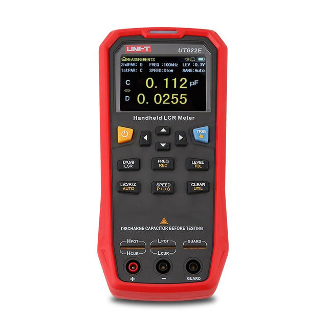
Uni-Trend UNI-T UT622E LCR Meter
The UT622E handheld LCR meter features powerful functions, high accuracy, fast speed, and long standby time. With a clear and intuitive 2.8-inch TFT LCD display, large-capacity rechargeable battery, and 100 kHz test frequency, the meter can be used for longstanding accurate and convenient measurement in any occasion. It is suitable for the measurement and screening of inductance, capacitance, and resistance in laboratories, production lines, maintenance points, etc. Features Max. test frequency: 100 kHz Accuracy: 0.1% Display count: 99999 Max. test rate: 20 times/s DCR: Yes Connectivity: Mini-USB Display: 2.8" TFT LCD Specifications Testfrequency 100 Hz, 120 Hz, 1 kHz, 10 kHz, 100 kHz Test level 0.1 Vmrs, 0.3 Vrms, 1 Vrms Output impedance 100 Ω Measurement parameters Primary: L/C/R/Z/DCRSecondary: D/Q/Θ/ESR DSR speed test Fast (20 times/s), medium (5 times/s), or slow (2 times/s) Range Auto/Hold Tolerance range 1%~20% Equivalent mode Series/Parallel Clearing connection Open/Short circuit Fuse of test ports 0.1 A/250 V Communication interface Mini-USB MAX reading of primary parameters 99999 MIN resolution 0.0001 Maximum accuracy 0.10% L 0.00 µH~99.999 H C 0.00 pF~99.999 mF Z/R 0.0000 Ω~9.9999 MΩ ESR 0.0000 Ω~999.99 Ω D 0.0000~9.9999 Q 0.0000~99999 Θ -179.9°~179.9° DCR 0.01 mΩ~20.000 MΩ Power supply 3.7 V/1800 mAh lithium polymer battery Display 2.8" TFT LCD (320x240) Dimensions 93 x 192 x 44 mm Weight 420 g Included UT622E LCR meter Short circuit board Four-terminal kelvin test leads USB cable Manual Downloads Datasheet Manual Software
€ 325,49
-

Andonstar Andonstar Max Station Upgrade-set voor AD409-modellen
Upgrade je Andonstar AD409, AD409 Pro of AD409 Pro-ES naar het Max-model met deze uitbreidingsset. Het nieuw ontworpen, oversized Max-station biedt voldoende werkruimte, waardoor het perfect is voor grotere projecten en ideaal voor professionele soldeertaken. Inbegrepen 1x Standaard met 2 LED's 1x Reparatiemat 1x Drager 1x Kolom 1x Gereedschapshouder 1x Solderende helpende handen
€ 60,00
-

OWON OWON HDS2202s 2-kanaals oscilloscoop (200 MHz) + multimeter + signaalgenerator
De OWON HDS2202s is een draagbare 3-in-1 multifunctionele tester, die kan worden gebruikt als een 2-kanaals oscilloscoop met een bandbreedte van 200 MHz, en als een multimeter en signaalgenerator. Hij beschikt over een contrastrijk 3,5-inch kleurendisplay dat geschikt is voor onderhoud buitenshuis, snelle metingen ter plaatse, auto-onderhoud, stroomdetectie, enzovoort./p> Kenmerken Oscilloscoop + multimeter + golfvormgenerator, multifunctioneel in één 3,5-inch LCD-kleurenscherm met hoge resolutie en hoog contrast, geschikt voor gebruik buitenshuis 18650 lithium accu, kan 3-6 uur continu werken USB type-C interface, ondersteuning voor powerbank, ondersteuning voor software via een pc Zelfkalibratie functie Ondersteunt SCPI, faciliteert secundary development Specificaties Bandbreedte 200 MHz Kanalen 2-kanaals oscilloscoop + 1-kanaals generator Sample frequentie 1 GSa/s Acquisitie methode Normaal, Piekdetectie Record length 8K Scherm 3,5-inch LCD Golfvorm refresh rate 10.000 wfrms/s Ingangssignaal DC, AC en Aarde Ingangsimpedantie 1 MΩ ±2%, met parallel 16pF ±10pF Dempingswaarden probe 1X,10X,100X,1000X,10000X Maximale ingangsspanning 400 V (DC+AC, PK-PK, 1MΩ ingangsimpedantie) (10:1 demping op de probe) Bandbreedte limiet (typical) 20 MHz Horizontale schaal 2ns/div - 1000s/div, in stappen van 1 - 2 - 5 Verticale gevoeligheid 10mV/div - 10V/div Verticale resolutie 8 bits Triggertype Edge Triggermodi Auto, Normaal, Single Automatische metingen Frequentie, Periode, Amplitude, Max, Min, Gemiddelde, PK-PK Cursormeting ΔV, ΔT, ΔT&ΔV tussen cursors Communicatie interface USB Type-C Multimeter Specificaties Max. resolutie 20.000 counts Testmodus Spanning, Stroom, Weerstand, Capaciteit, Diode en Continuïteitstest Ingangsimpedantie 10 MΩ Maximale ingangsspanning AC 750 V, DC 1000 V Max ingangsstroom DC: 10 A, AC: 10 A Diode 0-2 V Waveform Generator Specificaties Frequentie uitgang Sinus 0,1 Hz - 25 MHz Square 0,1 Hz - 5MHz Ramp 0,1 Hz - 1 MHz Pulse 0,1 Hz - 5 MHz Arbitrary 0,1 Hz - 5 MHz Sample frequentie 125 MSa/s Kanalen 1 kanaal Amplitudebereik (hoge impedantie) 20 mVpp - 5 Vpp Golfvorm Lengte 8K Verticale resolutie 14 bits Uitgangsimpedantie 50 Ω Inbegrepen 1x OWON HDS2202s 1x Voedingsadapter 1x USB-kabel 1x Passieve probe 2x Krokodillenklem kabels 1x Set multimeter probes (een rode en een zwarte) 1x Gebruiksaanwijzing 1x Insteltool voor aanpassing van de probe Downloads Gebruikershandleiding Specificaties SCPI Protocol Quick Guide Software
€ 242,00
-
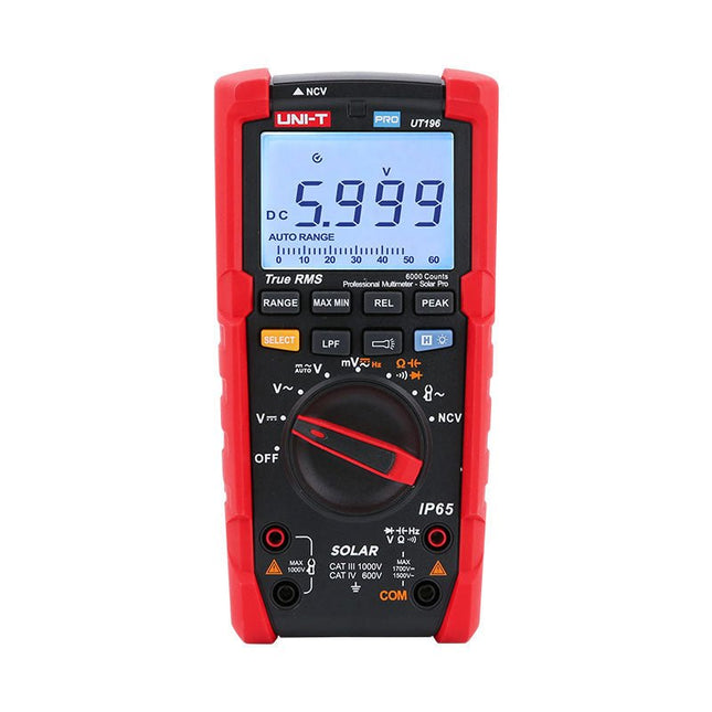
Uni-Trend UNI-T UT196 True RMS Solar Multimeter
De UT196 True RMS Solar multimeter is een ideaal hulpmiddel bij het onderhoud van zonne-energie systemen. Deze robuuste meter is ontworpen voor technici die in weer en wind buiten werken. De UT196 kan spanning meten tot 1700 V DC en 1500 V AC, en stroom tot 3000 A AC met behulp van een externe stroomtangsensor. Deze solar meter is waterdicht conform IP65, en is ook bestand tegen een val van 2 m. De UT196 Solar multimeter is ontworpen met beveiligingen tegen overbelasting van 1700 V DC en 1500 Vrms AC, en getest voor veilig gebruik in CAT III 1000 V en CAT IV 600 V omgevingen. Kenmerken True RMS Meet tot 1700 V DC en 1500 V AC bij hoogspanningstoepassingen zoals zonnepanelen en wind Bescherming conform IP65 CAT III 1000V, CAT IV 600 V Analoge staafgrafiek Frequentiebereik: 45 Hz~1 kHz Laagdoorlaatfilter functie Modus voor lage impedantie Ingebouwde zaklamp, heldere achtergrondverlichting, en visueel alarm Toepassingen Meten van hoge DC-spanningen Uitgangsspanning- en frequentiemeting Spannings- en frequentiemeting Stroom- en frequentiemeting Specificaties Bereik UT196 DC-spanning (V) 1700 V ±0,2% +5 AC-spanning (V) 1500 V ±0,8% +3 Frequentie (Hz) 1 MHz ±0,08% +4 Weerstand (?) 60 M? ±0,8% +2 Capaciteit (F) 60 mF ±1,9% +5 Voeding 9 V batterij Afmetingen 195 x 95 x 58 mm Inbegrepen UT196 Solar multimeter Batterij Meetsnoeren Downloads Datasheet Gebruikershandleiding
€ 129,63


