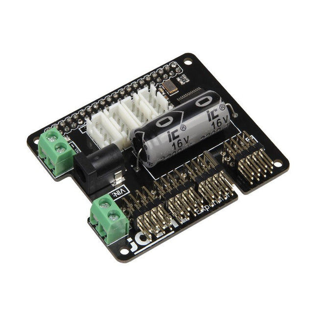
The MotoPi is an extension-board to control and use up to 16 PWM-controlled 5 V servo motors. The board can be additional powered by a voltage between 4.8 V and 6 V so a perfect supply is always guaranteed and even larger projects can be powered. With the additional power supply and the integrated Analog-Digital-Converter, new possibilities can be reached. An additional power supply per motor is not required anymore because all connections (Voltage, Ground, Control) are directly connected to the board. The control and the programing can be directly done, as usual, on the Raspberry Pi. Special features 16 Channels, own clock generator, Inkl. Analog Digital Converter Input 1 Coaxial power connector 5.5 / 2.1 mm, 5 V / 6 A max Input 2 Screw terminal, 4.8-6 V / 6 A max Compatible with Raspberry Pi A+, B+, 2B, 3B Dimensions 65 x 56 x 24 mm Scope of supply Board, manual, fixing material
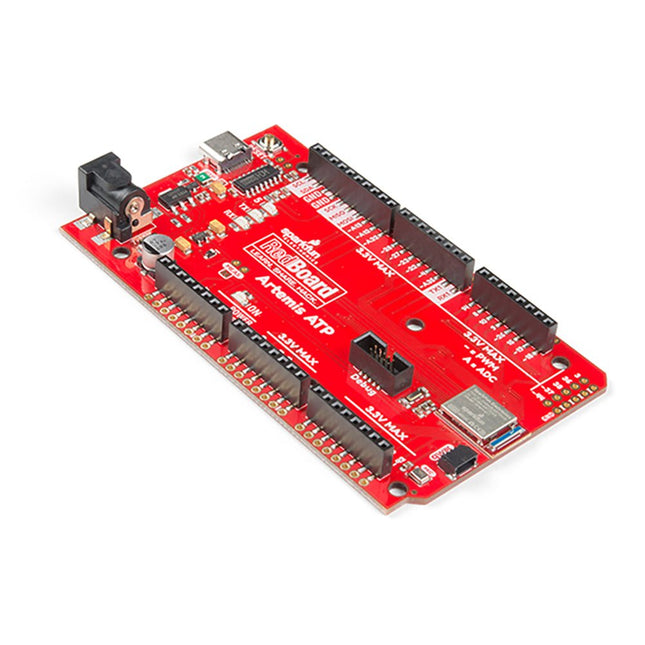
Hoe zit het met de zeefdruk labels? Ze zitten overal. We hebben besloten om de pinnen te labelen zoals ze zijn toegewezen op het Apollo3 IC zelf. Dit maakt het vinden van de pin met de gewenste functie een stuk eenvoudiger. Bekijk de full pin map van de Apollo3 datasheet. Als u echt de 4-bit SPI functionaliteit van de Artemis wilt uitproberen, dan zult u de pinnen 4, 22, 23 en 26 moeten gebruiken. Wilt u de differentiële ADC poort 1 uitproberen? Pinnen 14 en 15. Met de RedBoard Artemis ATP kunt u de indrukwekkende mogelijkheden van de Artemis module uitproberen.De RedBoard Artemis ATP heeft de verbeterde power conditioning en USB naar serieel die we in de loop der jaren hebben verfijnd op onze RedBoard lijn van producten. Een moderne USB-C connector maakt programmeren eenvoudig. Een Qwiic connector maakt I²C eenvoudig. De ATP is volledig compatibel met SparkFun's Arduino kern en kan gemakkelijk geprogrammeerd worden onder de Arduino IDE. We hebben de JTAG connector blootgelegd voor meer gevorderde gebruikers die liever de kracht en snelheid van professionele tools gebruiken. Als u veel GPIO's nodig hebt met een eenvoudig programma, klaar om op de markt te brengen, is de ATP de oplossing die u nodig hebt. We hebben een digitale MEMS microfoon toegevoegd voor mensen die willen experimenteren met always-on spraakcommando's met TensorFlow en machine learning. We hebben zelfs een handige jumper toegevoegd om het stroomverbruik te meten voor testen met laag stroomverbruik.Met 1MB flash en 384k RAM heb je genoeg ruimte voor je schetsen. De Artemis module draait op 48MHz met een 96MHz turbo mode beschikbaar en met Bluetooth om te starten!Kenmerken
Arduino Mega Voetafdruk
1M Flash / 384k RAM
48MHz / 96MHz turbo beschikbaar
6uA/MHz (werkt minder dan 5mW bij volledige werking)
48 GPIO - allen onderbreekbaar
31 PWM kanalen
Ingebouwde BLE radio
10 ADC-kanalen met 14-bits precisie met tot 2,67 miljoen samples per seconde effectieve continue, multi-slot sampling rate
2-kanaals differentiële ADC
2 UART's
6 I²C-bussen
6 SPI-bussen
2/4/8-bit SPI-bus
PDM-interface
I²S-interface
Beveiligde 'Smart Card'-interface
Qwiic-connector
Raspberry Pi 5 provides two four-lane MIPI connectors, each of which can support either a camera or a display. These connectors use the same 22-way, 0.5 mm-pitch “mini” FPC format as the Compute Module Development Kit, and require adapter cables to connect to the 15-way, 1 mm-pitch “standard” format connectors on current Raspbery Pi camera and display products.These mini-to-standard adapter cables for cameras and displays (note that a camera cable should not be used with a display, and vice versa) are available in 200 mm, 300 mm and 500 mm lengths.
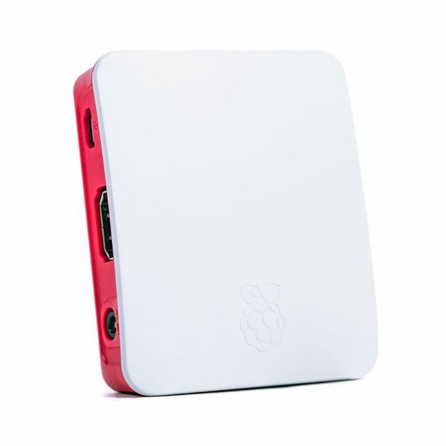
The Raspberry Pi A+ Case has been designed to fit both the Pi 3 Model A+ and the Pi 1 Model A+. The high-quality ABS construction consists of two parts. The base features cut-outs to allow access to the microSD Card and the the HDMI, audio/video and USB ports, as well as the power connector.
Raspberry Pi Pico EVB combined with the WizFi360-PAWizFi360-EVB-Pico is based on Raspberry Pi RP2040 and adds Wi-Fi connectivity using WizFi360. It is pin-compatible with Raspberry Pi Pico board and can be used for IoT Solution development.Specifications
RP2040 microcontroller with 2 MByte Flash
Dual-core cortex M0+ at up to 133 MHz
264 kByte multi-bank high performance SRAM
External Quad-SPI Flash with eXecute In Place (XIP)
Includes WizFi360-PA
Supports Hardwired Internet Protocols: TCP, UDP, WOL over UDP, ICMP, IGMPv1/v2, IPv4, ARP, PPPoE
WiFi 2.4G, 802.11 b/g/n
Support Station / SoftAP / SoftAP+Station operation modes
Support “Data pass-through” and “AT command data transfer” mode
Support serial AT command configuration
Support TCP Server / TCP Client / UDP operating mode
Support configuration of operating channel 0 ~ 13
Support auto 20 MHz / 40 MHz bandwidth
Support WPA_PSK / WPA2_PSK encryption
Support built-in unique MAC address and user configurable
Industrial grade (operating temperature range: -40°C ~ 85°C)
CE, FCC certification
Includes 16 Mbit Flash Memory
Micro-USB B port for power and data (and for reprogramming the Flash)
40 pin 21×51 ‘DIP’ style 1mm thick PCB with 0.1' through-hole pins also with edge castellations
3-pin ARM Serial Wire Debug (SWD) port
Built-in LDO
DownloadsDocumentation
De Power Delivery Board maakt gebruik van een standalone controller om te onderhandelen met de voedingsadapters en overschakelen naar een hogere spanning dan alleen 5V. Zo kan deze voedingsadapter verschillende uitgangsspanningen leveren voor verschillende projecten zodat u niet meerdere voedingsadapters nodig heeft om verschillende output te leveren; het bord kan worden verbonden via SparkFun's Qwiic connect systeem, zodat u niet hoeft te solderen of uit hoeft te zoeken hoe het aangesloten moet zijn.Het SparkFun Power Delivery Board maakt gebruik van de power delivery standaard met behulp van een stand-alone controller van STMicroelectronics, de STUSB4500. De STUSB4500 is een USB power delivery controller die zich richt op stroomverbruiker. Het implementeert een eigen algoritme om met een bron (d.w.z. een wall wart of voedingsadapter) te onderhandelen over het vermogen zonder een externe microcontroller nodig te hebben. U hebt echter wel een microcontroller nodig om het bord te configureren. PDO-profielen worden geconfigureerd in een geïntegreerd niet-vluchtig geheugen. De controller doet al het werk van de vermogensonderhandeling en biedt een eenvoudige manier om te configureren via I2C.Om dit bord te configureren is een I2C bus nodig. Het Qwiic systeem maakt het eenvoudig om het Power Delivery bord aan te sluiten op een microcontroller. Afhankelijk van uw toepassing kunt u ook verbinding maken met de I2C bus via de doorgemetalliseerde SDA en SCL aansluitingen.Eigenschappen
Ingangs- en uitgangsspanningsbereik van 5-20V
Uitgangsstroom tot 5A
Drie configureerbare vermogensafgifteprofielen
Auto-run Type-C™ en USB PD sink-controller
Gecertificeerd USB Type-C™ rev 1.2 en USB PD rev 2.0 (TID #1000133)
Geïntegreerde VBUS-spanningsbewaking
Geïntegreerde VBUS switch gate drivers (PMOS)
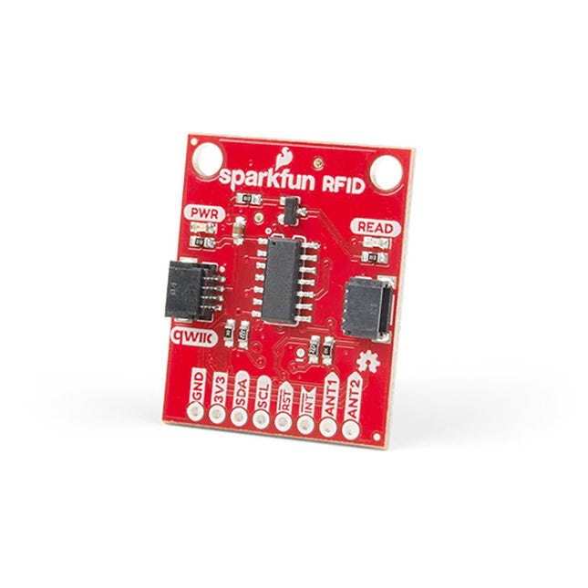
Steek een lezer in de headers, gebruik een Qwiic kabel, scan je 125kHz ID tag, en het unieke 32-bit ID wordt op het scherm getoond. De unit wordt geleverd met een lees LED en buzzer, maar maak je geen zorgen, er is een jumper die je kunt doorknippen om de buzzer uit te schakelen als je dat wilt. Door gebruik te maken van SparkFun's handige Qwiic systeem, is er geen soldeerwerk nodig om het aan te sluiten op de rest van je systeem. We hebben echter nog steeds 0.1'-spaced pinnen als u liever een breadboard gebruikt. Met behulp van de ATtiny84A aan boord, neemt de Qwiic RFID de zes bytes ID tag van je 125kHz RFID kaart, koppelt er een tijdstempel aan, en zet het op een stapel die tot 20 unieke RFID scans per keer kan bevatten. Deze informatie is gemakkelijk te verkrijgen met enkele eenvoudige I²C commando's.
Dit carrier bord combineert een 2.4' TFT scherm, zes adresseerbare LED's, on-board spanningsregelaar, een 6-pins IO-connector, en microSD slot met het M.2 pin connector slot zodat het kan worden gebruikt met compatibele processorborden in ons MicroMod ecosysteem. We hebben dit carrier board ook uitgerust met Atmel's ATtiny84 met 8kb programmeerbare flash. Deze kleine jongen is voorgeprogrammeerd om met de processor te communiceren en via I2C druktoetsen te lezen. Eigenschappen M.2 MicroMod Connector 240 x 320 pixel, 2.4' TFT display 6 Addresseerbare APA102 LEDs Magnetische Buzzer USB-C Connector 3.3 V 1 A spanningsregelaar Qwiic Connector Boot/Reset toetsen RTC Backup Batterij & laadcircuit microSD Kruiskopschroef M2.5 x 3 mm meegeleverd
Maker Line is een lijnsensor met 5 x IR sensoren array die in staat is om lijnen te volgen van 13 mm tot 30 mm breedte.
De sensor calibratie is ook vereenvoudigd. Het is niet nodig om de potentiometer voor elke IR sensor aan te passen. U hoeft alleen maar de calibrate knop gedurende 2 seconden in te drukken om de calibratie modus te openen. Daarna moet u de sensoren over de lijn laten vegen, nogmaals op de knop drukken en u bent klaar om te gaan.
De kalibratiegegevens worden opgeslagen in EEPROM en deze blijven intact, zelfs als de sensor is uitgeschakeld. Kalibratie hoeft dus maar één keer te worden uitgevoerd, tenzij de sensorhoogte, lijnkleur of achtergrondkleur is veranderd.
Maker Line ondersteunt ook dubbele uitgangen: 5 x digitale uitgangen voor de status van elke sensor onafhankelijk, wat vergelijkbaar is met conventionele IR-sensor, maar u krijgt het voordeel van eenvoudige kalibratie, en ook een analoge uitgang, waar de spanning de lijnpositie vertegenwoordigt. De analoge uitgang biedt ook een hogere resolutie in vergelijking met afzonderlijke digitale uitgangen. Dit is vooral nuttig wanneer een hoge nauwkeurigheid vereist is bij het bouwen van een lijnvolgende robot met PID regeling.
Kenmerken
Bedrijfsspanning: DC 3,3 V en 5 V compatibel (met omgekeerde polariteitsbeveiliging)
Aanbevolen lijndikte: 13 mm tot 30 mm
Selecteerbare lijnkleur (licht of donker)
Sensor afstand (hoogte): 4 mm tot 40 mm (Vcc = 5 V, zwarte lijn op wit oppervlak)
Sensor Vernieuwingsfrequentie: 200 Hz
Eenvoudig kalibratieproces
Dubbele uitgangstypen: 5 x digitale uitgangen vertegenwoordigen elke IR-sensor staat, 1 x analoge uitgang vertegenwoordigt lijn positie.
Ondersteunt een breed scala aan controllers, zoals Arduino, Raspberry Pi etc.
Downloads
Datasheet
Tutorial: Een goedkope lijnvolgende robot bouwen
Het Motorino bord is een uitbreidingsbord om tot 16 PWM-gestuurde 5V-Servo-motoren aan te sturen en te gebruiken. De bijgeleverde klokgenerator zorgt voor een zeer nauwkeurig PWM-signaal en een zeer nauwkeurige positionering. Het bord heeft 2 ingangen voor een spanning van 4,8 V tot 6 V die gebruikt kan worden voor maximaal 11 A. Met deze ingang is een perfecte stroomvoorziening altijd gegarandeerd en zijn zelfs grotere projecten geen probleem. De voeding loopt direct over de Motorino die zorgt voor een aansluiting voor spanning, massa en aansturing. Met de ingebouwde condensator wordt de spanning gebufferd wat een plotselinge spanningsval bij een hoge belasting voorkomt. Maar er is ook de mogelijkheid om een andere condensator aan te sluiten. De besturing en het programmeren kan, zoals gebruikelijk, met de Arduino. Handleidingen en code voorbeelden maken een snelle introductie voor beginners mogelijk. Speciale kenmerken 16 Kanalen, eigen klok generator Input 1 Coaxiale voedingsconnector 5,5 / 2,1 mm, 4,8-6 V / 5 A max Input 2 Schroef-terminal, 4,8-6 V / 6 A max Communicatie 16 x PWM Compatibel met Arduino Uno, Mega en wellicht meer microcontroller met Arduino-compatibele pinout Afmetingen 69 x 24 x 56 mm Werkingssfeer Bord, Handleiding, Winkelverpakking
The DiP-Pi Power Master is an Advanced Powering System with embedded sensors interfaces that cover most of possible needs for application based on Raspberry Pi Pico. It can supply the system with up to 1.5 A @ 4.8 V delivered from 6-18 VDC on various powering schemes like Cars, Industrial plant etc., additionally to original micro-USB of the Raspberry Pi Pico. It supports LiPo or Li-Ion Battery with Automatic Charger as also automatic switching from cable powering to battery powering or reverse (UPS functionality) when cable powering lost. Extended Powering Source (EPR) is protected with PPTC Resettable fuse, Reverse Polarity, as also ESD.The DiP-Pi Power Master contains Raspberry Pi Pico embedded RESET button as also ON/OFF Slide Switch that is acting on all powering sources (USB, EPR or Battery). User can monitor (via Raspberry Pi Pico A/D pins) battery level and EPR Level with PICO’s A/D converters. Both A/D inputs are bridged with 0402 resistors (0 OHM) therefore if for any reason user needs to use those Pico pins for their own application can be easy removed. The charger is automatically charging connected battery (if used) but in addition user can switch charger ON/OFF if their application needs it. DiP-Pi Power Master can be used for cable powered systems, but also for pure Battery Powered System with ON/OFF. Each powering source status is indicated by separate informative LEDs (VBUS, VSYS, VEPR, CHGR, V3V3).User can use any capacity of LiPo or Li-Ion type; however, must take care to use PCB protected batteries with max discharge current allowed of 2 A. The embedded battery charger is set to charge battery with 240 mA current. This current is set by resistor so if user need more/less can himself to change it.In Addition to all above features DiP-Pi Power Master is equipped with embedded 1-wire and DHT11/22 sensors interfaces. Combination of the extended powering, battery, and sensors interfaces make the DiP-Pi Power Master ideal for applications like data logger, plants monitoring, refrigerators monitoring etc.DiP-Pi Power Master is supported with plenty of ready to use examples written in Micro Python or C/C++.SpecificationsGeneral
Dimensions 21 x 51 mm
Raspberry Pi Pico pinout compatible
Independent Informative LEDs (VBUS, VSYS, VEPR, CHGR, V3V3)
Raspberry Pi Pico RESET Button
ON/OFF Slide Switch acting on all powering sources (USB, EPR, Battery)
External Powering 6-18 V DC (Cars, Industrial Applications etc.)
External Power (6-18 VDC) Level Monitoring
Battery Level Monitoring
Inverse Polarity Protection
PPTC Fuse Protection
ESD Protection
Automatic Battery Charger (for PCB protected LiPo, Li-Ion – 2 A Max) Automatic/User Control
Automatic Switch from Cable Powering to Battery Powering and reverse (UPS Functionality)
Various powering schemes can be used at the same time with USB Powering, External Powering and Battery Powering
1.5 A @ 4.8 V Buck Converter on EPR
Embedded 3.3 V @ 600mA LDO
Embedded 1-wire Interface
Embedded DHT-11/22 Interface
Powering Options
Raspberry Pi Pico micro-USB (via VBUS)
External Powering 6-18 V (via dedicated Socket – 3.4/1.3 mm)
External Battery
Supported Battery Types
LiPo with protection PCB max current 2A
Li-Ion with protection PCB max current 2A
Embedded Peripherals and Interfaces
Embedded 1-wire interface
Embedded DHT-11/22 Interface
Programmer Interface
Standard Raspberry Pi Pico C/C++
Standard Raspberry Pi Pico Micro Python
Case CompatibilityDiP-Pi Plexi-Cut CaseSystem Monitoring
Battery Level via Raspberry Pi Pico ADC0 (GP26)
EPR Level via Raspberry Pi Pico ADC1 (GP27)
Informative LEDs
VB (VUSB)
VS (VSYS)
VE (VEPR)
CH (VCHR)
V3 (V3V3)
System Protection
Direct Raspberry Pi Pico Hardware Reset Button
ESD Protection on EPR
Reverse Polarity Protection on EPR
PPTC 500 mA @ 18 V fuse on EPR
EPR/LDO Over Temperature protection
EPR/LDO Over Current protection
System Design
Designed and Simulated with PDA Analyzer with one of the most advanced CAD/CAM Tools – Altium Designer
Industrial Originated
PCB Construction
2 ozcopper PCB manufactured for proper high current supply and cooling
6 mils track/6 mils gap technology 2 layers PCB
PCB Surface Finishing – Immersion Gold
Multi-layer Copper Thermal Pipes for increased System Thermal Response and better passive cooling
Downloads
Datasheet
Datasheet
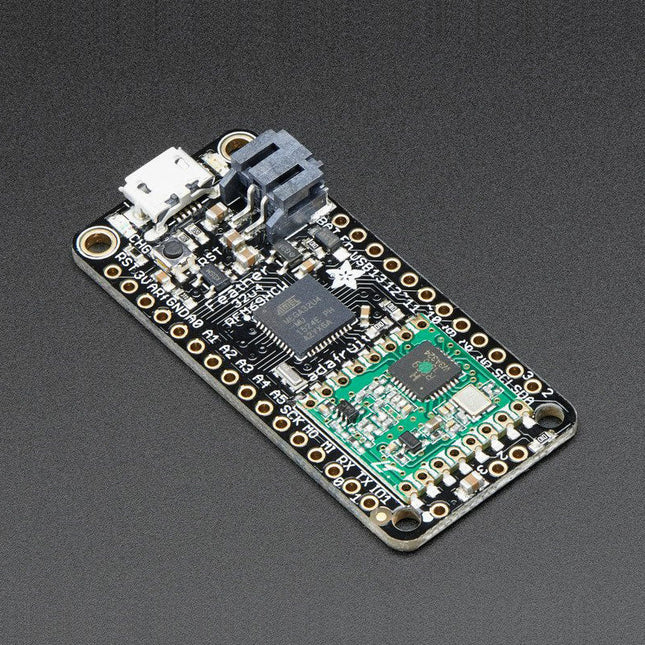
Deze 900 MHz radio-versie kan worden gebruikt voor 868 MHz of 915 MHz transmissie/ontvangst – de exacte radiofrequentie wordt bepaald wanneer u de software laadt omdat deze dynamisch kan worden afgestemd.In het hart van de Feather 32u4 zit een ATmega32u4, geklokt op 8 MHz en op 3,3 V logica. Deze chip heeft 32 K flash en 2 K RAM, met ingebouwde USB, dus niet alleen heeft het een USB-naar-Serieel programma & debug mogelijkheid ingebouwd zonder noodzaak voor een FTDI-achtige chip, het kan ook fungeren als een muis, toetsenbord, USB MIDI-apparaat, enz.Om het gemakkelijk te gebruiken te maken voor draagbare projecten, hebben we een connector toegevoegd voor elke 3.7 V Lithium polymeer batterij en ingebouwd om de batterij op te laden. Je hebt geen batterij nodig, hij werkt prima rechtstreeks vanaf de micro USB connector. Maar als u wel een batterij hebt, kunt u die meenemen op reis en dan de USB aansluiten om op te laden. De Feather schakelt automatisch over op USB-voeding als die beschikbaar is. We hebben ook de batterij via een deler verbonden met een analoge pin, zodat je de batterijspanning kunt meten en monitoren om te detecteren wanneer je moet opladen.Functies
Afmetingen 2.0' x 0.9' x 0.28' (51 x 23 x 8 mm) zonder headers erin gesoldeerd
Licht als een (grote?) veertje - 5,5 gram
ATmega32u4 @ 8 MHz met 3,3 V logica/voeding
3.3 V regulator met 500 mA piekstroomuitgang
USB native ondersteuning, wordt geleverd met USB bootloader en seriële poort debugging
U krijgt ook een heleboel pinnen - 20 GPIO-pinnen
Hardware seriële, hardware I²C, hardware SPI-ondersteuning
7x PWM pinnen
10x analoge ingangen
Ingebouwde 100 mA lipoly lader met oplaadstatus indicator LED
Pin # 13 rode LED voor algemeen knipperen
Voeding/contactpin
4 bevestigingsgaten
Reset-knop
De Feather 32u4 Radio gebruikt de extra ruimte die over is om een RFM69HCW 868/915 MHz radiomodule toe te voegen. Deze radio's zijn niet goed voor het overbrengen van audio of video, maar ze werken wel goed voor het verzenden van kleine datapakketjes als je meer bereik nodig hebt dan 2,4 GHz (BT, BLE, WiFi, ZigBee)
SX1231 gebaseerde module met SPI interface
Packet radio met kant-en-klare Arduino bibliotheken
Gebruikt de licentievrije ISM-band ('Europese ISM' @ 868 MHz of 'Amerikaanse ISM' @ 915 MHz)
+13 tot +20 dBm tot 100 mW uitgangsvermogen (uitgangsvermogen selecteerbaar in software)
50 mA (+13 dBm) tot 150 mA (+20 dBm) stroomverbruik voor transmissies
Bereik van ca. 350 meter, afhankelijk van obstructies, frequentie, antenne en uitgangsvermogen
Meerpuntsnetwerken met individuele knooppuntadressen maken
Geëncrypteerde packet engine met AES-128
Eenvoudige draadantenne of spot voor uFL-connector
Komt volledig geassembleerd en getest, met een USB bootloader waarmee je het snel kunt gebruiken met de Arduino IDE. Er worden ook koppen meegeleverd zodat je hem kan solderen en in een soldeerloos breadboard kan steken. U zult een klein stukje draad moeten knippen en solderen (elke vaste of vaste kern is prima) om uw antenne te maken.Lipoly batterij en USB kabel niet inbegrepen.
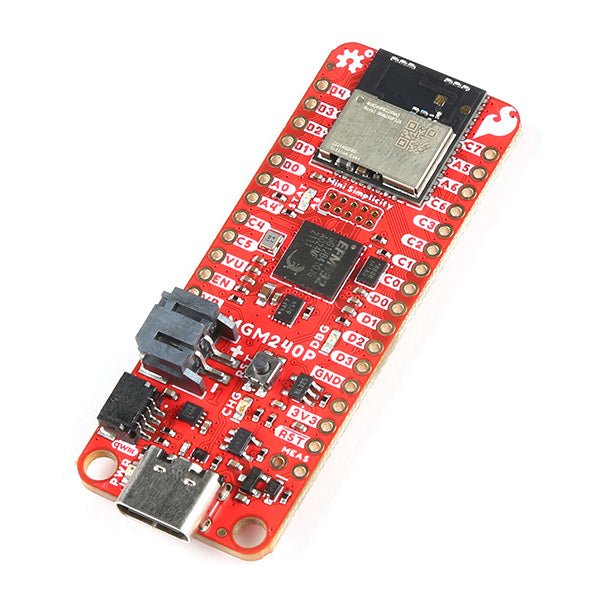
The SparkFun Thing Plus Matter is the first easily accessible board of its kind that combines Matter and SparkFun’s Qwiic ecosystem for agile development and prototyping of Matter-based IoT devices. The MGM240P wireless module from Silicon Labs provides secure connectivity for both 802.15.4 with Mesh communication (Thread) and Bluetooth Low Energy 5.3 protocols. The module comes ready for integration into Silicon Labs' Matter IoT protocol for home automation.
What is Matter? Simply put, Matter allows for consistent operation between smart home devices and IoT platforms without an Internet connection, even from different providers. In doing so, Matter is able to communicate between major IoT ecosystems in order to create a single wireless protocol that is easy, reliable, and secure to use.
The Thing Plus Matter (MGM240P) includes Qwiic and LiPo battery connectors, and multiple GPIO pins capable of complete multiplexing through software. The board also features the MCP73831 single-cell LiPo charger as well as the MAX17048 fuel gauge to charge and monitor a connected battery. Lastly, a µSD card slot for any external memory needs is integrated.
The MGM240P wireless module is built around the EFR32MG24 Wireless SoC with a 32-bit ARM Cortext-M33 core processor running at 39 MHz with 1536 kb Flash memory and 256 kb RAM. The MGM240P works with common 802.15.4 wireless protocols (Matter, ZigBee, and OpenThread) as well as Bluetooth Low Energy 5.3. The MGM240P supports Silicon Labs' Secure Vault for Thread applications.
Specifications
MGM240P Wireless Module
Built around the EFR32MG24 Wireless SoC
32-bit ARM-M33 Core Processor (@ 39 MHz)
1536 kB Flash Memory
256 kB RAM
Supports Multiple 802.15.4 Wireless Protocols (ZigBee and OpenThread)
Bluetooth Low Energy 5.3
Matter-ready
Secure Vault Support
Built-in Antenna
Thing Plus Form-Factor (Feather-compatible):
Dimensions: 5.8 x 2.3 cm (2.30 x 0.9")
2 Mounting Holes:
4-40 screw compatible
21 GPIO PTH Breakouts
All pins have complete multiplexing capability through software
SPI, I²C and UART interfaces mapped by default to labeled pins
13 GPIO (6 labeled as Analog, 7 labeled for GPIO)
All function as either GPIO or Analog
Built-in-Digital to Analog Converter (DAC)
USB-C Connector
2-Pin JST LiPo Battery Connector for a LiPo Battery (not included)
4-Pin JST Qwiic Connector
MC73831 Single-Cell LiPo Charger
Configurable charge rate (500 mA Default, 100 mA Alternate)
MAX17048 Single-Cell LiPo Fuel Gauge
µSD Card Slot
Low Power Consumption (15 µA when MGM240P is in Low Power Mode)
LEDs:
PWR – Red Power LED
CHG – Yellow battery charging status LED
STAT – Blue status LED
Reset Button:
Physical push-button
Reset signal can be tied to A0 to enable use as a peripheral device
Downloads
Schematic
Eagle Files
Board Dimensions
Hookup Guide
Datasheet (MGM240P)
Fritzing Part
Thing+ Comparison Guide
Qwiic Info Page
GitHub Hardware Repo
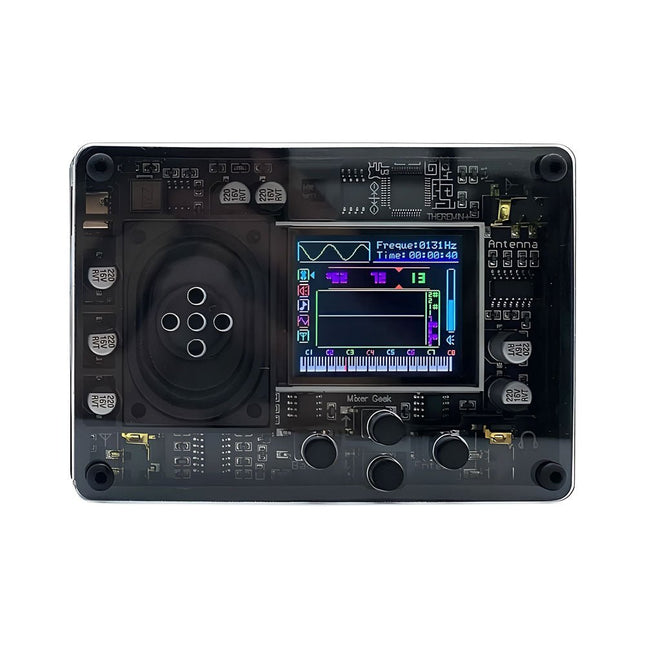
De Mixer Geek Theremin+ is een leuk en innovatief elektronisch muziekinstrument, geïnspireerd op de klassieke theremin. In tegenstelling tot traditionele instrumenten wordt de Theremin+ bespeeld zonder fysiek contact, waarbij de toonhoogte en het volume worden geregeld met handbewegingen in de lucht.
De Theremin+ biedt een spannende en praktische manier om muziek te ontdekken en met geluid te experimenteren.
Kenmerken
Klaar voor gebruik direct uit de doos
Uitgerust met een luidspreker en een kleurenscherm
Intuïtieve navigatie en bevestiging met knoppen
Kies uit meer dan 70 tonen
Meerdere aanpasbare functie-instellingen
Geeft golfvorm, tijd, frequentie, volume en bijbehorende pianotoonhoogte weer (display kan worden uitgeschakeld)
Aangedreven via USB-C poort; compatibel met powerbanks
Compact ontwerp met afneembare telescopische antenne voor eenvoudige opslag
Maakt verbinding met een hoofdtelefoon, externe luidsprekers of opnameapparatuur
Afmetingen: 98 x 70 x 18 mm
Inbegrepen
1x Theremin+ muziekinstrument
2x Antennes
1x USB-C-kabel
Inventor 2040 W is a multi-talented board that does (almost) everything you might want a robot, prop or other mechanical thing to do. Drive a couple of fancy motors with encoders attached? Yep! Add up to six servos? Sure? Attach a little speaker so you can make noise? No problem! It's also got a battery connector so you can power your inventions from AA/AAA or LiPo batteries and carry your miniature automaton/animated top hat/treasure chest that growls at your enemies around with you untethered.You also get a ton of options for hooking up sensors and other gubbins – there's two Qw/ST connectors (and an unpopulated Breakout Garden slot) for attaching breakouts, three ADC pins for analog sensors, photoresistors and such, and three spare digital GPIO you could use for LEDs, buttons or digital sensors. Speaking of LEDs, the board features 12 addressable LEDs (AKA Neopixels) – one for each servo and GPIO/ADC channel.Features
Raspberry Pi Pico W Aboard
Dual Arm Cortex M0+ running at up to 133 Mhz with 264 kB of SRAM
2 MB of QSPI flash supporting XiP
Powered and programmable by USB micro-B
2.4 GHz wireless
2 JST-SH connectors (6 pin) for attaching motors
Dual H-Bridge motor driver (DRV8833)
Per motor current limiting (425 mA)
Per motor direction indicator LEDs
2 pin (Picoblade-compatible) connector for attaching speaker
JST-PH (2 pin) connector for attaching battery (input voltage 2.5-5.5 V)
6 sets of header pins for connecting 3 pin hobby servos
6 sets of header pins for GPIO (3 of which are ADC capable)
12x addressable RGB LEDs/Neopixels
User button
Reset button
2x Qw/ST connectors for attaching breakouts
Unpopulated headers for adding a Breakout Garden slot
Fully assembled
No soldering required (unless you want to add the Breakout Garden slot).
C/C++ and MicroPython libraries
Schematic
Downloads
Download pirate-brand MicroPython
Getting Started with Raspberry Pi Pico
Motor function reference
Servo function reference
MicroPython examples
C++ examples
The EC200U-EU C4-P01 development board features the EC200U-EU LTE Cat 1 wireless communication module, offering a maximum data rate of up to 10 Mbps for downlink and 5 Mbps for uplink. It supports multi-mode and multi-band communication, making it a cost-effective solution.
The board is designed in a compact and unified form factor, compatible with the Quectel multi-mode LTE Standard EC20-CE. It includes an onboard USB-C port, allowing for easy development with just a USB-C cable.
Additionally, the board is equipped with a 40-pin GPIO header that is compatible with most Raspberry Pi HATs.
Kenmerken
Equipped with EC200U-EU LTE Cat 1 wireless communication module, multi-mode & multi-band support
Onboard 40-Pin GPIO header, compatible with most Raspberry Pi HATs
5 LEDs for indicating module operating status
Supports TCP, UDP, PPP, NITZ, PING, FILE, MQTT, NTP, HTTP, HTTPS, SSL, FTP, FTPS, CMUX, MMS protocols, etc.
Supports GNSS positioning (GPS, GLONASS, BDS, Galileo, QZSS)
Onboard Nano SIM card slot and eSIM card slot, dual card single standby
Onboard MIPI connector for connecting MIPI screen and is fully compatible with Raspberry Pi peripherals
Onboard camera connector, supports customized SPI cameras with a maximum of 300,000 pixels
Provides tools such as QPYcom, Thonny IDE plugin, and VSCode plugin, etc. for easy learning and development
Comes with online development resources and manual (example in QuecPython)
Specificaties
Applicable Regions
Europe, Middle East, Africa, Australia, New Zealand, Brazil
LTE-FDD
B1, B3, B5, B7, B8, B20, B28
LTE-TDD
B38, B40, B41
GSM / GPRS / EDGE
GSM: B2, B3, B5, B8
GNSS
GPS, GLONASS, BDS, Galileo, QZSS
Bluetooth
Bluetooth 4.2 (BR/EDR)
Wi-Fi Scan
2.4 GHz 11b (Rx)
CAT 1
LTE-FDD: DL 10 Mbps; UL 5 Mbps
LTE-TDD: DL 8.96 Mbps; UL 3.1 Mbps
GSM / GPRS / EDGE
GSM: DL 85.6 Kbps; UL 85.6 Kbps
USB-C Port
Supports AT commands testing, GNSS positioning, firmware upgrading, etc.
Communication Protocol
TCP, UDP, PPP, NITZ, PING, FILE, MQTT, NTP, HTTP, HTTPS, SSL, FTP, FTPS, CMUX, MMS
SIM Card
Nano SIM and eSIM, dual card single standby
Indicator
P01: Module Pin 1, default as EC200A-XX PWM0
P05: Module Pin 5, NET_MODE indicator
SCK1: SIM1 detection indicator, lights up when SIM1 card is inserted
SCK2: SIM2 detection indicator, lights up when SIM2 card is inserted
PWR: Power indicator
Buttons
PWK: Power ON/OFF
RST: Reset
BOOT: Forcing into firmware burning mode
USB ON/OFF: USB power consumption detection switch
Antenna Connectors
LTE main antenna + DIV / WiFi (scanning only) / Bluetooth antenna + GNSS antenna
Operating Temperature
−30~+75°C
Storage Temperature
−45~+90°C
Downloads
Wiki
Quectel Resources
Na het inschakelen begint de YDLIDAR G4 met het roteren en scannen van de omliggende omgeving. De scanafstand is 16 m, en het apparaat hanteert daarbij een scansnelheid van 9.000 keer per seconde. Hij analyseert zorgvuldig zijn omgeving en kan daarin de kleinste objecten detecteren. Doordat zijn uiterst nauwkeurige borstelloze motor en encoder disc is gemonteerd op lagers draait hij erg soepel, en heeft hij een levensduur van maximaal 500.000 bedrijfsuren. De G4 is een goedkope oplossing voor projecten waarbij obstakeldetectie, obstakelvermijding en/of simultaneous localization and mapping (SLAM) vereist is. Alle YDLIDAR producten zijn ROS ready. Kenmerken 360 graden 2D range scanner Stabiele prestaties, hoge precisie Bereik van 16 m Sterke bescherming tegen interferentie door omgevingslicht Borstelloze motoraandrijving, stabiele prestaties FDA Laser safety standard Class I 360 graden omnidirectioneel scannen, 5-12 Hz adaptive scanning frequentie OptoMagnetic technologie Draadloze datacommunicatie Scansnelheid van 9000 Hz Documentatie ROS drive Ydlidar Downloads Page In de 'Downloads' sectie hieronder vindt u de datasheet en de user and development manuals.
Raspberry Pi 5 provides two four-lane MIPI connectors, each of which can support either a camera or a display. These connectors use the same 22-way, 0.5 mm-pitch “mini” FPC format as the Compute Module Development Kit, and require adapter cables to connect to the 15-way, 1 mm-pitch “standard” format connectors on current Raspbery Pi camera and display products.These mini-to-standard adapter cables for cameras and displays (note that a camera cable should not be used with a display, and vice versa) are available in 200 mm, 300 mm and 500 mm lengths.
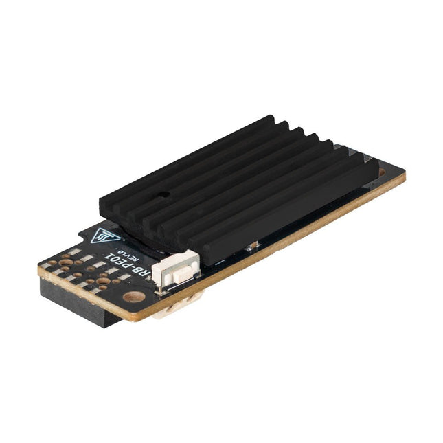
Wide Range Power Supply for Raspberry Pi
With the PiEnergy Mini, you can operate your Raspberry Pi with a voltage of 6 to 36 V DC. You can use the button integrated on the board to both power up and power down your Raspberry Pi.
Communication with the Raspberry Pi is via GPIO4, but this connection can also be cut by removing a resistor to use the pin freely. Thanks to the ultra-flat design, it can also be used in many housings. The pin header is included and not soldered on to keep the design even flatter.
Specifications
Input voltage
6 to 36 V DC
Output voltage
5.1 V
Output current
Up to 3 A (active ventilation recommended for additionally connected loads)
Cable cross-section at the power input
0.2-0.75 mm²
Interface to the Raspberry Pi
GPIO4
Microcontroller
ATtiny5
Further connections
5 V fan connector (2-pin/2.54 mm)Solder pads for external on/off switch
Compatible with
Raspberry Pi 3, 4, 5
Dimensions
23 x 56 x 11 mm
Included
Board with mounted heat sink
Pin header (2x5)
Spacer, screw, nut
Downloads
Datasheet
Manual
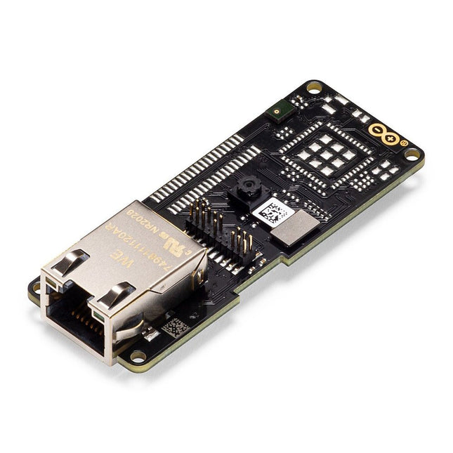
Features
324x324 pixels camerasensor: gebruik een van de kernen in Portenta om beeldherkenningsalgoritmes uit te voeren met de OpenMV for Arduino editor
100 Mbps Ethernet connector: verbind uw Portenta H7 met het bekabelde Internet
2 onboard microfoons voor richtingsgevoelige geluidsdetectie: vang en analyseer geluid in real-time
JTAG connector: voer low-level debugging uit van uw Portenta bord of speciale firmware updates met behulp van een externe programmer
SD-Card aansluiting: sla uw vastgelegde gegevens op de kaart op, of lees configuratiebestanden
Het Vision Shield is ontworpen om bovenop de Arduino Portenta familie te passen. De Portenta boards zijn voorzien van multicore 32-bit ARM® Cortex™ processoren die draaien op honderden megahertz, met megabytes aan programmageheugen en RAM. Portenta boards worden geleverd met WiFi en Bluetooth.Embedded computer vision gemakkelijk gemaaktArduino heeft samengewerkt met OpenMV om u een gratis licentie voor de OpenMV IDE aan te bieden, een eenvoudige manier om computervisie te gebruiken met MicroPython als programmeerparadigma. Download de OpenMV voor Arduino Editor van onze professionele tutorials site en blader door de voorbeelden die we voor u hebben voorbereid in de OpenMV IDE. Bedrijven over de hele wereld bouwen al hun commerciële producten op basis van deze eenvoudig-maar-krachtige benadering voor het detecteren, filteren en classificeren van afbeeldingen, QR-codes, en anderen. Debugging met professioneel gereedschapSluit uw Portenta H7 aan op een professionele debugger via de JTAG connector. Gebruik professionele software tools zoals die van Lauterbach of Segger bovenop uw board om uw code stap voor stap te debuggen. Het Vision Shield maakt de benodigde pinnen vrij voor het aansluiten van uw externe JTAG.
Camera
Himax HM-01B0 cameramodule
Resolutie
320 x 320 actieve pixel resolutie met ondersteuning voor QVGA
beeldsensor
Hoge gevoeligheid 3.6? BrightSense™ pixel technologie
Microfoon
2 x MP34DT05
Lengte
66 mm
Breedte
25 mm
Gewicht
11 gr
Voor meer informatie, bekijk de tutorials die door Arduino hier.
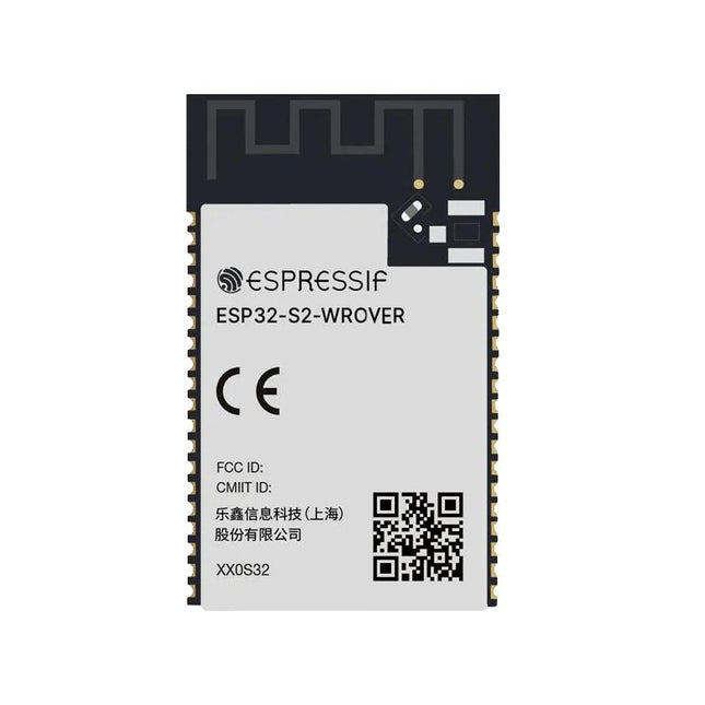
At the core of this module is ESP32-S2, an Xtensa® 32-bit LX7 CPU that operates at up to 240 MHz. The chip has a low-power co-processor that can be used instead of the CPU to save power while performing tasks that do not require much computing power, such as monitoring of peripherals. ESP32-S2 integrates a rich set of peripherals, ranging from SPI, I²S, UART, I²C, LED PWM, TWAITM, LCD, Camera interface, ADC, DAC, touch sensor, temperature sensor, as well as up to 43 GPIOs. It also includes a full-speed USB On-The-Go (OTG) interface to enable USB communication.FeaturesMCU
ESP32-S2 embedded, Xtensa® single-core 32-bit LX7 microprocessor, up to 240 MHz
128 KB ROM
320 KB SRAM
16 KB SRAM in RTC
WiFi
802.11 b/g/n
Bit rate: 802.11n up to 150 Mbps
A-MPDU and A-MSDU aggregation
0.4 µs guard interval support
Center frequency range of operating channel: 2412 ~ 2484 MHz
Hardware
Interfaces: GPIO, SPI, LCD, UART, I²C, I²S, Camera interface, IR, pulse counter, LED PWM, TWAI (compatible with ISO 11898-1), USB OTG 1.1, ADC, DAC, touch sensor, temperature sensor
40 MHz crystal oscillator
4 MB SPI flash
Operating voltage/Power supply: 3.0 ~ 3.6 V
Operating temperature range: –40 ~ 85 °C
Dimensions: 18 × 31 × 3.3 mm
Applications
Generic Low-power IoT Sensor Hub
Generic Low-power IoT Data Loggers
Cameras for Video Streaming
Over-the-top (OTT) Devices
USB Devices
Speech Recognition
Image Recognition
Mesh Network
Home Automation
Smart Home Control Panel
Smart Building
Industrial Automation
Smart Agriculture
Audio Applications
Health Care Applications
Wi-Fi-enabled Toys
Wearable Electronics
Retail & Catering Applications
Smart POS Machines