Raspberry Pi 5 provides two four-lane MIPI connectors, each of which can support either a camera or a display. These connectors use the same 22-way, 0.5 mm-pitch “mini” FPC format as the Compute Module Development Kit, and require adapter cables to connect to the 15-way, 1 mm-pitch “standard” format connectors on current Raspbery Pi camera and display products.These mini-to-standard adapter cables for cameras and displays (note that a camera cable should not be used with a display, and vice versa) are available in 200 mm, 300 mm and 500 mm lengths.
De AD584 4-kanaals spanningsreferentiemodule is ontworpen om stabiele en nauwkeurige referentiespanningen van 2,5 V, 5 V, 7,5 V en 10 V te leveren. Het bevat het AD584 geïntegreerde circuit, bekend om zijn hoge nauwkeurigheid en stabiliteit.
Kenmerken
Meerdere uitgangsspanningen: De module kan vier verschillende referentiespanningen (2,5 V, 5 V, 7,5 V en 10 V) afgeven die toegankelijk zijn via een enkele poort.
Microcontroller-gebaseerde schakeling: Een ingebouwde microcontroller vergemakkelijkt het schakelen tussen de vier spanningsuitgangen, met LED-indicatoren die de actieve selectie weergeven.
Gebruiksvriendelijke bediening: Een enkele knop maakt het mogelijk om eenvoudig door de beschikbare referentiespanningen te bladeren.
Transparante behuizing: De module is omhuld door een transparante behuizing, die bescherming biedt terwijl gebruikers de interne componenten kunnen bekijken.
Voedingsopties: Het kan worden gevoed via een ingebouwde lithiumbatterij (niet meegeleverd) of via een 5 V DC-ingang. Een laadindicator geeft statusupdates tijdens het opladen.
Uitvoerinterface: Uitgerust met 4mm-banaanaansluitingen voor veilige en betrouwbare verbindingen.
Inbegrepen
1x AD584 4-kanaals spanningsreferentiemodule met behuizing
Downloads
Datasheet
Entièrement mise à jour pour le Raspberry Pi 5
Raspberry Pi 5 est un petit ordinateur intelligent, de construction britannique qui regorge de potentiel. Fabriqué à l'aide d'un processeur économe en énergie, le Raspberry Pi est conçu pour vous aider à apprendre le codage, découvrir comment fonctionne un ordinateur et construire vos propres projets uniques et incroyables. Ce guide est conçu pour vous montrer à quel point il est facile de démarrer.
Apprendre à :
Configurez votre Raspberry Pi, installez son système d'exploitation, et commencez à utiliser cet ordinateur entièrement fonctionnel.
Commencez à coder des projets, avec des guides étape par étape utilisant les langages de programmation Scratch 3, Python et MicroPython.
Expérimentez en connectant des composants électroniques, et amusez-vous à créer des projets incroyables.
Nouveauté de la 5ème édition :
Mise à jour pour les derniers ordinateurs Raspberry Pi : Raspberry Pi 5 et Raspberry Pi Zèro 2 W.
Couvre le dernier système d'exploitation Raspberry Pi.
Comprend un nouveau chapitre sur le Raspberry Pi Pico !
Téléchargements
GitHub
Een door een Pico W bestuurde alles-in-één industriële automatiseringscontroller met 2,46 GHz draadloze connectiviteit, diverse relais, en een overvloed aan in- en uitgangen. Hij is compatibel met systemen van 6 V tot 40 V.De Automation 2040 W is een door een Pico W / RP2040 bestuurde bewaking- en automatiseringsboard. Hij bevat alle uitstekende functies van de Automation HAT (relais, analoge kanalen, met spanning gevoede uitgangen, en gebufferde ingangen), maar nu op één compact bordje en met een breder spanningsbereik, zodat je hem met meer apparaten kunt gebruiken. Zeer geschikt voor het aansturen van ventilatoren, pompen, elektromagneten, grote motoren, elektronische sloten of statische LED-verlichting (tot 40 V).Alle kanalen (en de knoppen) hebben een bijbehorende indicatie-LED, zodat je in één oogopslag kunt zien wat er met je setup gebeurt, of waarmee je programma's kunt testen zonder dat er hardware is aangesloten.Kenmerken
De Raspberry Pi Pico W op het board
Dual Arm Cortex M0+ die op maximaal 133 MHz draait met 264 KB SRAM
2 MB QSPI flash die XiP ondersteunt
Gevoed en programmeerbaar via USB Micro-B
2,4 GHz draadloos
3x 12-bits ADC-ingangen tot 40 V
4x digitale ingangen tot 40 V
3x digitale sourcing uitgangen op V+ (voedingsspanning)
4 A maximale continue stroom
2 A max stroom bij 500 Hz PWM
3x relais (NC- en NO-klemmen)
2 A tot 24 V
1 A tot 40 V
3,5 mm schroefklemmen voor het aansluiten van ingangen, uitgangen en externe voeding
2x knopschakelaars met LED-indicatoren
Reset knop
2x Qw/ST connectoren voor het bevestigen van breakouts
M2,5 montage gaten
Volledig geassembleerd
Solderen is niet nodig.
C/C++ en MicroPython libraries
Schema
Lay-out
Voeding
Board is compatibel met 12 V, 24 V en 36 V systemen
Vereist een voeding van 6-40 V
Kan 5 V tot 0,5 A leveren voor toepassingen met een lagere spanning
Downloads
Pirate-brand MicroPython
Aan de slag met de Raspberry Pi Pico
MicroPython voorbeelden
MicroPython functie referentie
C++ voorbeelden
C++ functie referentie
Aan de slag met de Automation 2040 W
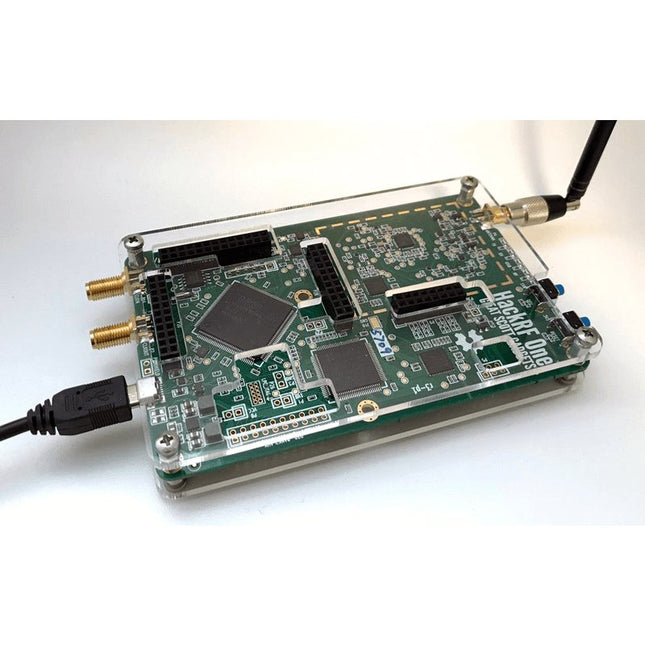
Deze doorzichtige acryl behuizing is de officiële behuizing voor het HackRF One-board. Hij kan de standaard zwarte plastic behuizing van de HackRF One vervangen.
Montage-instructies
Gebruik een plectrum of spudger om de HackRF One printplaat uit de zwarte plastic behuizing te halen.
Steek een lange schroef in elke hoek van het onderste acrylpaneel. Zet elke lange schroef vast met een kort afstandsstuk (5 mm) aan de tegenoverliggende kant van het paneel.
Plaats de HackRF One printplaat (naar boven gericht) bovenop het onderpaneel en steek de uiteinden van de lange schroeven door de bevestigingsgaten in de hoeken van de print.
Zet de printplaat vast met een lang afstandsstuk (6 mm) in elke hoek.
Plaats het bovenste acrylpaneel op de printplaat en lijn de uitsparingen uit met de extension headers op de print.
Zet elke hoek vast met een korte schroef.
Opmerking: Niet te strak aandraaien! Na elke stap alleen met de hand aandraaien.
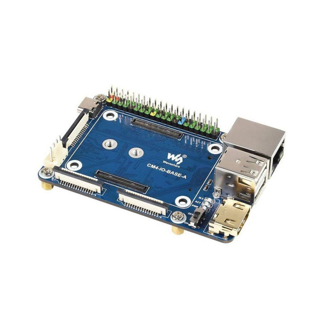
Specifications CM4 socket Suitable for all variants of Compute Module 4 Networking Gigabit Ethernet RJ45 connectorM.2 M KEY, supports communication modules or NVME SSD Connector Raspberry Pi 40-PIN GPIO header USB 2x USB 2.0 Type A2x USB 2.0 via FFC connector Display MIPI DSI display port (15-pin 1.0 mm FPC connector) Camera 2x MIPI CSI-2 camera port (15-pin 1.0 mm FPC connector) Video 2x HDMI port (including one port via FFC connector), supports 4K 30fps output RTC N/A Storage MicroSD card socket for Compute Module 4 Lite (without eMMC) variants Fan header No fan control, 5 V Power input 5 V Dimensions 85 x 56 mm Included 1x CM4-IO-BASE-A 1x SSD mounting screw Downloads Wiki
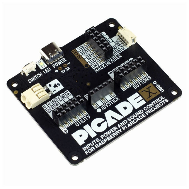
Turn your Raspberry Pi into a retro games console! Picade X HAT includes joystick and button inputs, a 3 W I²S DAC/amplifier, and soft power switch. This HAT has all the same great features as the original Picade HAT but now has no-fuss female Dupont connectors to hook up your joystick and buttons. Simply pop Picade X HAT onto your Pi, plug a USB-C power supply into the connector on the HAT (it back-powers your Pi through the GPIO, so no need for a separate power supply), wire up your controls, and install the driver! It's ideal for your own DIY arcade cabinet builds, or for interfaces that need big, colourful buttons and sound. Features I²S audio DAC with 3 W amplifier (mono) and push-fit terminals Safe power on/off system with tactile power button and LED USB-C connector for power (back-powers your Pi) 4-way digital joystick inputs 6x player button inputs 4x utility button inputs 1x soft power switch input 1x power LED output Plasma button connector Breakout pins for power, I²C, and 2 additional buttons Picade X HAT pinout Compatible with all 40-pin Raspberry Pi models The I²S DAC blends both channels of digital audio from the Raspberry Pi into a single mono output. This is then passed through a 3 W amplifier to power a connected speaker. The board also features a soft power switch that allows you turn your Pi on and off safely without risk of SD card corruption. Tap the connected button to start up, and press and hold it for 3 seconds to fully shutdown and disconnect power. Software/Installation Open a terminal and type curl https://get.pimoroni.com/picadehat | bash to run the installer. You'll need to reboot once the installation is complete, if it doesn't prompt you to do so. The software does not support Raspbian Wheezy Notes With USB-C power connected through Picade X HAT you'll need either to tap the connected power button or the button marked 'switch' on the HAT to power on your Pi.
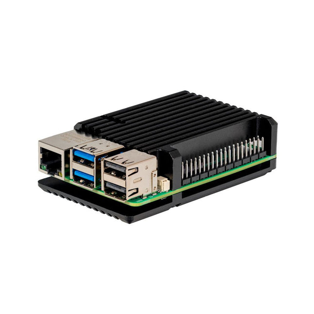
De JOY-iT Armor Case BLOCK is een robuuste aluminium behuizing speciaal ontworpen voor de Raspberry Pi 5. Het biedt uitstekende bescherming tegen hitte en fysieke schokken, waardoor het geschikt is voor uitdagende omgevingen. Het compacte ontwerp zorgt ervoor dat er geen extra ruimte nodig is, waardoor een naadloze integratie in bestaande projecten mogelijk is.
De behuizing is voorzien van een groot koellichaam om de koelefficiëntie te verbeteren. De installatie is eenvoudig, met vier schroeven (meegeleverd) waarmee de behuizing aan de Raspberry Pi wordt bevestigd.
Specificaties
Materiaal
CNC gefreesde aluminiumlegering
Koelprestaties
Inactief: ~39°CVolle belasting: ~75°C
Speciale kenmerken
Groot koellichaam, bescherming tegen schokken en hitte met hetzelfde volume als zonder behuizing
Afmetingen (bovenkant)
69 x 56 x 15,5 mm
Afmetingen (onderzijde)
87 x 56 x 7,5 mm
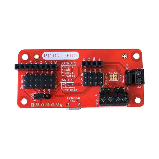
The Picon Zero is an add-on for the Raspberry Pi. It has the same size as a Raspberry Pi Zero, making it ideal to function as a pHat. Of course, it can be used on any other Raspberry Pi via a 40-pin GPIO connector.As well as two full H-Bridge motor drivers, the Picon Zero has several Input/Output pins giving you multiple configuration options. That allows you to easily add outputs or analog inputs to your Raspberry Pi without any complicated software or kernel-specific drivers. At the same time, it opens up 5 GPIO pins from the Raspberry Pi, and it provides the interface for an HC-SR04 ultrasonic distance sensor.The Picon Zero comes with all components, including the headers and screw terminals, fully soldered. Soldering isn't required. You can use it right out of the box.Features
pHat format PCB: 65 mm x 30 mm
Two full H-Bridge motor drivers. Drive up to 1.5 A continuously per channel, at 3 V - 11 V.
Each motor output has both a 2-pin male header and a 2-pin screw terminal.
The motors can be powered from the Picon Zero's 5 V or an external power source (3 V - 11 V).
The Picon Zero's 5 V can be selected to be from the Raspberry Pi's 5 V line, or a USB connector on the Picon Zero. That means that you can effectively have 2 USB battery banks: one to power the servos and motors on the Picon Zero and the other to power the Pi.
4 Inputs that can accept up to 5 V. These inputs can be configured as follows:
Digital inputs
Analog inputs
DS18B20
DHT11
6 Outputs that can drive 5 V and be configured as:
Digital Output
PWM Output
Servo
NeoPixel WS2812
All Inputs and Outputs use GVS 3-pin male headers.
4-pin female header that connects directly to an HC-SR04 ultrasonic distance sensor.
8-pin female header for Ground, 3.3 V, 5 V, and 5 GPIO signals allowing you to add their additional features.
Hardware ConfigurationPicon Zero has two jumpers for setting the hardware configuration. Ensure that you have placed them in the correct position.
JP1 – Board 5 V Selector. This jumper selects where to get the 5 V power from for the Picon Zero Outputs. The options are:
Jumper at the top between RPI and 5 V. The 5 V power for the board is taken from the Raspberry Pi pins on the GPIO connector. Because of the low power output devices and the 5 V motors, all devices can be powered with a single 5 V power input.
Jumper at the bottom between USB and 5 V. The 5 V power is taken from the microUSB connector on the Picon Zero. Useful for higher power output devices, since you can provide extra power through the micro-USB connector on the board
JP2 – Motor Power Selector. This jumper selects where the motors get the power. The two options here are the following:
Jumper at the top between MotorPower and Vin. The motors are driven via the 2-pin screw terminal. The voltage can be between 3 V and 11 V. Useful for motors that require a voltage different from 5 V, or that require more current than is available on either of the USB input connectors
Jumper at the bottom between 5 V and MotorPower. The motors are driven from the board's 5 V.
Raspberry Pi ConfigurationThe Picon Zero is an I²C device. Make sure your Raspberry Pi is set up correctly to use I²C and SMBus:
sudo apt-get install python-smbus python3-smbus python-dev python3-dev
sudo nano /boot/config.txt Add the following lines at the end of the file
dtparam=i2c1=on
dtparam=i2c_arm=on
Press Ctrl-X and use the default prompts to save
sudo reboot
Plugin the Picon Zero onto the Pi and run i2cdetect -y 1If everything goes well, you will see the Picon Zero showing up as address 22 as shown below:
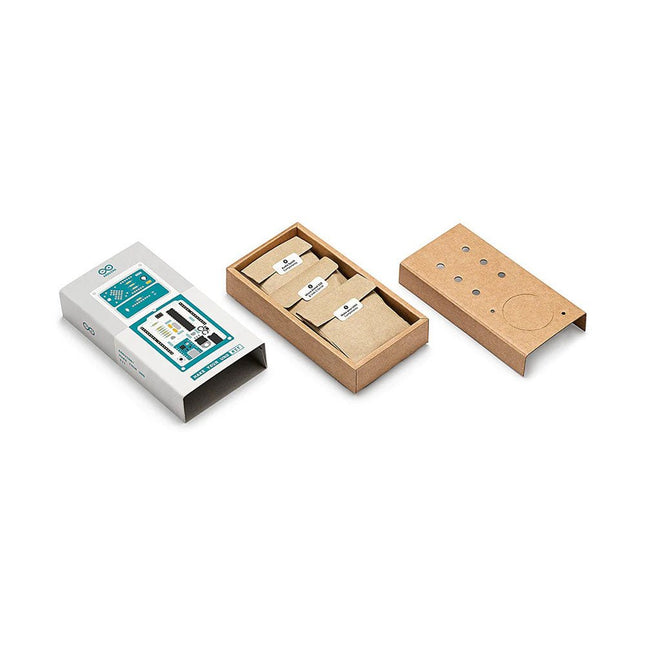
Doe basiskennis van elektronica op door zelf handmatig uw Arduino Uno in elkaar te zetten, raak vertrouwd met solderen door eigenhandig elk onderdeel te monteren, en laat vervolgens uw creativiteit de vrije loop met de enige kit waarmee u ook meteen een synthesizer kan bouwen! De Arduino Make-Your-Uno kit is echt de beste kit om te leren solderen. En als u klaar bent kunt u met deze bundel ook een synthesizer bouwen en muziek maken. Een kit met alle componenten om uw eigen Arduino Uno mét audio synthesizerkaart te bouwen. De Make-Your-Uno kit wordt geleverd met een complete set instructies, beschikbaar op een speciale website. Deze biedt videomateriaal, een interactieve 3D-viewer voor het volgen van gedetailleerde instructies, en hoe u uw board kunt programmeren zodra deze is afgebouwd. Deze kit bevat: Arduino Make-Your-Uno 1x Make-Your-Uno PCB 1x USB C serial adapter board 7x weerstanden 1k Ohm 2x weerstanden 10k Ohm 2x weerstanden 1M Ohm 1x diode (1N4007) 1x 16 MHz kristal 4x gele LED's 1x groene LED 1x drukknop 1x MOSFET 1x LDO (3,3 V) 1x LDO (5 V) 3x keramische condensatoren (22pF) 3x elektrolytische condensatoren (47uF) 7x polyester condensatoren (100nF) 1x socket voor ATMega 328p 2x I/O connectoren 1x connector header 6 pins 1x barrel jack connector 1x ATmega 328p microcontroller Arduino Audio Synth 1x Audio Synth PCB 1x weerstand 100k Ohm 1x weerstand 10 Ohm 1x audio versterker (LM386) 1x keramische condensator (47nF) 1x elektrolytische condensator (47uF) 1x elektrolytische condensator (220uF) 1x polyester condensator (100nF) 4x connectoren pin header 6x potentiometer 10k Ohm met kunststof knoppen Reserveonderdelen 2x elektrolytische condensatoren (47uF) 2x polyester condensatoren (100nF) 2x keramische condensatoren (22pF) 1x drukknop 1x gele LED 1x groene LED Mechanische onderdelen 5x afstandhouders 12 mm 11x afstandhouders 6 mm 5x schroefmoeren 2x schroeven 12 mm
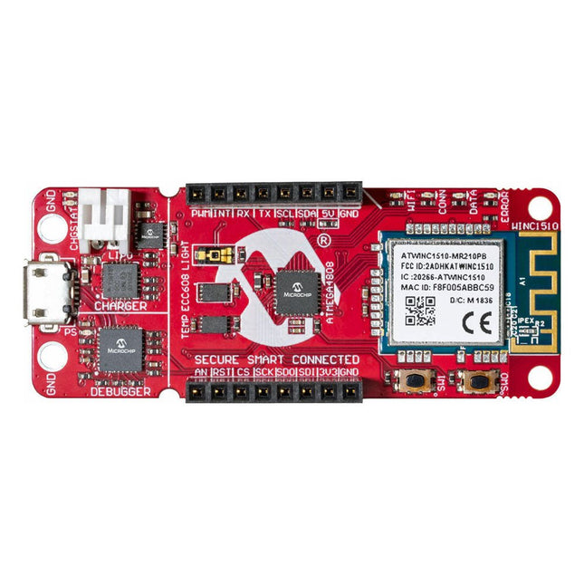
The AVR-IoT WA development board combines a powerful ATmega4808 AVR MCU, an ATECC608A CryptoAuthentication™ secure element IC and the fully certified ATWINC1510 Wi-Fi network controller – which provides the most simple and effective way to connect your embedded application to Amazon Web Services (AWS). The board also includes an on-board debugger, and requires no external hardware to program and debug the MCU.Out of the box, the MCU comes preloaded with a firmware image that enables you to quickly connect and send data to the AWS platform using the on-board temperature and light sensors. Once you are ready to build your own custom design, you can easily generate code using the free software libraries in Atmel START or MPLAB Code Configurator (MCC).The AVR-IoT WA board is supported by two award-winning Integrated Development Environments (IDEs) – Atmel Studio and Microchip MPLAB X IDE – giving you the freedom to innovate with your environment of choice.Features
ATmega4808 microcontroller
Four user LED’s
Two mechanical buttons
mikroBUS header footprint
TEMT6000 Light sensor
MCP9808 Temperature sensor
ATECC608A CryptoAuthentication™ device
WINC1510 WiFi Module
On-board Debugger
Auto-ID for board identification in Atmel Studio and Microchip MPLAB X
One green board power and status LED
Programming and debugging
Virtual COM port (CDC)
Two DGI GPIO lines
USB and battery powered
Integrated Li-Ion/LiPo battery charger
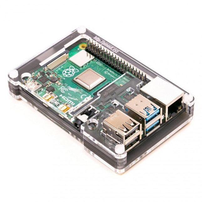
Features Compatible with Raspberry Pi 4 only
Cutout in lid for 40x30mm heatsink or Fan SHIM
Super-slimline profile Fully HAT-compatible Protects your beloved Pi Clear top and base leave Raspberry Pi 4 visible GPIO cut-out Handy laser-etched port labels Leaves all ports accessible Made from lightweight, high-quality, cast acrylic Great for hacking and tinkering! Made in Sheffield, UK Weighing just over 50 grams, the case is lightweight and ideal for mounting to any surface. No tools are required for assembly or disassembly. The dimensions are: 99 × 66 × 15 mm. In the video below you can see a quick assembly guide.
Deze module bevat een geïntegreerde trace-antenne, is FCC-goedgekeurd en bevat alle ontkoppeling en timing mechanismen die anders voor een nRF52840 ontwerp vereist zouden zijn. De Bluetooth-zendontvanger op de nRF52840 is voorzien van een BT 5.1-stack. Het ondersteunt Bluetooth 5, Bluetooth mesh, IEEE 802.15.4 (Zigbee & Thread) en 2.4Ghz RF draadloze protocollen (inclusief Nordic's eigen RF-protocol), zodat u kunt kiezen welke optie het beste past bij uw applicatie. Eigenschappen ARM Cortex-M4 CPU met een floating-point unit (FPU) 1MB interne Flash 256kB intern RAM Geïntegreerde 2.4GHz radio met ondersteuning voor: Bluetooth Low Energy (BLE) -- Met ondersteuning van perifere en/of centrale BLE-apparaten Bluetooth 5 -- Mesh Bluetooth! ANT -- Als u het toestel wilt veranderen in een hartslag- of trainingsmonitor. Nordic's proprietary RF protocol --- Voor als u veilig wilt communiceren met andere Nordic apparaten. Elke I/O peripheral die u nodig kunt hebben. USB -- Maak van uw nRF52840 een USB-apparaat voor massaopslag, gebruik een CDC-interface (seriële USB), en meer. UART -- Serial interfaces met ondersteuning voor hardware flow-control indien gewenst. I2C -- Ieders favoriete 2-draads bi-directionele bus interface SPI -- Als u de voorkeur geeft aan de 3+-draads serial interface Analogue-to-digital converters (ADC) -- Acht pinnen op de nRF52840 Mini Breakout ondersteunen analoge ingangen PWM -- Timer-ondersteuning op elke pin, PWM-ondersteuning voor het aansturen van LED's of servomotoren. Zeer nauwkeurige Real-time clock (RTC) -- ondersteunt ook timed deep-sleep functies. Drie UARTs Primair verbonden met USB-interface. Twee hardware UART's. Twee I2C-bussen Twee SPI-bussen Secundaire SPI-bus, hoofdzakelijk gebruikt voor Flash IC. PDM Audio Processing 2 x analoge Inputs 2 x PWM output 11 x GPIO
Het Data Logging Carrier Board bevat aansluitingen voor I2C via een Qwiic connector of standaard 0.1' doorgemetalliseerde pinnen, samen met SPI en seriële UART aansluitingen voor het loggen van data van randapparatuur die gebruik maakt van deze communicatie protocollen. Met het Data Logging Carrier Board kunt u de voeding schakelen van zowel de Qwiic-connector op het bord als een speciale 3,3V voedingsrail voor niet-Qwiic-randapparatuur, zodat u kunt kiezen wanneer u de randapparatuur waarvan u de gegevens verzamelt, van stroom voorziet. Het bevat ook een oplaadcircuit voor lithium-ion batterijen met één cel en een apart batterijcircuit om een real-time klok op uw processorbord van stroom te voorzien. Eigenschappen M.2 MicroMod Connector microSD socket USB-C Connector 3.3 V 1 A spanningsreglaar Qwiic Connector Boot/Reset toetsen RTC backup-batterij & laadcircuit Onafhankelijke 3.3V spanningsregelaars voor Qwiic bus andere periferie Digitale uitgang van het processorbord schakelt de sluimerstand M2.5 x 3 mm met kruiskopschroef meegeleverd
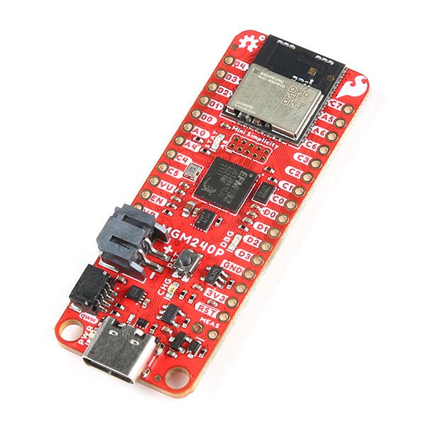
The SparkFun Thing Plus Matter is the first easily accessible board of its kind that combines Matter and SparkFun’s Qwiic ecosystem for agile development and prototyping of Matter-based IoT devices. The MGM240P wireless module from Silicon Labs provides secure connectivity for both 802.15.4 with Mesh communication (Thread) and Bluetooth Low Energy 5.3 protocols. The module comes ready for integration into Silicon Labs' Matter IoT protocol for home automation.
What is Matter? Simply put, Matter allows for consistent operation between smart home devices and IoT platforms without an Internet connection, even from different providers. In doing so, Matter is able to communicate between major IoT ecosystems in order to create a single wireless protocol that is easy, reliable, and secure to use.
The Thing Plus Matter (MGM240P) includes Qwiic and LiPo battery connectors, and multiple GPIO pins capable of complete multiplexing through software. The board also features the MCP73831 single-cell LiPo charger as well as the MAX17048 fuel gauge to charge and monitor a connected battery. Lastly, a µSD card slot for any external memory needs is integrated.
The MGM240P wireless module is built around the EFR32MG24 Wireless SoC with a 32-bit ARM Cortext-M33 core processor running at 39 MHz with 1536 kb Flash memory and 256 kb RAM. The MGM240P works with common 802.15.4 wireless protocols (Matter, ZigBee, and OpenThread) as well as Bluetooth Low Energy 5.3. The MGM240P supports Silicon Labs' Secure Vault for Thread applications.
Specifications
MGM240P Wireless Module
Built around the EFR32MG24 Wireless SoC
32-bit ARM-M33 Core Processor (@ 39 MHz)
1536 kB Flash Memory
256 kB RAM
Supports Multiple 802.15.4 Wireless Protocols (ZigBee and OpenThread)
Bluetooth Low Energy 5.3
Matter-ready
Secure Vault Support
Built-in Antenna
Thing Plus Form-Factor (Feather-compatible):
Dimensions: 5.8 x 2.3 cm (2.30 x 0.9")
2 Mounting Holes:
4-40 screw compatible
21 GPIO PTH Breakouts
All pins have complete multiplexing capability through software
SPI, I²C and UART interfaces mapped by default to labeled pins
13 GPIO (6 labeled as Analog, 7 labeled for GPIO)
All function as either GPIO or Analog
Built-in-Digital to Analog Converter (DAC)
USB-C Connector
2-Pin JST LiPo Battery Connector for a LiPo Battery (not included)
4-Pin JST Qwiic Connector
MC73831 Single-Cell LiPo Charger
Configurable charge rate (500 mA Default, 100 mA Alternate)
MAX17048 Single-Cell LiPo Fuel Gauge
µSD Card Slot
Low Power Consumption (15 µA when MGM240P is in Low Power Mode)
LEDs:
PWR – Red Power LED
CHG – Yellow battery charging status LED
STAT – Blue status LED
Reset Button:
Physical push-button
Reset signal can be tied to A0 to enable use as a peripheral device
Downloads
Schematic
Eagle Files
Board Dimensions
Hookup Guide
Datasheet (MGM240P)
Fritzing Part
Thing+ Comparison Guide
Qwiic Info Page
GitHub Hardware Repo
The FRDM-MCXN947 is a compact and versatile development board designed for rapid prototyping with MCX N94 and N54 microcontrollers. It features industry-standard headers for easy access to the MCU's I/Os, integrated open-standard serial interfaces, external flash memory, and an onboard MCU-Link debugger.
Specificaties
Microcontroller
MCX-N947 Dual Arm Cortex-M33 cores @ 150 MHz each with optimized performance efficiency, up to 2 MB dual-bank flash with optional full ECC RAM, External flash
Accelerators: Neural Processing Unit, PowerQuad, Smart DMA, etc.
Memory Expansion
*DNP Micro SD card socket
Connectivity
Ethernet Phy and connector
HS USB-C connectors
SPI/I²C/UART connector (PMOD/mikroBUS, DNP)
WiFi connector (PMOD/mikroBUS, DNP)
CAN-FD transceiver
Debug
On-board MCU-Link debugger with CMSIS-DAP
JTAG/SWD connector
Sensor
P3T1755 I³C/I²C Temp Sensor, Touch Pad
Expansion Options
Arduino Header (with FRDM expansion rows)
FRDM Header
FlexIO/LCD Header
SmartDMA/Camera Header
Pmod *DNP
mikroBUS
User Interface
RGB user LED, plus Reset, ISP, Wakeup buttons
Inbegrepen
1x FRDM-MCXN947 Development Board
1x USB-C Cable
1x Quick Start Guide
Downloads
Datasheet
Block diagram
Raspberry Pi 5 provides two four-lane MIPI connectors, each of which can support either a camera or a display. These connectors use the same 22-way, 0.5 mm-pitch “mini” FPC format as the Compute Module Development Kit, and require adapter cables to connect to the 15-way, 1 mm-pitch “standard” format connectors on current Raspbery Pi camera and display products.These mini-to-standard adapter cables for cameras and displays (note that a camera cable should not be used with a display, and vice versa) are available in 200 mm, 300 mm and 500 mm lengths.
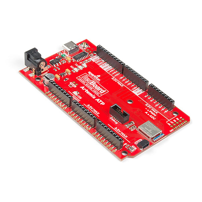
Hoe zit het met de zeefdruk labels? Ze zitten overal. We hebben besloten om de pinnen te labelen zoals ze zijn toegewezen op het Apollo3 IC zelf. Dit maakt het vinden van de pin met de gewenste functie een stuk eenvoudiger. Bekijk de full pin map van de Apollo3 datasheet. Als u echt de 4-bit SPI functionaliteit van de Artemis wilt uitproberen, dan zult u de pinnen 4, 22, 23 en 26 moeten gebruiken. Wilt u de differentiële ADC poort 1 uitproberen? Pinnen 14 en 15. Met de RedBoard Artemis ATP kunt u de indrukwekkende mogelijkheden van de Artemis module uitproberen.De RedBoard Artemis ATP heeft de verbeterde power conditioning en USB naar serieel die we in de loop der jaren hebben verfijnd op onze RedBoard lijn van producten. Een moderne USB-C connector maakt programmeren eenvoudig. Een Qwiic connector maakt I²C eenvoudig. De ATP is volledig compatibel met SparkFun's Arduino kern en kan gemakkelijk geprogrammeerd worden onder de Arduino IDE. We hebben de JTAG connector blootgelegd voor meer gevorderde gebruikers die liever de kracht en snelheid van professionele tools gebruiken. Als u veel GPIO's nodig hebt met een eenvoudig programma, klaar om op de markt te brengen, is de ATP de oplossing die u nodig hebt. We hebben een digitale MEMS microfoon toegevoegd voor mensen die willen experimenteren met always-on spraakcommando's met TensorFlow en machine learning. We hebben zelfs een handige jumper toegevoegd om het stroomverbruik te meten voor testen met laag stroomverbruik.Met 1MB flash en 384k RAM heb je genoeg ruimte voor je schetsen. De Artemis module draait op 48MHz met een 96MHz turbo mode beschikbaar en met Bluetooth om te starten!Kenmerken
Arduino Mega Voetafdruk
1M Flash / 384k RAM
48MHz / 96MHz turbo beschikbaar
6uA/MHz (werkt minder dan 5mW bij volledige werking)
48 GPIO - allen onderbreekbaar
31 PWM kanalen
Ingebouwde BLE radio
10 ADC-kanalen met 14-bits precisie met tot 2,67 miljoen samples per seconde effectieve continue, multi-slot sampling rate
2-kanaals differentiële ADC
2 UART's
6 I²C-bussen
6 SPI-bussen
2/4/8-bit SPI-bus
PDM-interface
I²S-interface
Beveiligde 'Smart Card'-interface
Qwiic-connector
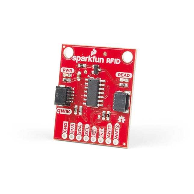
Steek een lezer in de headers, gebruik een Qwiic kabel, scan je 125kHz ID tag, en het unieke 32-bit ID wordt op het scherm getoond. De unit wordt geleverd met een lees LED en buzzer, maar maak je geen zorgen, er is een jumper die je kunt doorknippen om de buzzer uit te schakelen als je dat wilt. Door gebruik te maken van SparkFun's handige Qwiic systeem, is er geen soldeerwerk nodig om het aan te sluiten op de rest van je systeem. We hebben echter nog steeds 0.1'-spaced pinnen als u liever een breadboard gebruikt. Met behulp van de ATtiny84A aan boord, neemt de Qwiic RFID de zes bytes ID tag van je 125kHz RFID kaart, koppelt er een tijdstempel aan, en zet het op een stapel die tot 20 unieke RFID scans per keer kan bevatten. Deze informatie is gemakkelijk te verkrijgen met enkele eenvoudige I²C commando's.
The Raspberry Pi A+ Case has been designed to fit both the Pi 3 Model A+ and the Pi 1 Model A+. The high-quality ABS construction consists of two parts. The base features cut-outs to allow access to the microSD Card and the the HDMI, audio/video and USB ports, as well as the power connector.
Raspberry Pi Pico EVB combined with the WizFi360-PAWizFi360-EVB-Pico is based on Raspberry Pi RP2040 and adds Wi-Fi connectivity using WizFi360. It is pin-compatible with Raspberry Pi Pico board and can be used for IoT Solution development.Specifications
RP2040 microcontroller with 2 MByte Flash
Dual-core cortex M0+ at up to 133 MHz
264 kByte multi-bank high performance SRAM
External Quad-SPI Flash with eXecute In Place (XIP)
Includes WizFi360-PA
Supports Hardwired Internet Protocols: TCP, UDP, WOL over UDP, ICMP, IGMPv1/v2, IPv4, ARP, PPPoE
WiFi 2.4G, 802.11 b/g/n
Support Station / SoftAP / SoftAP+Station operation modes
Support “Data pass-through” and “AT command data transfer” mode
Support serial AT command configuration
Support TCP Server / TCP Client / UDP operating mode
Support configuration of operating channel 0 ~ 13
Support auto 20 MHz / 40 MHz bandwidth
Support WPA_PSK / WPA2_PSK encryption
Support built-in unique MAC address and user configurable
Industrial grade (operating temperature range: -40°C ~ 85°C)
CE, FCC certification
Includes 16 Mbit Flash Memory
Micro-USB B port for power and data (and for reprogramming the Flash)
40 pin 21×51 ‘DIP’ style 1mm thick PCB with 0.1' through-hole pins also with edge castellations
3-pin ARM Serial Wire Debug (SWD) port
Built-in LDO
DownloadsDocumentation
De SparkFun RP2350 Pro Micro biedt een krachtig ontwikkelingsplatform, gebouwd rond de RP2350-microcontroller. Dit bord maakt gebruik van de bijgewerkte Pro Micro-vormfactor. Het bevat een USB-C-connector, Qwiic-connector, WS2812B adresseerbare RGB-LED, opstart- en resetknoppen, opnieuw instelbare PTC-zekering en PTH- en gekartelde soldeerpads.
De RP2350 is een unieke dual-core microcontroller met twee ARM Cortex-M33-processors en twee Hazard3 RISC-V-processors, allemaal draaiend op maximaal 150 MHz! Dit betekent niet dat de RP2350 een quad-core microcontroller is. In plaats daarvan kunnen gebruikers selecteren welke twee processors tijdens het opstarten moeten worden uitgevoerd. U kunt twee processors van hetzelfde type of één van elk gebruiken. De RP2350 beschikt ook over 520 kB SRAM in tien banken, een groot aantal randapparatuur, waaronder twee UART's, twee SPI- en twee I²C-controllers, en een USB 1.1-controller voor host- en apparaatondersteuning.
De Pro Micro bevat ook twee uitgebreide geheugenopties: 16 MB externe Flash en 8 MB PSRAM aangesloten op de QSPI-controller van de RP2350. De RP2350 Pro Micro werkt met C/C++ met behulp van de Pico SDK-, MicroPython- en Arduino-ontwikkelomgevingen.
Kenmerken
RP2350-microcontroller
8 MB PSRAM
16 MB Flash
Voedingsspanning
USB: 5 V
RAW: 5,3 V (max.)
Pro Micro Pinout
2x UART
1x SPI
10x GPIO (4 gebruikt voor UART1 en UART0)
4x analoog
USB-C-connector
USB 1.1 host-/apparaatondersteuning
Qwiic-connector
Knoppen
Reset
Boot
LED's
WS2812 Adresseerbare RGB-LED
Rode voedings-LED
Afmetingen: 33 x 17,8 mm
Downloads
Schematic
Eagle Files
Board Dimensions
Hookup Guide
RP2350 MicroPython Firmware (Beta 04)
SparkFun Pico SDK Library
Arduino Pico Arduino Core
Datasheet (RP2350)
Datasheet (APS6404L PSRAM)
RP2350 Product Brief
Raspberry Pi RP2350 Microcontroller Documentation
Qwiic Info Page
GitHub Repository