Designing, Wiring, and Controlling
Build Your Own Coffee Roaster is a practical guide to constructing and operating the Cobra Smart Roaster and its companion Open Roaster Controller (ORC).
The e-book walks the reader through every stage of the build, from assembling the powerhead and wiring the system to installing and configuring the controller. Along the way, you’ll learn how to use the Raspberry Pi to bring precision and flexibility to your roasting process.
Clear, step-by-step chapters cover:
Powerhead construction and required components
Low- and high-voltage wiring
Installing the ORC, network setup, and using the web interface
Roasting coffee with the Cobra in different setups, including hand-stir and bread-machine roasting
Advanced topics such as manual mode, fixed profiles, Artisan-Scope connections, and ORC system programming
A complete parts list, practical guidance throughout, and concise explanations make this e-book a useful reference for anyone interested in building, modifying, or understanding their own coffee-roasting system.
Le téléchargement intégral de ce numéro est disponible pour nos membres GOLD et GREEN sur le site Elektor Magazine !
Pas encore membre ? Cliquez ici.
Relio v1.0 – détection de présence et contrôle à distanceUn contrôleur intelligent pour appareils électriques compatible Matter
concevoir de meilleurs circuits imprimésUn guide pratique pour les professionnels et les makers
KiCad 9Nouvelles fonctionnalités et mises à jour
picoampèremètre de précision (1)Traceur de courbes jusqu’à la gamme des pA !
étoile de Noël 2025Fabriquer votre étoile
testeur de continuité 100 mV
l’innovation électronique en EuropeLes entreprises à suivre de près
productronica 2025 : quoi de neuf dans le développement et la production électroniques
l’automatisation face aux défis de la relocalisation, des tarifs et de la pénurie de main-d’œuvre
Au-delà de la résilienceLa circularité dans l’électronique
composants passifsBobines à faibles pertes pour convertisseurs CC/CC à haut rendement
comment les machines de bureau démocratisent la production de circuits imprimés
démarrer en électronique......Alimentation
sur le vifButton Fever
soudage : quoi de neuf en 2025 ?Conseils pratiques en direct depuis l’établi
SimulIDEUn outil tout-en-un pour le prototypage de circuits
2025 : une odyssée de l’IADe l’autocomplétion à un véritable collègue
Wordy Christmas TreeUn sapin électronique polyglotte pour les fêtes
projet 2.0Corrections, mises à jour et courrier des lecteurs
Analog Pipeline DistortionUn effet audio original pour guitares et autres instruments
carte émetteur-récepteur audio ESP32 (3)Transmission stéréo et double radio
Le téléchargement intégral de ce numéro est disponible pour nos membres GOLD et GREEN sur le site Elektor Magazine !
Pas encore membre ? Cliquez ici.
adaptateur de mesure USBTest du courant et des signaux des ports USB
sortie boucle de courant 4-20 mA pour Arduino UnoUne interface de boucle de courant fiable et insensible aux interférences électromagnétiques
commande automatique pour aspirateurGardez votre établi propre
générateur DDS avec ATtiny
testeur d'ampli-op V2Nouveau circuit imprimé – désormais compatible avec les CMS
amplificateur audio à tube 550 mWson chaleureux des tubes à vide
surveillance des fusiblesavec une LED clignotante
préamplificateur RIAA HQExploitez tout le potentiel sonore de vos disques vinyles !
Outil de réglage pour platines vinylesGénérateur de lumière stroboscopique 100–120 Hz basé sur Arduino
Elektor Classics : ampli vidéo
gradateur à télécommande infrarougeContrôlez votre éclairage avec confort et précision
comment utiliser switch…case avec des chaînes de caractères en C++/EDI Arduino
détecteur d’aimantsAvec un simple capteur à effet Hall
bouton de mise sous tension intelligent pour Raspberry PiUne solution pour Raspberry Pi jusqu’au modèle 4
astuces clés pour makersDes conseils pros pour vos projets
projets pratiques avec le timer 555Commande de moteur CC et jeux de rapidité
moniteur de charge CA simpleÉconomisez de l'énergie grâce à un appareil simple
batteries externes en parallèleTrois jours d’autonomie
VFO jusqu’à 15 MHzRéalisation avec un Raspberry Pi Pico
accordeur de violon avec ATtiny202
Elektor Classics : ampli vidéo pour TV N&B
capacimètre20 pF à 600 nF
horloge quasi analogique Mk IIDeux anneaux LED pour les heures et les minutes
concevez sans limites(grâce à l’écosystème complet d’Arduino)
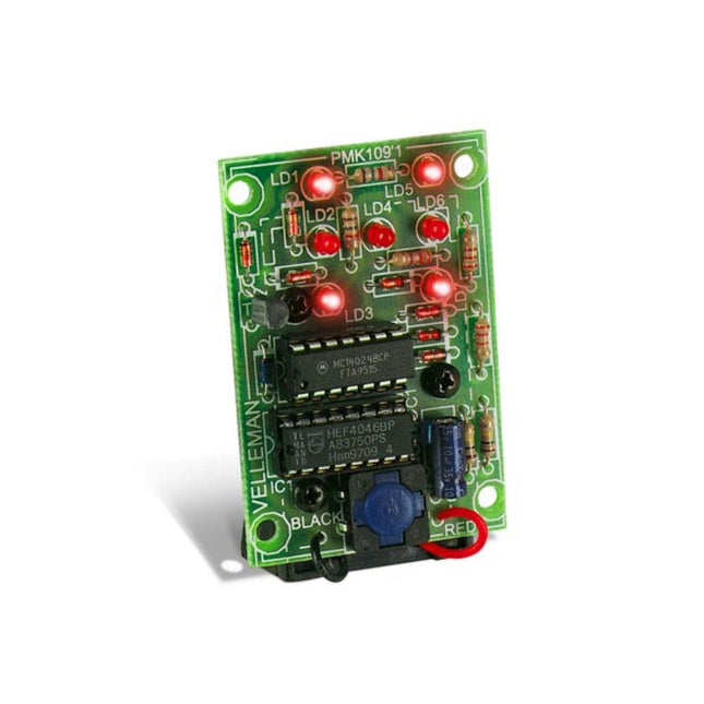
dé à lampes néon
Elektor Classics : indicateur d'accord RTTY
solutions matérielles inspirantes pour vos projets ESP
Elektor Classics : alimentation 3 A
LED RGB avec circuit de commande intégréLumière de précision : les ICLED établissent de nouvelles normes
expérience : un Thérémine analogico-numérique ?Combiner des capteurs numériques modernes avec l’intemporel générateur analogique XR2206
carte émetteur-récepteur audio ESP32 (1)Démo : lecture de fichiers WAV depuis une carte SD
infographies : Circuits et conception de circuits 2025
petit mixeur audioUne conception polyvalente et modulable
minuteur intelligent pour éclairage d’escalierÉconomisez encore plus sur votre facture d’énergie !
modernisez vos voletsContrôlez les systèmes Velux avec un ESP32 et MQTT
chauffe-pieds à transistorsConfort économe en énergie
le quadricoptère M5Stamp Fly est-il le prochain drone Tello ? (Revue)
optimiser la portée Wi-Fi de l’ESP32-C3 SuperMiniUne modification d’antenne simple et efficace
station de soudage à air chaud ZD-8968Un outil de travail économique ou uniquement de l'air chaud ?
testeur de radar de reculDétecter les pannes du système d’aide au stationnement d’un véhicule
Elektor GREEN en GOLD leden kunnen deze uitgave hier downloaden.
Nog geen lid? Klik hier om een lidmaatschap af te sluiten.
Digitale belasting voor grote stromenvan noodzaak tot innovatie
Stemmenroverinstant karaoke-schakeling
Audio A/B-keuzeschakelaar met versterkingsregelingschakelt tussen microfoon- en lijningangen
Beter laden voor de LIR2032wees lief voor uw knoopcellen
Simpele aanraaksensorenmaak ze zelf – voor elke microcontroller
Universele infraroodschakelaartweede leven voor oude afstandsbedieningen
Microcontroller-gestuurde loeidoosspeelse geluiden met een microcontroller
USB-accu-interface
Low-power apparaten voeden met een powerbankanti-afschakel-schakeling
Kleine klasse-A audioversterker met stroomuitgangstuur luidsprekers aan met stroom in plaats van spanning
Pseudo-symmetrische modulehoge CMRR met asymmetrische audioverbindingen
Automatische NiMH-laderlaad al uw accu’s in één keer!
Thyristorgebaseerde voedingsbeveiliging
Schakelaar met vingerafdruk-sensornuttige identiteitscontrole
DC/DC-converter voor 3 Aeen upgrade voor vaste-spanningsbronnen
Bewaking voor een boilerspannings- en stroomdetectie voor AC-kabels
Verzwakkers voor audiosignalen (1)instelbaar met jumpers
Poets uw acculader op (1)niet weggooien maar ombouwen!
Een print voor ‘de Blauwe’print voor Alps-motorpotmeter met terugkoppeling
50Hz-referentie uit 60Hz-netspanningzo gebruikt u 50Hz-elektronica in 60Hz-landen
Digitale isolatoreneenvoudige realisatie van galvanische isolatie
Compacte 12W-hifi-monoversterkerklein maar krachtig
Zaagtandgenerator met LM386
Driefasen-generatormet Raspberry Pi Pico
Deuropener voor muzikaal getalenteerden
Elektor-klassieker: Surf Synthesizerzeewatersportachtergrondgeluidgenerator (zwsaggg)
Poets uw acculader op (2)niet weggooien maar ombouwen!
Lampstroom-monitormet Raspberry Pi Pico
Infrarood-telegrafie
Fnirsi SWM-10repareer zelf uw accupacks met dit intelligent draagbaar puntlasapparaat
Stereo audio-codec voor ESP32 en co.geen angst voor audio-meettechnologie
Soldeertechniekendoe het meteen goed!
Verzwakkers voor audiosignalen (2)geschakeld met relais
USB-C voedingstroom uit USB-C voedingsadapters
Drie schakelingen met twee en drie teller-IC’s4017’s werken samen
Actieve componenten – de diode
Timer voor extreem lange tijdeninstellen en vergeten!
Jack in en jack uiteen handige insert-optie voor audioschakelingen
ESP32 met één Li-ion-cel
Hexadoku
Elektor GREEN en GOLD leden kunnen deze uitgave hier downloaden.
Nog geen lid? Klik hier om een lidmaatschap af te sluiten.
Project-update: ESP32-gebaseerde energiemeterwe gaan verder met het prototype
Optimalisatie van balkon PV-centralesoverwegingen, interessante feiten en berekeningen
ESP32 met OpenDTU voor balkoncentralesgegevens van kleine omvormers via MCU’s uitlezen
Regelbare lineaire labvoeding0...50 V / 0...2 A + dubbele symmetrische voeding
Energieopslag – vandaag en morgeneen vraaggesprek met Simon Engelke
2024: een AI-odysseehet houdt nog lang niet op
Bluetooth LE op de STM32meetwaarden op afstand uitlezen
Mensvriendelijk slim keuken-voorraadsysteem
MAUI: programmeren voor PC, tablet en smartphonehet nieuwe framework in theorie en praktijk
ChatMagLevkunstmatig intelligente levitatie
Eenvoudige PV-regelaarbouw je eerste, volledig functionele PV-energiebeheersysteem
Koude-kathode-buizenvreemde onderdelen
Uit het leven gegrepennostalgie
Alle begin......bekijkt de FET
CAN-bus voor de Arduino UNO R4: een tutorialtwee UNO R4’s nemen de bus!
Elektor infographicvoeding en energie
Vergelijking van vermogensdichtheid en vermogensefficiëntie
Aluminium elektrolytische condensatorenstoringspotentieel in audiotechnologie
USB testen en metenmet de Fnirsi FNB58
De Pixel Pump pick&place-tooleenvoudiger handmatige assemblage van SMT-printen
Oost West Lab Bestnog niet zo lang geleden, in een land heel ver van hier...
“In de wereld van ethiek in elektronica kunnen zelfs kleine stappen een aanzienlijke invloed hebben.”
Ethiek in elektronicade OECD Guidelines en het Lieferkettensorgfaltspflichtengesetz
Chadèche: slimme NiMH-(ont)laderlezersproject in het kort
Project 2.0correcties, updates en brieven van lezers
Deze zeer gevoelige picoammeter is ontworpen voor het meten en loggen van zeer kleine stromen tot in het pA-bereik – waardoor het een ideaal instrument is voor wetenschappelijke en onderzoekstoepassingen, waaronder natuurkunde, materiaalkunde en elektronenmicroscopie.
De SPA100, met alle functies voor een betaalbare prijs, combineert gevoeligheid, nauwkeurigheid en stabiliteit om gebruikers in staat te stellen lage stromen met hoge precisie te meten en gemakkelijk biaspanningen voor experimenten te genereren. De SPA100 is ook te gebruiken als ultrahoge weerstandsmeter, die tot in het teraohm-bereik nauwkeurig meet.
De SPA100 wordt via USB aangesloten op een PC en maakt gebruik van de gratis software SPA, waarmee gebruikers eenvoudig metingen kunnen meten, grafieken kunnen maken en meetwaarden met tijdstempels en informatie over meetstabiliteit kunnen vastleggen.
Specificaties
Ingang: ±2 mA tot ±200 pA in 8 bereiken
Nauwkeurigheid en resolutie (2 Hz):
±2 mA bereik: ±0,1%, resolutie <20 nA
±200 uA bereik: ±0,1%, resolutie <2 nA
±20 uA bereik: ±0,2%, resolutie <200 pA
±2 uA bereik: ±0,2%, resolutie <20 pA
±200 nA bereik: ±0,5%, resolutie <2 pA
±20 nA bereik: ±0,5%, resolutie <200 fA
±2 nA bereik: ±1,0%, resolutie <20 fA
±200 pA bereik: ±1,5%, resolutie <2 fA
Bemonsteringssnelheid: 2 Hz (18 bit) of 10 Hz (16 bit)
Verstelbaar filter: 1 Sample tot 64 Samples
Uitgangsspanning: -40 V tot +40 V (in stappen van 1 V), uitgangsweerstand 2,7 Kohm
Weerstandsmeting: ~1 Kohm tot 40 Tohm (bijv. 40 V bron, 1 pA meting)
Nauwkeurigheid: >±0,5% 1 Mohm tot 1 Tohm
Gevoed via USB 2.0 (instrument verbruikt tot 0,3 A tijdens gebruik)
Inbegrepen
1x SPA100 Source Picoammeter
1x USB-kabel
Downloads
Manual
Software
The SQ series of handsfree probes from Sensepeek have a lower point of gravity making them even more stable compared with the original SP series of handsfree probes. All probes in the SQ series are also insulated and can be used handheld as any traditional probe but their full potential is used when measuring handsfree.
The SQ series of oscilloscope probes also includes more ground options, have probe tip protection, longer cable and support for oscilloscopes with automatic scaling (10:1).
All the loved features of handsfree measurement, exchangeable fine pitch spring tipped test needle, color-coded cable holders and the minimalistic design is maintained to make traditional sized and handheld probes obsolete.
Both length and weight of the SQ probes are perfectly balanced to be used with PCBite PCB holders and base plate which is a must for handsfree function.
Features
Passive 10:1 probe with support for oscilloscopes with automatic scaling
Spring-loaded test needle for fine pitch measurements
Multiple ground options
Color coded cable holders
Probe tip protection
Insulated, can be used handheld
Improved probe holder for handsfree measurement when used with PCBite PCB holders
Included
1x SQ500 500 MHz probe with spring tipped test needle
1x SQ probe holder for handsfree measurement
1x Testhook with detachable cables (5 cm & 10 cm) for convenient ground connection
1x Alligator cable for convenient ground connection
1x Standard ground spring, for handheld measurements at rated bandwidth
1x Unique ground spring, for total handsfree measurements at rated bandwidth
1x Set of color coded cable holders (4 colors)
1x Probe tip protection
1x Extra test needle
Downloads
User Guide SQXX0 Rev1.1
Le téléchargement intégral de ce numéro est disponible pour nos membres GOLD et GREEN sur le site Elektor Magazine !
Pas encore membre ? Cliquez ici.
carte émetteur-récepteur audio ESP32 (2)Transmission audio sans fil
émetteur AM par inductionUtiliser les PIO du Pico dans un croquis Arduino
les protocoles sans filUn guide technique
suivi de satellites avec LoRaTinyGS, le réseau open source qui capte les données spatiales
télécommande par sms compatible 4GContrôlez votre équipement à distance
sonde haute vitesseMesure à haute impédance jusqu’à 200 MHz
sur le vifKafka
KrakenSDR
tests de performance avec le RP2350Pico 2 : une vraie amélioration ?
mesures de champ électrique sans contact (2)Un vibromètre laser pour l’analyse des vibrations de la membrane
quartz et oscillateursAméliorer la précision des quartz grâce au choix des condensateurs
démarrer en électroniqueCI audio originaux
se lancer dans le codage d'un projet DIY
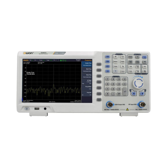
SPECTRAN® V6 MobileAnalyseur de spectre temps réel modulaire et configurable pour des mesures fiables sur l’ensemble des plages de fréquences
l’avenir de l’IA repose sur le siliciumEntretien avec Anastasiia Nosova
nœud de capteurs autonome v2.0 (architecture du système)Plateforme de mesure autonome alimentée par énergie solaire, avec GPS intégré, LoRaWAN et plus encore
positionnement précisTests du sondage de canal Bluetooth
développement logiciel piloté par les tests
voiture miniature contrôlée par SmartphoneWi-Fi + ESP32 + Smartphone = contrôle à distance
2025 : une odyssée de l’IAModèles de raisonnement en IA : la révolution de la chaîne de pensée
contrôleur de charge solaire avec MPPT (3)Logiciel et mise en service
caméra Web Raspberry Pi ZeroStreaming avec VPN ZeroTier
Le téléchargement intégral de ce numéro est disponible pour nos membres GOLD et GREEN sur le site Elektor Magazine !
Pas encore membre ? Cliquez ici.
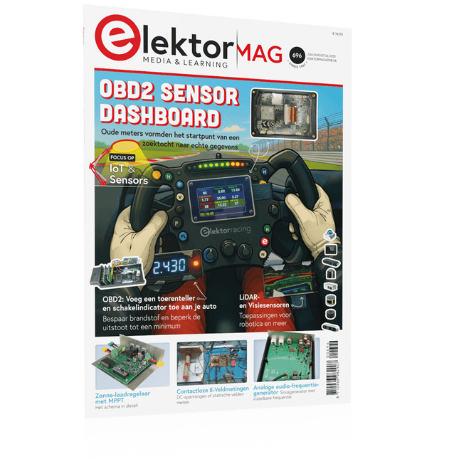
tableau de bord OBD2Des cadrans anciens aux données en temps réel
OBD2 : ajoutez un compte-tours et un indicateur de changement de vitesse à votre voitureRétro, mais extrêmement utile
capteurs de vision et LiDAR pour la robotique
Sensor+Test 2025 et PCIM 2025
mesures sans contact du champ électrique (1)Membrane vibrante pour mesurer des tensions continues ou des champs électriques statiques
détecteur de courrier sans filCapteurs optiques, radars… quelques options à explorer
Elektor Mini-WheelieUn robot auto-équilibré
cellules solairesDrôles de composants, la série
premiers pas avec un capteur radar moderneUn capteur précis qui ne passe pas inaperçu
sur le vifUsine de papier
CybersécuritéDes temps difficiles pour les hackers
Infographie : IdO et capteurs
le Bluetooth 6.0 pour des applications de télémétrie amélioréesCette nouvelle version offre des fonctions de localisation améliorées
découvrez la communication sans fil avec BeagleY-AI
Projet 2.0Corrections, mises à jour et courrier des lecteurs
démarrer en électronique……Conclusion sur les ampli-op
un puissant assistant de codage de l'IAAccélérez votre développement avec Continue et Visual Studio Code
contrôleur de charge solaire avec MPPT (2)Le circuit
détecteur d'obstacles à ultrasonsUn projet simple pour aider les malvoyants
une odyssée de l'IABilan du premier semestre
synthétiseur MIDI autonome Raspberry Pi (3)plus intelligent avec une interface utilisateur
Meshtastic : un projet de démoUn réseau intelligent de noeuds LoRa
générateur analogique de fréquences audioGénérateur de signaux sinusoïdaux de haute qualité à fréquence réglable
Elektor GREEN en GOLD leden kunnen deze uitgave hier downloaden.
Nog geen lid? Klik hier om een lidmaatschap af te sluiten.
OBD2-sensordashboardOude meters vormden het startpunt van een zoektocht naar echte gegevens
OBD2: voeg een toerenteller en schakelindicator toe aan je autoRetro, maar uiterst nuttig
LiDAR- en Visiesensoren voor Robotica
Sensor+Test 2025 en PCIM 2025
Contactloze E-Veldmetingen (1)Een Trillende Membraan voor het Detecteren van Gelijkspanningen of Statische Elektrische Velden
Draadloze brievenbusmeldervan optische sensoren tot radar: enkele mogelijkheden
Elektor Mini-Wheelieeen zelfbalancerende robot
ZonnecellenVreemde onderdelen, de serie
Aan de slag met een moderne radarsensorStaat een nauwkeurige meting op uw radar?
Uit het leven gegrepenpapierfabriek
CybersecurityZware tijden voor hackers
Infographics: IoT en sensoren 2025
Bluetooth 6.0 brengt verbeterde toepassingen voor afstandsbepalingNieuwe versie biedt betere apparaatpositionerings- en -locatieservices
Draadloze communicatie verkennen met BeagleY-AI
Err-lectronicsCorrecties, updates en lezerspost
Alle begin......sluit het thema opamps af
Een krachtige AI-codeerassistentsneller ontwikkelen met Continue en Visual Studio Code
Zonne-laadregelaar met MPPT (2)Het schema
Ultrasone obstakeldetectoreen eenvoudig project om slechtzienden te helpen
2025: Een AI-odysseeHalfjaaroverzicht
Raspberry Pi Standalone MIDI-synthesizer (3)Het slimmer maken en een gebruikersinterface toevoegen
Meshtastic: een demonstratieprojectEen slim netwerk van LoRa-radio's
Analoge audio-frequentiegeneratorHoogwaardige sinusgenerator met instelbare frequentie
311 Schakelingen is het twaalfde boek uit de gerenommeerde 300-reeks van Elektor. Dat betekent ook dit keer weer een onuitputtelijke bron van inspiratie voor elke elektronicus, hobbyist of professional, en een boek dat in geen enkele boekenkast mag ontbreken!
311 Schakelingen bevat een ruime collectie schakelingen, ideeën, tips en trucs op alle denkbare terreinen van de elektronica: audio en video, hobby en modelbouw, hoogfrequenttechniek, huis en tuin, meten en testen, microprocessor, PC-hard- en software, voedingen en acculaders, en natuurlijk een rubriek 'diversen' voor alles wat niet in een van de andere rubrieken past. Het boek biedt complete oplossingen voor talloze problemen, of de aanzet voor eigen ontwikkelingen.
311 Schakelingen is samengesteld uit de Halfgeleidergidsen van 2009, 2010 en 2011. De Halfgeleidergids is het jaarlijkse dubbeldikke juli/augustusnummer van het maandblad Elektor. Het boek is dus voor een groot deel gebaseerd op inzendingen van lezers van Elektor, aangevuld met bijdragen uit het Elektor-lab.
Eén ding hebben alle elektronische schakelingen en apparaten gemeen: de werking ervan staat of valt met de voeding. Alleen al daarom verdient deze deelschakeling speciale aandacht. Dit boek behandelt principes en schakelingen uit de praktijk van de voedingstechniek. Geheel in overeenstemming met de huidige trend gaat de auteur in het bijzonder in op 'mobiele' voedingen en op de techniek van schakelende voedingen. Ook wordt aandacht besteed aan het feit dat constante-stroombronnen ten opzichte van spanningsbronnen een steeds belangrijker rol gaan spelen. Naast de vereiste theoretische achtergronden en principes voor het ontwerpen en bouwen van eigen voedingsschakelingen biedt dit boek ook praktische toepassingsvoorbeelden, zoals het vervangen van defecte nettransformatoren, de voeding voor elektronica tijdens fietstochten of het aansturen van LED‘s in de verlichtingstechniek. Auteur Franz Peter Zantis is afgestudeerd als ingenieur communicatietechniek en houdt zich als elektronicus bezig met energie-installaties. Tijdens een onderzoeksproject heeft hij zich grondig verdiept in de stroomvoorziening van zelfstandig werkende apparaten en hij heeft talrijke artikelen over schakelende voedingen gepubliceerd.
Dit boek is bedoeld voor diegenen die zich bezig houden met geluidsversterking en geluidsdistributie. Het gaat in op de akoestische eigenschappen van open, halfopen en omsloten ruimten. Belangrijk is hoe luidsprekers aangepast kunnen worden op allerlei omgevingen. Meestal moet men een keuze maken uit het aanbod van luidsprekers en microfoons. De vraag is dan welke luidspreker en microfoon de juiste keuze zijn. En hoe deze moeten worden opgesteld waarbij spraak- en muziekverstaanbaarheid en de maximaal haalbare versterking in de live-situatie de belangrijkste criteria zijn. Dit boek geeft antwoord op die vragen.Verder wordt de lezer meegenomen naar het ontwerpen van luidsprekers op basis van de T/S parameters. Met eenvoudige software is het mogelijk akoestische en mechanische elementen van een luidspreker met de eventuele behuizing te vertalen naar de elektrische analogieën, zodat de luidspreker op de PC gesimuleerd kan worden. Aan de hand van rekenvoorbeelden worden bovenstaande simulaties ondersteund. Tot slot zijn in de referentielijst een aantal internetlinks opgenomen waaruit zeer waardevolle gegevens gehaald kunnen worden.De auteur, Peter Swarte, is natuurkundig ingenieur en was werkzaam bij Philips. Momenteel is hij_eigenaar van consultancy bureau P.A.S. Electro Acoustics en is hij actief lid van zowel het NAG (Nederlands Akoestisch Genootschap) als de AES (Audio Engineering Society).
Le téléchargement intégral de ce numéro est disponible pour nos membres GOLD et GREEN sur le site Elektor Magazine !
Pas encore membre ? Cliquez ici.
un nœud de capteurs autonometransmission de données basée sur LoRa et alimentation en énergie par cellules solaires
la carte eXpansion V1.0 d'Elektorpour ESP32S3 et autres cartes XIAO
une caméra dans un train miniatureinstallation d’un module ESP32 CAM
antenne magnétique à large bande pour les grandes ondestous les émetteurs sans aucun accord
TensorFlow Lite pour microcontrôleurspar un débutant, pour les débutants
un concentrateur pour les appareils RS-422 et RS-485câbler votre bus comme une star
sonde RFWith LED Bar Graph
démarrer en électronique...…plus de montages à ampli-op
Open Variovariomètre multifonction open source pour vol en parapente
sur le vifÀ propos de prendre les choses pour acquises
relevé des compteurs d'eau basé sur l'IA (Partie 2)intégrez votre ancien compteur dans l'IdO !
agriculture intelligentedétection des nuisibles basée sur l’apprentissage machine avec connectivité IdO
Anybus CompactCom est le choix idéal pour la communication industrielle embarquée – voici pourquoi
norme de communication IQRFfiabilité des réseaux maillés sans fil à faible débit avec perte
comment construire un robot agricole intelligentquelles sont les considérations essentielles que les concepteurs de robots agricoles doivent prendre en compte et à quels défis techniques sont-ils confrontés ?
filtre coupe-bande audio à fréquence réglablesolution universelle de suppression de fréquences dans le domaine audio
le système LeoINAGPSsurveillez votre véhicule électrique
nœud LoRa alimenté par énergie solaireune solution IdO modulaire, compacte et polyvalente
AWS pour Arduino et cie. (2)transmission de données avec AWS IoT ExpressLink
projet 2.0corrections, mises à jour et courrier des lecteurs
2024 : l'odyssée de l'IAexamen des Accélérateurs IA : comparaison
extension de couverture Wi-Fi sur ESP32comment modifier simplement une antenne
Lancé en mars 2012, plus les 30 millions d'exemples nanométriques du Raspberry Pi exposés. Il s’agit d’une contribution à la révolution des technologies de l’information et d’un grand stimulant pour le développement du monde de l’électronique. Le succès de la « tarte à la framboise » (traduction littérale de Raspberry Pie) est le résultat de l'industrie micro-électronique de transformation des produits.
Eben Upton, son créateur, âme à l'origine, les acheteurs étaient presque tous des makers , adultes en général. Cependant la plupart d'entre eux étaient également des ingénieurs professionnels. Rapidité, les gens sont responsables de leurs activités personnelles lors de l'utilisation du Raspberry Pi avec une plateforme informatique stable, et ils sont également adoptés pour leur métier.
La Fondation Raspberry Pi édite un magazine édité par la communauté Raspberry Pi : le MagPi (en anglais). Le magazine aborde les passions selon la nature du numérique nano-ordonné et global. Il contient des bancs d'essai de nouveaux produits, de nombreux tutoriels et un grand nombre de projets. Les membres de la communauté Raspberry Pi participent à leur expérience.
La maison d'édition Elektor s'associe à la Fondation Raspberry Pi pour la publication dans le magazine français MagPi. Il est conçu pour assembler 84 projets publics du MagPi en développant l'utilisation du Raspberry Pi et son inspiration.
Grâce à la taille fine et aux possibilités du Raspberry Pi, les créateurs du monde sont fiers des idées des plus folles.
Partez en voyage dans un monde où est faisable !
Le Raspberry Pi à toutes les sauces pour ?
s'inspirateur des projets réalisés par les membres de la communauté
dénicher des utilisations inouïes
découvrir des accessoires et technologies diverses
entrer dans une communauté intégrée et active de Raspberry Pi
Met de JOY-iT PS1440-C-Pro krijgt u een programmeerbare laboratoriumvoeding die gelijkspanningen levert van 0,01 tot 60 V en gelijkstromen van 0,01 tot 24 A aan de spanningsuitgang.
Met het intuïtieve bedieningspaneel kunt u tot 9 verschillende gelijkspanningsinstellingen programmeren, opslaan en oproepen. U kunt ook individuele beveiligings- en begrenzingsfuncties configureren, zoals overspanningsbeveiliging. Alle instellingen kunnen eenvoudig worden aangepast via het toetsenbord en/of de draaiknop en worden duidelijk weergegeven op het kleurendisplay met hoge resolutie van 2,4 inch.
Voor verbeterde connectiviteit is de PS1440-C-Pro voorzien van een RS485-interface voor robuuste communicatie over lange afstanden. Dit maakt hem ideaal voor complexe opstellingen waar signaalstabiliteit, ruisimmuniteit en betrouwbare gegevensoverdracht cruciaal zijn. De meegeleverde connector zorgt voor een veilige verbinding, wat de algehele betrouwbaarheid en prestaties van uw laboratoriumapparatuur verbetert.
Kenmerken
Compleet apparaat klaar voor onmiddellijk gebruik
RS485-interface
Accu oplaadfunctie
Waarden kunnen gemakkelijk worden ingevoerd via het toetsenbord
Overstroom- en overspanningsbeveiliging instelbaar
Geïntegreerde RTC, NTC-temperatuursensor
Inclusief gedetailleerde documentatie in het Engels, Duits en Frans
Specificaties
Ingangsspanning
230 V
Uitgangsspanning
0-60 V
Uitgangsstroom
0-24 A
Uitgangsvermogen
0-1440 W
Nauwkeurigheid ingangsspanning
±1% + 5 cijfers
Nauwkeurigheid uitgangsspanning
±0,3% + 3 cijfers
Nauwkeurigheid uitgangsstroom
±0,5% + 5 cijfers
Accuspanning
±0,5% + 3 cijfers
Meetresolutie ingangsspanning
0,01 V
Meetresolutie van uitgangsspanning
0,01 V
Resolutie stroommeting
0,01 V
Meetresolutie accuspanning
0,01 V
Reactietijd in constante spanningsmodus
2 ms @ 0,1-5 A
Belastingregeling in constante spanningsmodus
±0,1% + 2 cijfers
Belastingregeling in constante stroommodus
±0,1% + 3 cijfers
Meetbereik elektrische lading
0-9999,99 Ah
Meetbereik energie
0-9999,99 Wh
Statistische fouten in elektrische lading en energie
±2%
Uitgangsrimpel
100 mV Vpp @ 12 V 150 mV Vpp @ 24 V
Detectiebereik temperatuursensor
?10~+100°C
Nauwkeurigheid temperatuurdetectie sensor
±3°C
Werkmodus
Trapsgewijze werking
Instelling schermhelderheid
Niveau 0-5, 6 niveaus in totaal
Toegestane werktemperatuur
−10~40°C
Afmetingen
170 x 93 x 340 mm
Inbegrepen
JOY-iT PS1440-C Voeding
2-pins connector voor RS485-interface
Netsnoer
Manual
Downloads
Datasheet
MODBUS Protocol
PC Software
Driver for Windows
High-quality soldering station with the most important tools and consumables, ideal for universal soldering applications.
Features
1-Channel Power Unit, digital, 70 W
Power unit, 1 channel with soldering iron WEP 70 and safety rest PH 70
70W solder iron with ergonomic handle and providing toolless tip change
ESD safe station, iron and heat-resistant silicon cable for safe handling
Using ET soldering tips
Standby mode and auto setback conserves energy, protects equipment
Password-protected to preserve settings
Specifications
Dimensions: 150 x 120 x 98 mm
Weight: 1.4 kg
Display: Digital LC Display
Temperature range: Adjustable from 100°C - 450°C (200°F - 850°F)
Voltage: 230 V
Channels: 1
Temperature range (depends on tool) °C: 100-450
Temperature range (depends on tool) °F: 200-850
Temperature accuracy °C: Average tip temperature can be „offset“ to +/- 5°C at idle with no load
Temperature accuracy °F: Average tip temperature can be „offset“ to +/- 9°F at idle with no load
Temperature stability °C: ±6
Temperature stability °F: ±10
Heat-up time (ca) in seconds (50-350°C / 120-660°F): 28 sec.
Heating output: 85 W
De OWON SDS1104 oscilloscoop is een praktische keuze voor engineers, technici, studenten en hobbyisten die nauwkeurige signaalanalyse nodig hebben zonder de kosten van hoogwaardige meetinstrumenten. Met een bandbreedte van 100 MHz en een samplingrate van 1 GSa/s legt hij laag- tot middenfrequente signalen betrouwbaar vast, waardoor hij zeer geschikt is voor elektronicaontwikkeling, foutopsporing en educatief gebruik.
Uitgerust met een 7-inch kleuren-TFT-display biedt de SDS1104 een duidelijke weergave van golfvormen, terwijl automatische meetfuncties en FFT-analyse gebruikers helpen om frequentie-, spannings- en timingparameters snel te beoordelen. Geavanceerde wiskundige bewerkingen, cursormetingen en meerdere triggermodi zorgen voor extra flexibiliteit, waardoor de oscilloscoop een veelzijdig hulpmiddel is voor uiteenlopende testsituaties.
Specificaties
Bandwidth
100 MHz
Sample Rate
1 GS/s
Horizontal Scale (s/div)
5ns/div - 1000s/div, step by 1 - 2 - 5
Channel
4
Display
7" color LCD, 800 x 480 pixels
Input Coupling
DC, AC and GND
Vertical Resolution (A/D)
Vertical Resolution (A/D)
Vertical Sensitivity
5mV/div - 5V/div (at input)
Trigger Type
Edge, Video
Trigger Mode
Auto, Normal and Single
Waveform Math
+, -, x, ÷, invert, FFT
Fuse
2A, T class, 250 V
Dimension (W x H x D)
301 x 152 x 70 mm
Weight
1.1 kg
Inbegrepen
1x OWON SDS1104 Oscilloscope
1x Mains power cord
1x CD Rom
1x Quickstart Guide
1x USB Cable
4x Oscilloscope probe
1x Probe Adjust
Downloads
Datasheet
Manual
Features
Channel
Single Channel Output
Total Output Power
180 W
Channel Output
0 - 60 V / 0 - 3 A × 1-CH
Display
3.7' color LCD display
Dimension
117 mm(L) × 194 mm(H) × 295 mm(D)
Weight
Approx. 5.8 kg
Interface
RS232
Specifications
Rated Output (0 ? - 40 ?)
Voltage
0 - 60 V
Current
3 A
Load Regulation
Voltage
? 0.01% + 3 mV
Current
? 0.01% + 3 mA
Power Regulation
Voltage
? 0.01% + 3 mV
Current
? 0.01% + 3 mA
Setting Resolution
Voltage
1 mV
Current
1 mA
Readback Resolution
Voltage
1 mV
Current
1 mA
Setpoint accuracy (within 12 months) (25 ? ± 5 ?)
Voltage
? 0.03% + 10 mV
Current
? 0.1% + 5 mA
Readback Resolution (25 ? ± 5 ?)
Voltage
? 0.03% + 10 mV
Current
? 0.1% + 5 mA
Ripple/Noise (20 Hz - 20 MHz)
Voltage (Vp-p)
? 4 mVp-p
Voltage (Vrms)
? 1 mVrms
Current (rms)
? 4 mArms
Output temperature coefficient (0 ? - 40 ?)
Voltage
? 0.03% + 10 mV
Current
? 0.1% + 5 mA
Readback temperature coefficient
Voltage
? 0.03% + 10 mV
Current
? 0.1% + 5 mA
Response Time
100 ?s
Storage
5 groups of data
Working Temperature
0 - 40 ?
De OWON SPS6051 ventilatorloze programmeerbare DC-voeding (150 W) levert ultrastille, uiterst nauwkeurige prestaties met een nauwkeurigheid van 10 mV/1 mA en geavanceerde warmteafvoer voor betrouwbaarheid op lange termijn. Met uitgebreide bescherming, een USB-interface met SCPI-ondersteuning voor afstandsbediening en een 2,8-inch TFT LCD-scherm, is dit de perfecte keuze voor laboratoria, elektronicatests en onderzoek.
Kenmerken
Ontwerp zonder ventilator: ultrastille werking, vermindert trillingsgeluid en minimaliseert de potentiële storingsrisico's die gepaard gaan met traditionele koelventilatoren.
Uitstekend ontwerp voor warmteafvoer: zorgt voor een gecontroleerde temperatuurstijging, waardoor langdurig gebruik onder volledige belasting mogelijk is en de levensduur van de interne componenten wordt verlengd.
Lichtgewicht en ultradun ontwerp.
Uitgangsnauwkeurigheid tot 10 mV/1 mA.
Ondersteunt het bewerken en uitvoeren van golfvormen in de lijst, met vier geheugensnelkoppelingsparameters voor snelle en gemakkelijke toegang.
Geïntegreerde beveiligingsfuncties omvatten bescherming tegen overspanning, overstroom, oververhitting en onderspanningsbeveiliging voor verbeterde veiligheid.
Ingebouwd ontladingscircuit voorkomt resterende hoogspanningsrisico's wanneer de stroom wordt uitgeschakeld.
USB-communicatie-interface met SCPI-protocolondersteuning, waardoor pc-programmering en afstandsbediening mogelijk zijn voor vereenvoudigd gebruikersbeheer.
2,8-inch TFT LCD-scherm
Specificaties
Model
SPS6051
SPS3081
Nominaal vermogen (0°C-40°C)
Spanning
0-61 V
0-31 V
Stroom
0-5,1 A
0-8,1 A
Vermogen
150 W
120 W
Belastingsregeling
Spanning
≤30 mV
Stroom
≤20 mA
Vermogensregeling
Spanning
≤30 mV
Stroom
≤20 mA
Resolutie instellen
Spanning
10 mV
Stroom
1 mA
Leesresolutie
Spanning
10 mV
Stroom
1 mA
Instelnauwkeurigheid (25°C ±5°C)
Spanning
≤0,05% ±20 mV
≤0,1% ±20 mV
Stroom
≤0,05% ±20 mA
≤0,2% ±20 mA
Leesnauwkeurigheid (25°C ±5°C)
Stroom
≤0,05% ±20 mV
≤0,1% ±20 mV
Spanning
≤0,05% ±20 mV
≤0,2% ±20 mA
Rimpeling/ruis
Spanning
≤30 mVp-p
≤30 mVp-p
Spanning
≤4 mVrms
≤5 mVrms
Stroom
≤10 mAp-p
≤30 mAp-p
Uitgangstemperatuurcoëfficiënt (0°C-40°C)
Spanning
100 ppm/°C
Stroom
200 ppm/°C
Teruglezen temperatuurcoëfficiënt
Spanning
100 ppm/°C
Stroom
200 ppm/°C
Responstijd (50-100% nominale belasting)
≤1,0 ms
Opslag
4 groepen gegevens
Werktemperatuur
0-40°C
Display
2,8-inch LCD-kleurenscherm
Interface
USB
Afmetingen (B x H x D)
82 x 142 x 226 mm
Gewicht
1,8 kg
Inbegrepen
1x OWON SPS6051 Voeding
2x Testleads
1x Netsnoer
1x Manual
Downloads
Datasheet
User Manual
Programming Manual
PC Software
Het boek beschrijft de werking van digitale circuits vanaf schakelingen met poorten tot aan de werking van een processor. Van elke schakeling of systeem kan de werking worden gesimuleerd. Hierbij wordt het gedrag van componenten en het verloop van signalen in de tijd op ingangen, uitgangen en relevante verbindingslijnen zichtbaar gemaakt. Zo wordt in detail gevisualiseerd wat het gedrag is van de hardware als er een instructie wordt uitgevoerd.Het boek is opgebouwd uit drie modules die de volgende onderwerpen behandelen:Basismodule
Poorten en combinatorische schakelingen.
Hoe rekent een computer?
Hoe werkt een rekenmachine?
Module Digitale Techniek
Hoe ontwerp je combinatorische schakelingen m.b.v. Boole-algebra?
Sequentiële schakelingen en het ontwerpen van ‘Finite State Systems’.
Complexe schakelingen als decoders, multiplexers, asynchrone en synchrone tellers.
Module Computerarchitectuur
Hoe werkt een ‘loopje’ precies? If-then-else, while en for loops.
De Harvard-architectuur.
Hoe verloopt de communicatie tussen de aanroeper en de aangeroepene bij aanroep van een procedure?
Bij de module Computerarchitectuur worden programma’s in de taal assembler geschreven. Hierbij wordt gebruik gemaakt van een instructieset van slechts 15 instructies.WebsiteHet boek wordt ondersteund door de website: www.science.uva.nl/amstel/SIM-PL. De SIM-PL software en de componenten die nodig zijn voor de simulaties kunnen hiervandaan worden gedownload. Ook staan hier antwoorden op vragen en vraagstukken. Verder zijn op deze site collegesheets voor docenten en voorbeelden van tentamens beschikbaar.DoelgroepenVAN 0 EN 1 TOT PROCESSOR is geschreven voor iedereen die geïnteresseerd is in de basisprincipes waarop de werking van computers berust. Het boek is zeer geschikt voor studenten Informatica, Technische Informatica en E-technology in het hoger onderwijs en het MBO. Het boek kan worden ingezet bij vakken als Digitale Techniek, Embedded Systems en Architectuur & Computerorganisatie. Delen van de eerste drie hoofdstukken zijn opgenomen in modules voor de vakken Informatica, NLT en Wiskunde D in het voortgezet onderwijs.Ben Bruidegom is werkzaam bij het AMSTEL-Instituut van de Universiteit van Amsterdam als ontwikkelaar van educatieve hard- en software en docent aan het College of Science van deze universiteit. Hij heeft tientallen jaren ervaring op het gebied van de technische automatisering en het ontwikkelen van onderwijs hiervoor.