The Red Pitaya (STEMlab) is a credit card-sized, open-source test and measurement board that can be used to replace most measurement instruments used in electronics laboratories. With a single click, the board can transform into a web-based oscilloscope, spectrum analyser, signal generator, LCR meter, Bode plotter, and microcontroller.
The Red Pitaya (STEMlab) can replace the many pieces of expensive measurement equipment found at professional research organisations and teaching laboratories. The device, that based on Linux, includes an FPGA, digital signal processing (DSP), dual core ARM Cortex processor, signal acquisition and generation circuitry, micro USB socket, microSD card slot, RJ45 socket for Ethernet connection, and USB socket – all powered from an external mains adaptor.
This book is an introduction to electronics. It aims to teach the principles and applications of basic electronics by carrying out real experiments using the Red Pitaya (STEMlab). The book includes many chapters on basic electronics and teaches the theory and use of electronic components including resistors, capacitors, inductors, diodes, transistors, and operational amplifiers in electronic circuits. Many fun and interesting Red Pitaya (STEMlab) experiments are included in the book. The book also makes an introduction to visual programming environment.
The book is written for college level and first year university students studying electrical or electronic engineering.
Deze bundel bevat de Red Pitaya STEMlab 125-14 PRO Gen 2 Starter Kit en het nieuwe boek "Experimenteren met Red Pitaya STEMlab Gen 2".
De Red Pitaya STEMlab 125-14 PRO Gen 2 Starter Kit is een krachtig en flexibel platform voor signaalverwerking, data-acquisitie en elektronische meettoepassingen. Deze kit is ontworpen voor ingenieurs, ontwikkelaars, onderzoekers en docenten en biedt alles wat nodig is om te beginnen met het bouwen van geavanceerde meet- en besturingssystemen.
De kern van de kit wordt gevormd door het STEMlab 125-14 PRO Gen 2-bord, een geüpgradede en ultralichte ontwikkeling. Aangedreven door de Xilinx Zynq-7010 SoC met 512 MB RAM, combineert het de programmeerbaarheid van een FPGA met de verwerkingskracht van een ARM-processor om hoogwaardige instrumentatie en aangepaste signaalverwerkingsoplossingen mogelijk te maken.
Het bord biedt een 14-bits ADC- en DAC-resolutie, een bemonsteringsfrequentie van 125 MS/s, een ingangsbereik van ±20 V en een bandbreedte tot 60 MHz. Dankzij de verbeterde ruisarme analoge front-end, USB-C-connectiviteit en het compacte ontwerp is het geschikt voor veeleisende toepassingen zoals RF-ontwikkeling, radarsystemen, fotonica-onderzoek, softwaregedefinieerde radio (SDR) en industriële automatisering.
De Starter Kit bevat alle essentiële accessoires voor onmiddellijk gebruik: een microSD-kaart met vooraf geïnstalleerd besturingssysteem, voeding, ethernetkabel voor toegang op afstand, twee 100 MHz-oscilloscoopprobes en SMA-naar-BNC-adapters voor flexibele signaalaansluitingen.
De Red Pitaya STEMlab 125-14 PRO Gen 2 Starter Kit is een uitstekend platform voor rapid prototyping, FPGA-ontwikkeling, meetinstrumentatie en geavanceerde elektronica-experimenten.
Kenmerken
14-bits ADC- en DAC-resolutie
125 MS/s samplingfrequentie
±20 V ingangsbereik
Tot 60 MHz bandbreedte
Xilinx Zynq-7010 SoC (FPGA + ARM-processor)
512 MB RAM
Ruisarme analoge front- en back-ends
Toepassingen
RF-ontwikkeling en -testen
Radar- en draadloze systemen
Software Defined Radio (SDR)
Fotonica en optisch onderzoek
Industriële automatisering en besturingssystemen
Signaalanalyse en instrumentatie
Snel prototypen van elektronische meetsystemen
Specificaties
Processor
Dual-core ARM Cortex-A9
FPGA
AMD Xilinx Zynq-7010 SoC
RAM
512 MB (4 Gb)
Opslag
microSD-kaart (tot 32 GB)
Besturingssysteem
Linux-gebaseerd Red Pitaya OS
ADC-resolutie
14-bits
DAC Resolutie
14-bits
Bandbreedte
60 MHz (DC)
Sampling rate
125 MS/s
Analoge ingangskanalen
2
Analoge uitgangskanalen
2
Ingangsspanningsbereik
±1 V (LV) / ±20 V (HV)
Ingangsimpedantie
1 MΩ / 10 pF
Uitgangsspanningsbereik
±1 V
Ethernet
1x Gigabit Ethernet (RJ45)
USB
2x USB-C 2.0 (voor voeding en console)
Digitale I/O
16x GPIO (3,3 V)
Communicatie-interfaces
I²C, SPI, UART, CAN
Voeding
5 V/3 A via USB-C
Afmetingen
106,8 x 60,0 x 17,9 mm
Inbegrepen
1x Red Pitaya STEMlab 125-14 PRO Gen 2 Board
2x 100 MHz oscilloscoopprobes
2x SMA-naar-BNC-adapters
1x microSD-kaart met voorgeïnstalleerd besturingssysteem
1x USB-C-voeding
1x Ethernetkabel
Downloads
Documentation
Schematics
Book: Experimenting with Red Pitaya STEMlab Gen 2
Met dit nieuwe boek gaat Red Pitaya verder dan een veelzijdig board. Het wordt een krachtig laboratoriuminstrument voor nauwkeurige metingen, analyse en besturing.
Van de basisprincipes van elektronische projectontwikkeling, monitoring, besturing en ontwerp tot testen: dit boek begeleidt u stap voor stap door alles wat u moet weten om het volledige potentieel van de Red Pitaya-hardware en -software te benutten.
Het boek presenteert real-time, FPGA-gebaseerde projecten die op een PC worden ontwikkeld met de Vivado-omgeving en vervolgens naar de Red Pitaya worden overgebracht voor uitvoering en testen.
U leert over verbeterde prestaties, uitgebreide I/O-mogelijkheden, verbeterde FPGA-functionaliteiten en geavanceerde connectiviteitsopties die nieuwe mogelijkheden openen voor nauwkeurige metingen, monitoring en besturing in uw embedded toepassingen.
In dit boek ontdekt u:
Een diepgaande verkenning van de Red Pitaya-architectuur en het hardwareontwerp
Elektronische experimenten met Red Pitaya voor meting en monitoring
Praktische projecten met de programmeertaal Python
Praktische richtlijnen voor FPGA-programmering met Red Pitaya
Red Pitaya FPGA-projecten met Verilog HDL in de Vivado IDE
Praktisch ontwerp van elektronische projecten inclusief meting en testen
Stapsgewijze voorbeelden die theorie en praktijk met elkaar verbinden
Of u nu uw eigen elektronische schakelingen ontwerpt, tools voor signaalanalyse ontwikkelt of real-time besturings- of monitoringssystemen creëert, dit boek biedt u de kennis en het vertrouwen om het Red Pitaya-platform volledig te leren kennen en aan te passen.
Arduino Uno est une plaque de développement de microcontrôleur, avec superposition de code source (matériel, EDI et bibliothèques). Arduino est l'une des plus grandes communautés de programmeurs, d'ingénieurs et d'électroniciens, de passionnés et d'étudiants universitaires. Merci pour vos bibliothèques, le programme devient adapté à votre jeune enfant et la rapidité. Les bibliothèques entièrement testées et fonctionnelles facilitent le test des programmes.
Le Raspberry Pi 4, une version récente du système nano-ordonné, est utilisé pour les appareils multimédias, ainsi que pour les applications industrielles, robotiques, domestiques et commerciales. Grâce à la connectivité Wi-Fi et Bluetooth, votre Raspberry Pi 4 est parfait pour la commande et la surveillance à distance via Internet.
Ce livre avec une œuvre de Raspberry Pi 4 et de l'Arduino Uno dans des applications de régulation avec l'algorithme PID. Après avoir examiné la théorie des systèmes de régulation et des systèmes intégrés, l'évaluation des fonctions du projet et les tests de pilotage des systèmes de régulation PID en temps réel. Le timing et la structure des paramètres PID et le timing et la structure des systèmes détaillés et détaillés (schémas fonctionnels, schémas de circuits, algorithmes de régulation PID, liste complète des cartes).
Ces projets s'appuient constamment sur la théorie et les applications des régulateurs PID. C'est un simple modificateur pour d'autres applications. Les projets pour le Raspberry Pi 4 sont adaptables selon les différents modèles de la famille Raspberry Pi.
Le livre couvre les sujets suivants :
Systèmes de régulation et systèmes ouverts et fermés
Capteurs analogiques et numériques
Fonctions de transfert et de système en continu
Enregistrements temporels des systèmes du 1er et du 2ème ordre
Systèmes discrets (nombres)
Les régulateurs PID sont des systèmes à température continue
Numéros PID des régulateurs
Régulation de température selon Raspberry Pi et Arduino Uno
Régulation de température PID à l'aide de Raspberry Pi et Arduino Uno
Pilotage continu de moteurs utilisant Raspberry Pi et Arduino Uno
Régulation PID pour surveiller le niveau du Raspberry Pi et de l'Arduino Uno
Régulation PID pour piloter une LED avec Raspberry Pi et Arduino Uno
A Hands-on Guide to Crafting Your Own Power Plant
The book you are about to read provides a step-by-step guide for building a renewable energy power plant at home. Our goal was to make the book as practical as possible. The material is intended for immediate application with a small amount of theory. Yet, the theory is important as a foundation that saves time and effort by disabusing the readers of potential misconceptions. Specifically, upon having a firm understanding of photovoltaic physics, you will not be inclined to fruitlessly search for 90% efficient solar panels!
We want our readers to be the “doers”. If the book gets covered in grime and some pages become torn while you are building your power plant – this is the best compliment to us. The book covers solar and wind energy. Also, a curious power source based on manure is discussed as well, giving the doers an opportunity to further develop the manure fuel cell.
It is important to note that there are many companies offering installation of complete solar solutions. Upon installing the panels, the system is not owned by the customer. Therefore, there is no freedom for experimentation and optimization. Also, none can beat the cost of a DIY solution as well as the ultimate satisfaction.
All that is written here is a result of us building a renewable energy solution in Southern California. As the book was completed, the energy began flowing!
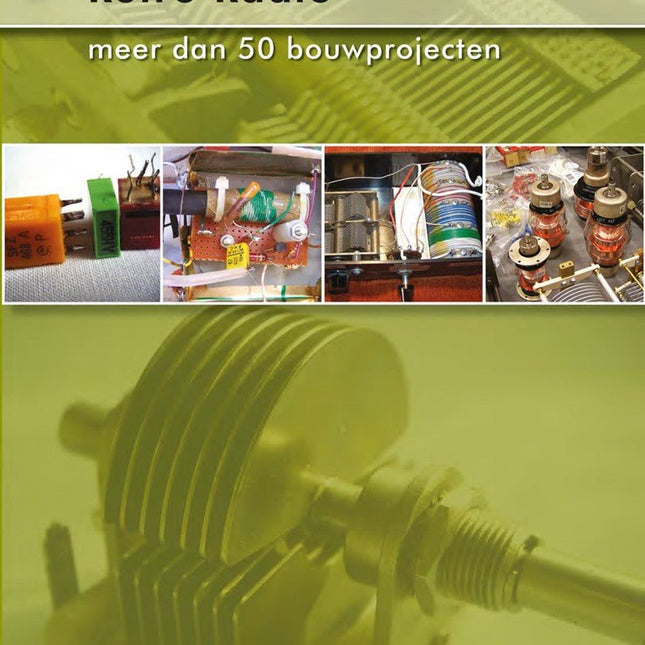
Retro Radio is een praktijkboek voor beginners en uitermate geschikt voor iedereen die wel eens een radio zou willen bouwen en meer wil weten over de radiotechniek. Na een inleiding in de beginselen van de techniek en de radio-ontvangst op de korte golf komen een aantal eenvoudige radio-ontwerpen aan bod. Het gaat om radio’s voor de middengolf en korte golf, waarbij de KG radio’s geschikt zijn voor de ontvangst van Single Side Band signalen. Het “retro” karakter dankt het boek aan het feit dat de gepubliceerde schakelingen klassiekers zijn uit de analoge radiotechniek. Ze zijn geïnspireerd door schakelingen uit de jaren ’50 en de begintijd van de radiotechniek. De auteur grijpt terug op de radio in zijn meest elementaire vorm. Al het “overbodige” is uit de schakelingen weggelaten. Er wordt gewerkt met spoelen, afstemcondensatoren, keramische filters en spoelfilters. Alle schakelingen zijn gebouwd met gewone transistors en een veldeffecttransistor. Elektronische chips worden niet gebruikt. Overigens is aan de nieuwste ontwikkelingen niet helemaal voorbij gegaan. Er is ook een SDR ontwerp opgenomen. Een greep uit de schema’s: een kristalradio, verschillende middengolf ontvangers (ook met een radiobuis), een “oer” schema geïnspireerd door de begintijd van de radio, twee korte golf ontvangers met SSB (2-12 MHz en 6-17 MHz) en een ontvanger voor de 80 meter band. Verder is in dit boek bijzonder veel aandacht besteed aan de praktische constructie van de radio’s en zijn er verschillende eenvoudige meetapparaten beschreven die dienst kunnen doen bij het ontwerpen en testen van radio’s (meetzender, absorptiemeter, transistortester e.d.).
Quite unintentionally a one-page story on an old Heathkit tube tester in the December 2004 edition of Elektor magazine spawned dozens of ‘Retronics’ tales appearing with a monthly cadence, and attracting a steady flow of reader feedback and contributions to the series. Since launching his Retronics columns, Elektor Editor Jan Buiting has never been short of copy to print, or vintage equipment to marvel at.
This book is a compilation of about 80 Retronics installments published between 2004 and 2012. The stories cover vintage test equipment, prehistoric computers, long forgotten components, and Elektor blockbuster projects, all aiming to make engineers smile, sit up, object, drool, or experience a whiff of nostalgia.
To reflect that our memories are constantly playing tricks on us, and honoring that “one man’s rubbish is another man’s gem”, the tales in the book purposely have no chronological order, and no bias in favor of transistor or tube, microprocessor or discrete part, audio or RF, DIY or professional, dry or narrative style.
Although vastly diff erent in subject matter, all tales in the book are told with personal gusto because Retronics is about sentiment in electronics engineering, construction and repair, be it to reminisce about a 1960s Tektronix scope with a cleaning lady as a feature, or a 1928 PanSanitor box for dubious medical use.
Owners of this book are advised to not exceed one Retronics tale per working day, preferably consumed in the evening hours under lamp light, in a comfortable chair, with a piece of vintage electronic equipment close and powered up.
50 maal 'elektronica van vroeger'. In het januarinummer 2005 van het elektronica-maandblad Elektor zag de rubriek 'Retrotronica' voor het eerst het licht. Onder supervisie van Elektor-redacteur Jan Buiting wordt sindsdien elke maand een stukje 'elektronica van vroeger' opgerakeld. Tegenwoordig worden de meeste elektronische schakelingen opgebouwd rond een microcontroller die het 'denkwerk' voor zijn rekening neemt. Nog niet zo heel lang geleden echter bestonden die dingen nog niet (of waren ze onbetaalbaar); niettemin slaagden de ontwerpers van toen er (naar huidige maatstaven) verbijsterend goed in om uiterst betrouwbaar en nauwkeurig werkende schakelingen en apparatuur te bouwen. Veel apparaten blijken, na jaren op een stoffige zolder of in een vochtige kelder te hebben gestaan, na een schoonmaakactie nog perfect te functioneren -- er is dus geen reden om de 'elektronica van vroeger' met een meewarige blik te bekijken; integendeel: het zijn vaak wondertjes van vernuft en vakmanschap! In dit boek hebben we 50 bijdragen uit de rubriek 'Retrotronica' voor u gebundeld - een must voor iedereen die geïnteresseerd is in 'oude' elektronica of in de geschiedenis van het maandblad Elektor (destijds Elektuur), aangezien enkele 'klassieke' Elektuur-schakelingen prominent aan bod komen!
RFID technology has conquered many areas in which barcodes, magnetic strips and contact smartcards were used previously. Everyday applications, such as electronic ticketing, access cards, debit cards and electronic identity documents would not be possible without this technology.
MIFARE is the most widely used RFID technology, and this book provides a practical and comprehensive introduction to it. Among other things, the initial chapters cover physical fundamentals, relevant standards, RFID antenna design, security considerations and cryptography.
The complete design of a reader’s hardware and software is described in detail. The reader’s firmware and the associated PC software support programming using any .NET language. The specially developed PC program, “Smart Card Magic.NET”, is a simple development environment that supports sending commands to a card at the click of a mouse, as well as the ability to create C# scripts. Alternatively, one may follow all of the examples using Visual Studio 2010 Express Edition.
Finally, the major smart card reader API standards are introduced. The focus is on programming contactless smartcards using standard PC/SC readers using C/C++, Java and C#.
Highlights
Output Frequency (Sine): 50 MHz
Output Frequency (Square): 15 MHz
Channels: 2
Arbitrary Waveform Length: 16 Mpts
Kenmerken
Unique SiFi II (Signal Fidelity II) technology: generate the arbitrary waveforms point by point; recover the signal without distortion; sample rate accurate and adjustable; jitter of all the output waveforms (including Sine, Pulse, etc.) as low as 200 ps
16 Mpts memory depth per channel for arbitrary waveforms
Standard dual-channel with the same performance, equivalent to two independent signal sources
High frequency stability: ±1 ppm; low phase noise: -105 dBc/Hz
Built-in high-order harmonic generator (at most 8-order harmonics)
Built-in 7 digits/s, 240 MHz bandwidth full featured frequency counter
Up to 160 built-in arbitrary waveforms, covering the common signals in engineering application, medical electronics, auto electronics, math processing, and other various fields
Sample rate up to 250 MSa/s, vertical resolution 16 bits
Arbitrary waveform sequence editing function available; arbitrary waveforms also can be generated through the PC software
Various analog and digital modulation functions: AM, FM, PM, ASK, FSK, PSK, and PWM.
Standard waveform combine function, capable of outputting specified waveforms combined with the basic waveforms
Standard channel tracking function, when enabled, all the parameters of both channels are updated based on users' configurations
Standard interface: USB Host&Device and LAN (LXI Core 2011 Device); USB-GPIB function supported
4.3'' TFT
Inbegrepen
1x Rigol DG2052 Function/Arbitrary Waveform Generator
1x Power cord
1x USB cable
Highlights
Output Frequency (Sine): 70 MHz
Output Frequency (Square): 20 MHz
Channels: 2
Arbitrary Waveform Length: 16 Mpts
Kenmerken
Unique SiFi II (Signal Fidelity II) technology: generate the arbitrary waveforms point by point; recover the signal without distortion; sample rate accurate and adjustable; jitter of all the output waveforms (including Sine, Pulse, etc.) as low as 200 ps
16 Mpts memory depth per channel for arbitrary waveforms
Standard dual-channel with the same performance, equivalent to two independent signal sources
High frequency stability: ±1 ppm; low phase noise: -105 dBc/Hz
Built-in high-order harmonic generator (at most 8-order harmonics)
Built-in 7 digits/s, 240 MHz bandwidth full featured frequency counter
Up to 160 built-in arbitrary waveforms, covering the common signals in engineering application, medical electronics, auto electronics, math processing, and other various fields
Sample rate up to 250 MSa/s, vertical resolution 16 bits
Arbitrary waveform sequence editing function available; arbitrary waveforms also can be generated through the PC software
Various analog and digital modulation functions: AM, FM, PM, ASK, FSK, PSK, and PWM.
Standard waveform combine function, capable of outputting specified waveforms combined with the basic waveforms
Standard channel tracking function, when enabled, all the parameters of both channels are updated based on users' configurations
Standard interface: USB Host&Device and LAN (LXI Core 2011 Device); USB-GPIB function supported
4.3'' TFT
Inbegrepen
1x Rigol DG2072 Function/Arbitrary Waveform Generator
1x Power cord
1x USB cable
Highlights
Output Frequency (Sine): 100 MHz
Output Frequency (Square): 25 MHz
Channels: 2
Arbitrary Waveform Length: 16 Mpts
Kenmerken
Unique SiFi II (Signal Fidelity II) technology: generate the arbitrary waveforms point by point; recover the signal without distortion; sample rate accurate and adjustable; jitter of all the output waveforms (including Sine, Pulse, etc.) as low as 200 ps
16 Mpts memory depth per channel for arbitrary waveforms
Standard dual-channel with the same performance, equivalent to two independent signal sources
High frequency stability: ±1 ppm; low phase noise: -105 dBc/Hz
Built-in high-order harmonic generator (at most 8-order harmonics)
Built-in 7 digits/s, 240 MHz bandwidth full featured frequency counter
Up to 160 built-in arbitrary waveforms, covering the common signals in engineering application, medical electronics, auto electronics, math processing, and other various fields
Sample rate up to 250 MSa/s, vertical resolution 16 bits
Arbitrary waveform sequence editing function available; arbitrary waveforms also can be generated through the PC software
Various analog and digital modulation functions: AM, FM, PM, ASK, FSK, PSK, and PWM.
Standard waveform combine function, capable of outputting specified waveforms combined with the basic waveforms
Standard channel tracking function, when enabled, all the parameters of both channels are updated based on users' configurations
Standard interface: USB Host&Device and LAN (LXI Core 2011 Device); USB-GPIB function supported
4.3'' TFT
Inbegrepen
1x Rigol DG2102 Function/Arbitrary Waveform Generator
1x Power cord
1x USB cable
Specificaties
Channels: 3
Total Power: 195 Watts
Max. Voltage: 30 Volts
Max. Current: 3 Amps
Low ripple and noise: <350 ?Vrms/2 mVpp
Excellent linear regulation rate and load regulation rate
Fast transient response time: <50 ?s
Some channels are isolated
Standard OVP/OCP/OTP protection functions
Standard timing output
Built-in V,A,W measurements and waveform display
Independent control for each channel
3.5 inch TFT display
Inbegrepen
1x Rigol DP832 DC Power Supply
1x Power cord
1x USB cable
Specificaties
Bandwidth: 50 MHz
Analog Channels: 4
Real-time sample rate up to 1 GS/s
Memory depth up to 24 Mpts
Up to 30,000 wfms/s waveform capture rate
Up to 60,000 frames hardware real-time waveform recording and playback functions
Innovative 'UltraVision' technology
Various trigger and bus decoding functions
Low noise floor, vertical scale range: 1 mV/div to 10 V/div
Various interfaces: USB Host&Device, LAN (LXI), AUX
Compact size, light weight, easy to use
7 inch WVGA (800x480) TFT LCD, intensity graded color display
Inbegrepen
1x Rigol DS1054Z Oscilloscope
1x Power cord
1x USB cable
4x PVP2150 passive oscilloscope probe (150 MHz)
Specificaties
Bandwidth: 200 MHz
Analog Channels: 2
Real-time sample rate up to 1 GS/s
Memory depth up to 24 Mpts
Up to 30,000 wfms/s waveform capture rate
Up to 60,000 frames hardware real-time waveform recording and playback functions
Innovative 'UltraVision' technology
Various trigger and bus decoding functions
Low noise floor, vertical scale range: 1 mV/div to 10 V/div
Various interfaces: USB Host&Device, LAN (LXI), AUX
Compact size, light weight, easy to use
7 inch WVGA (800x480) TFT LCD, intensity graded color display
Inbegrepen
1x Rigol DS1202Z-E Oscilloscope
1x Power cord
1x USB cable
2x PVP2350 passive oscilloscope probe (350 MHz)
With the availability of free and open source C/C++ compilers today, you might wonder why someone would be interested in assembler language. What is so compelling about the RISC-V Instruction Set Architecture (ISA)? How does RISC-V differ from existing architectures? And most importantly, how do we gain experience with the RISC-V without a major investment? Is there affordable hardware available?
The availability of the Espressif ESP32-C3 chip provides a way to get hands-on experience with RISC-V. The open sourced QEMU emulator adds a 64-bit experience in RISC-V under Linux. These are just two ways for the student and enthusiast alike to explore RISC-V in this book.
The projects in this book are boiled down to the barest essentials to keep the assembly language concepts clear and simple. In this manner you will have “aha!” moments rather than puzzling about something difficult. The focus in this book is about learning how to write RISC-V assembly language code without getting bogged down. As you work your way through this tutorial, you’ll build up small demonstration programs to be run and tested. Often the result is some simple printed messages to prove a concept. Once you’ve mastered these basic concepts, you will be well equipped to apply assembly language in larger projects.
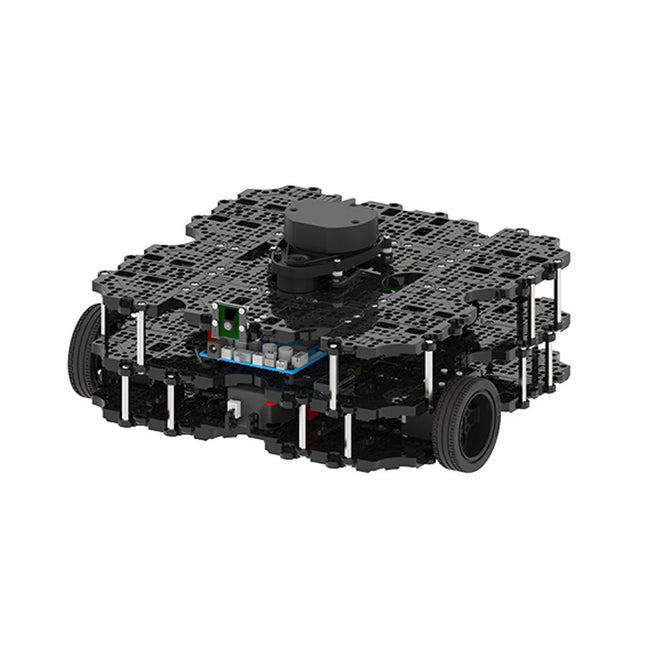
World’s Most Popular ROS PlatformTurtleBot is the most popular open source robot for education and research. The new generation TurtleBot3 is a small, low cost, fully programmable, ROS based mobile robot. It is intended to be used for education, research, hobby and product prototyping.Affordable CostTurtleBot was developed to meet the cost-conscious needs of schools, laboratories and companies. TurtleBot3 is the most affordable robot among the SLAM-able mobile robots equipped with a 360° Laser Distance Sensor LDS-01.ROS StandardThe TurtleBot brand is managed by Open Robotics, which develops and maintains ROS. Nowadays, ROS has become the go-to platform for all the roboticists around the world. TurtleBot can be integrated with existing ROS-based robot components, but TurtleBot3 can be an affordable platform for whom want to get started learning ROS.ExtensibilityTurtleBot3 encourages users to customize its mechanical structure with some alternative options: open source embedded board (as a control board), computer and sensors. TurtleBot3 Waffle Pi is a two-wheeled differential drive type platform but it is able to be structurally and mechanically customized in many ways: Cars, Bikes, Trailers and so on. Extend your ideas beyond imagination with various SBC, sensors and motors on a scalable structure.Modular Actuator for Mobile RobotTurtleBot3 is able to get a precise spatial data by using 2 DYNAMIXEL’s in the wheel joints. DYNAMIXEL XM series can be operated by one of 6 operating modes (XL series: 4 operating modes): Velocity control mode for wheels, Torque control mode or Position control mode for joint, etc. DYNAMIXEL can be used even to make a mobile manipulator which is light but can be precisely controlled with velocity, torque and position control. DYNAMIXEL is a core component that makes TurtleBot3 perfect. It is easy to assemble, maintain, replace and reconfigure.Open Control Board for ROSThe control board is open-sourced in hardware wise and in software wise for ROS communication. The open source control board OpenCR1.0 is powerful enough to control not only DYNAMIXEL’s but also ROBOTIS sensors that are frequently being used for basic recognition tasks in cost effective way. Various sensors such as Touch sensor, Infrared sensor, Color sensor and a handful more are available. The OpenCR1.0 has an IMU sensor inside the board so that it can enhance precise control for countless applications. The board has 3.3 V, 5 V, 12 V power supplies to reinforce the available computer device lineups.Open SourceThe hardware, firmware and software of TurtleBot3 are open source which means that users are welcomed to download, modify and share source codes. All components of TurtleBot3 are manufactured with injection molded plastic to achieve low cost, however, the 3D CAD data is also available for 3D printing.Specifications
Maximum translational velocity
0.26 m/s
Maximum rotational velocity
1.82 rad/s (104.27 deg/s)
Maximum payload
30 kg
Size (L x W x H)
281 x 306 x 141 mm
Weight (+ SBC + Battery + Sensors)
1.8 kg
Threshold of climbing
10 mm or lower
Expected operating time
2h
Expected charging time
2h 30m
SBC (Single Board Computers)
Raspberry Pi 4 (2 GB RAM)
MCU
32-bit ARM Cortex-M7 with FPU (216 MHz, 462 DMIPS)
Remote Controller
RC-100B + BT-410 Set (Bluetooth 4, BLE)
Actuator
XL430-W210
LDS (Laser Distance Sensor)
360 Laser Distance Sensor LDS-01 or LDS-02
Camera
Raspberry Pi Camera Module v2.1
IMU
Gyroscope 3 AxisAccelerometer 3 Axis
Power connectors
3.3 V/800 mA5 V/4 A12 V/1 A
Expansion pins
GPIO 18 pinsArduino 32 pin
Peripheral
3x UART, 1x CAN, 1x SPI, 1x I²C, 5x ADC, 4x 5-pin OLLO
DYNAMIXEL ports
3x RS485, 3x TTL
Audio
Several programmable beep sequences
Programmable LEDs
4x User LED
Status LEDs
1x Board status LED1x Arduino LED1x Power LED
Buttons and Switches
2x Push buttons, 1x Reset button, 2x Dip switch
Battery
Lithium polymer 11.1 V 1800 mAh / 19.98 Wh 5C
PC connection
USB
Firmware upgrade
via USB / via JTAG
Power adapter (SMPS)
Input: 100-240 VAC 50/60 Hz, 1.5 A @maxOutput: 12 VDC, 5 A
Downloads
ROS Robot Programming
GitHub
E-Manual
Community
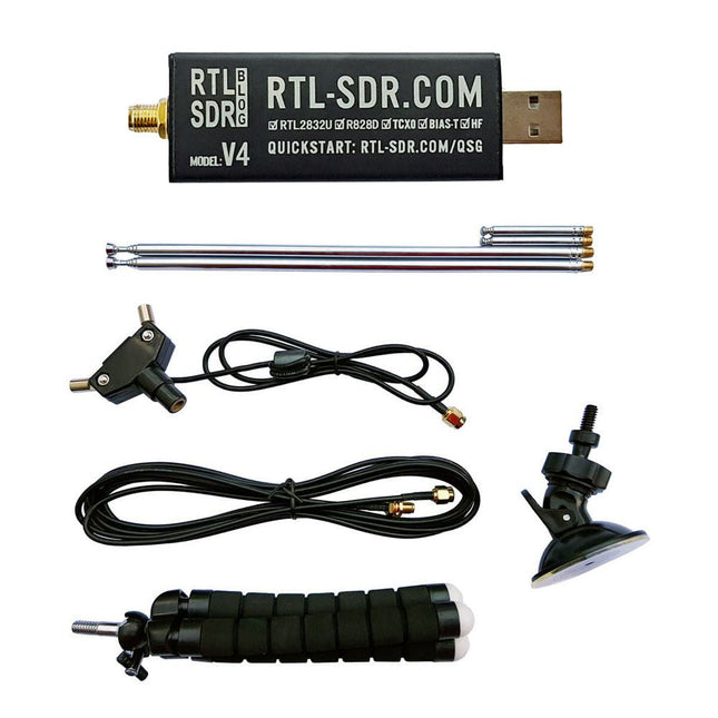
De RTL-SDR is een betaalbare dongle die kan worden gebruikt als een computer-ondersteunde radioscanner voor het ontvangen van live radiosignalen tussen 500 kHz en 1,75 GHz bij u in de buurt.
Deze RTL-SDR V4 heeft verschillende verbeteringen waaronder het gebruik van de R828D tunerchip, een triplex ingangsfilter, een notchfilter, verbeterde componenttoleranties, een 1 PPM temperatuur-gecompenseerde oscillator (TCXO), een SMA F-connector, aluminium behuizing met passieve koeling, bias T-circuit, verbeterde voeding en een ingebouwde HF upconverter.
RTL-SDR V4 wordt geleverd met een draagbare dipool antennekit. Het is een geweldig apparaat voor beginners omdat hij terrestrial en satellietontvangst mogelijk maakt, gemakkelijk buitenshuis kan worden gemonteerd, en geschikt is voor draagbaar en tijdelijk gebruik onderweg.
Kenmerken
Verbeterde HF-ontvangst: De V4 maakt gebruik van een ingebouwde upconverter in plaats van een direct sampling circuit. Dit betekent dat er geen gebruik meer hoeft te worden gemaakt wordt van de Nyquist-frequentie van rond de 14,4 MHz, wat een verbeterde gevoeligheid en een instelbare versterking op HF mogelijk maakt. Net als bij de V3 blijft het laagste afstembereik 500 kHz en kan bij een zeer sterk ontvangstsignaal nog steeds front-end verzwakking/filtering nodig zijn.
Verbeterde filtering: De V4 maakt gebruik van de R828D tunerchip die drie ingangen heeft. De SMA ingang is drievoudig uitgevoerd voor 3 banden: HF, VHF en UHF. Dit zorgt voor enige isolatie tussen de 3 banden, wat betekent dat out-of-band interferentie van sterke zenders minder snel verminderde gevoeligheid of spiegelsignalen kan veroorzaken.
Verbeterde filtering x2: Naast de triplex ingang kan ook de open drain pin op de R828D worden gebruikt. Hierop kunnen eenvoudige notch-filters worden aangesloten voor bekende banden qua interferentie, zoals de AM en FM omroepbanden en de DAB-banden. Deze dempen slechts met een paar dB maar kunnen nog steeds van nut zijn.
Verminderde faseruis op sterke signalen: Door een verbeterd ontwerp van de voeding is de faseruis als gevolg van ruis uit de voeding aanzienlijk verminderd.
Minder warmte: Een ander voordeel van de verbeterde voeding is een lager stroomverbruik en minder warmteontwikkeling in vergelijking met de V3.
Inbegrepen
1x RTL-SDR V4-dongle (R828D RTL2832U 1PPM TCXO SMA)
2x 23 cm tot 1 m telescoop antenne
2x 5 cm tot 13 cm telescoop antenne
1x Dipool antennevoet met 60 cm RG174
1x 3 m RG174 verlengkabel
1x Flexibele statiefbevestiging
1x Zuignapbevestiging
Downloads
Datasheet
User Guide
Quick Start Guide
SDR# User Guide
Dipole Antenna Guide
The short-wave technique has a very particular appeal: It can easily bridge long distances. By reflecting short-wave signals off the conductive layers of the ionosphere, they can be received in places beyond the horizon and therefore can reach anywhere on earth. Although technology is striving for ever higher frequencies, and radio is usually listened to on FM, DAB+, satellite or the Internet, modern means of transmission require extensive infrastructure and are extremely vulnerable. In the event of a global power outage, there is nothing more important than the short-wave. Amateur radio is not only a hobby, it’s also an emergency radio system!
Elektor’s SDR-Shield is a versatile shortwave receiver up to 30 MHz. Using an Arduino and the appropriate software, radio stations, morse signals, SSB stations, and digital signals can be received.
In this book, successful author and enthusiastic radio amateur, Burkhard Kainka describes the modern practice of software defined radio using the Elektor SDR Shield. He not only imparts a theoretical background but also explains numerous open source software tools.
Programming with GNU Radio
HackRF is an open-source hardware platform developed by Great Scott Gadgets and serves as a versatile front end for software-defined radio (SDR). With HackRF One and its successor, HackRF Pro, users can develop their own SDR applications, build powerful receivers and transmitters, and tackle demanding RF measurement tasks.
This book provides a practical introduction to the world of SDR. Step by step, the author shows how powerful SDR projects can be implemented with HackRF – from the fundamentals of RF technology to advanced applications using GNU Radio.
In addition to working with SDR Sharp (SDR#), RadioConda, and GNU Radio, the book also covers the fundamentals of modern digital signal processing. Numerous experiments and easy-to-follow practical examples guide readers through topics such as AM, FM, and SSB reception, digital filters, shortwave radio, amateur radio, signal generators, and custom RF projects up to 6 GHz.
Whether you are a maker, radio amateur, electronics enthusiast, or SDR beginner, this book provides solid knowledge, practical applications, and the motivation to creatively explore the possibilities of modern SDR technology.
De nRSP-ST is een op een netwerk aangesloten radio-ontvanger met algemene dekking voor frequenties van 1 kHz tot 2 GHz met een spectrumzichtbaarheid tot 10 MHz. De nRSP-ST is uw eigen persoonlijke, op afstand toegankelijke SDR die u ook kunt delen met een klein aantal vertrouwde vrienden of collega's.
De nRSP-ST komt tegemoet aan de behoeften van radioliefhebbers die een 'plug-and-play'-oplossing willen voor ontvangst op afstand. Naast dat we dit hebben bereikt, hebben we typische internetbandbreedtebeperkingen aangepakt door een nieuwe IQ Lite-modus te creëren, die op efficiënte wijze kanalen met IQ-gegevens levert. We introduceren ook de mogelijkheid om IQ-opnames op een externe locatie te beheren en op te slaan. De nRSP-ST is ideaal voor iedereen die een breedbandontvanger op afstand wil zonder computervaardigheden en urenlange insteltijd en doorlopend onderhoud op de externe locatie.
Kenmerken
"Plug and play" geïntegreerde, op een netwerk aangesloten ontvanger met algemene dekking:
Combineert een ontvanger, een hostcomputer en nog veel meer – alles in één doos!
Sluit de stroom aan en maak verbinding met internet (Ethernet of Wi-Fi) en de nRSP-ST is automatisch overal toegankelijk
Multi-platform SDRconnect-software ondersteunt lokale bediening of externe toegang op Windows-, MacOS- of Linux-platforms
De nRSP-ST & SDRconnect kan worden geconfigureerd voor de beschikbare netwerkbandbreedte:
In de Full IQ-modus biedt de nRSP-ST IQ-gegevensoverdracht van de zichtbare spectrumbandbreedte (bijvoorbeeld voor hogesnelheids-LAN of supersnelle internetverbinding)
In de IQ Lite-modus levert de nRSP-ST IQ-gegevens van kanalen tot 192 kHz breed (bijvoorbeeld voor digitale decodering door de klant)
In de Compact modus levert de nRSP-ST gecomprimeerde audio (ideaal voor langzamere internetverbindingen)
Ondersteunt meerdere clientverbindingen met een gelijktijdige combinatie van verbindingsmodi. Met een beheerderstool kunt u gebruikersnamen en time-outs toewijzen aan vertrouwde vrienden of collega's.
Alle modi ondersteunen visualisatie van een spectrumbandbreedte tot 10 MHz
Twee opties voor externe verbinding:
Gebruik een externe SDRconnect-client of
Gebruik de ingebouwde webserver voor externe toegang vanaf elk apparaat dat geschikt is voor internetten, inclusief Android-/iOS-tablets en -telefoons
De nRSP-ST biedt de mogelijkheid om IQ- en audiobestanden op te nemen op een NAS-apparaat (Network Attached Storage), indien beschikbaar op het LAN.
De 14-bits ADC volledig uitgeruste breedband SDR-ontvanger bestrijkt alle frequenties van 1 kHz via VLF, LF, MW, HF, VHF, UHF en L-band tot 2 GHz, zonder onderbrekingen
Bewaak op afstand tot 10 MHz spectrum per keer via een keuze uit 3 antennes
Flash kan worden geüpgraded voor toekomstige functieverbeteringen
Inbegrepen
1x nRSP-ST ontvanger
1x WLAN-antenne
1x Voeding
1x Manual
Downloads
Release notes
Software