Producten
-

Andonstar Andonstar AD409 Max-ES 10,1" HDMI Digitale Microscoop (incl. Endoscoop)
De Andonstar AD409 Max-ES heeft een hoogwaardige metalen lens en een uniek UV-filterontwerp. Het is gemaakt van hoogwaardige materialen van industriële kwaliteit en levert ongeëvenaarde precisie en duurzaamheid, waardoor een betrouwbare productervaring wordt gegarandeerd. Het UV-filter dat voor de metalen lens is geplaatst, blokkeert soldeerhitte, rook en stof, beschermt de lens en maakt hem perfect voor soldeer- en onderhoudsprofessionals. De AD409 Max-ES is voorzien van een extra groot Max-station (46 x 37 x 47,5 cm) en een geavanceerde gereedschapsset, waardoor het soldeerstationoppervlak met 370% wordt uitgebreid. Deze upgrade voldoet aan de eisen van professionele soldeerwerkzaamheden en biedt voldoende werkruimte voor grotere projecten. De gebruiksvriendelijke gereedschapshouder houdt gereedschap binnen handbereik en zorgt ervoor dat ze altijd toegankelijk zijn. Bovendien vereenvoudigen de soldeerhulphanden met draaibare klemmen soldeer- en reparatietaken, waardoor de efficiëntie en het gemak worden vergroot. De endoscoop biedt een rondom zicht van 360°. Dit maakt duidelijke observatie van componenten van alle kanten en in leidingen mogelijk, waardoor blinde hoeken worden geëlimineerd en grondige inspecties worden gegarandeerd. Kenmerken Hoogwaardige metalen lens en uniek UV-filterontwerp Nieuw Max-station Eenvoudig te gebruiken gereedschapshouder en helpende handen bij het solderen Microscoop met endoscoop rondom zicht 360° Professionele HDMI digitale microscoop ondersteunt meerdere uitvoermethoden In 8 niveaus verstelbare LED's Handige draadloze afstandsbediening Specificaties Schermgrootte 10,1 inch (1200x800) Beeldsensor 4 MP Video uitgang UHD 2880x2160 (24 fps)FHD 1920x1080 (60 fps/30 fps)HD 1280x720 (120 fps) Video formaat MP4 Vergroting Tot 300 keer (27 inch HDMI-monitor) Foto resolutie Max. 24 MP (5600x4200) Foto formaat JPG Focus afstand Min. 5 cm Frame rate Max. 120fps Video interface HDMI Opslag MicroSD-kaart (tot 64 GB) PC-ondersteuning Windows, PC-software met metingen Mobiele telefoon, tablet en terminal ondersteuning Ondersteuning WiFi-verbinding en metingen Voeding 5 V DC Verlichting 2 LED's op de standaard Endoscoop Ja Afmetingen standaard 46 x 37 x 47,5 cm Inbegrepen 1x Andonstar AD409 Max-ES Digitale Microscoop 1x Endoscoop 1x Standaard met 2 LED's 1x UV-filter (reeds gemonteerd in de lens) 1x Soldeermat 1x Drager 1x Kolom 1x Gereedschapshouder 1x Solderende helpende handen 1x Voedingsadapter 1x Voedingskabel 1x HDMI-kabel 1x USB-kabel 1x IR-afstandsbediening 1x Manual Downloads Manual Software
€ 399,00€ 349,00
Beste prijs
-

Andonstar Andonstar AD409 Pro-ES 10,1" HDMI Digitale Microscoop (incl. Endoscoop)
De Andonstar AD409 Pro-ES is een digitale microscoop, met een extra hoge standaard, die tevens is uitgerust met een endoscoop. De microscoop maakt een duidelijke observatie mogelijk van de zijkanten van componenten, de binnenkant van leidingen, enz., waardoor 360° observatie zonder dode hoeken mogelijk is. De microscoop heeft ook een afstandsbediening waarmee u eenvoudig kunt schakelen tussen de volgende schermmodi: twee lenzen, microscoop en endoscoop. Kenmerken Hoogwaardige metalen lens met focus ring Professionele HDMI digitale microscoop die meerdere uitvoermethoden ondersteunt Soldeermicroscoop met Pro Metal Stand Uniek UV-filter ontwerp Instelbare LED-verlichting met 8 niveaus Handige draadloze afstandsbediening Professionele meetsoftware Specificaties Schermgrootte 10,1 inch (25,7 cm) Beeldsensor 4 MP Video uitgang UHD 2880x2160 (24 fps)FHD 1920x1080 (60 fps/30 fps)HD 1280x720 (120 fps) Video formaat MP4 Vergroting Tot 300 keer (27 inch HDMI-monitor) Foto resolutie Max. 12 MP (4032x3024) Foto formaat JPG Focus afstand Min. 5 cm Frame rate Max. 120fps Video interface HDMI Opslag MicroSD-kaart (tot 64 GB) PC-ondersteuning Windows, PC-software met metingen Mobiele telefoon, tablet en terminal ondersteuning Ondersteuning WiFi-verbinding en metingen Voeding 5 V DC Verlichting 2 LED's op de standaard Endoscoop Ja Afmetingen standaard 18 x 20 x 32 cm Inbegrepen 1x Andonstar AD409 Pro-ES Digital Microscope 1x Endoscoop 1x Metalen standaard met 2 LED's 1x UV-filter (reeds gemonteerd in de lens) 1x IR-afstandsbediening 1x Switch kabel 1x Voedingsadapter 1x Instelsleutel 2x Metalen clips 1x HDMI-kabel 1x Gebruikershandleiding Downloads Manual Software
€ 349,00€ 299,00
Beste prijs
-

Andonstar Andonstar ADSM302 5" HDMI Digitale Microscoop
De Andonstar ADSM302 is een veelzijdige digitale microscoop met geïntegreerd 5-inch LCD-scherm en HDMI-uitgang voor haarscherpe beelden in Full HD (1080p). Met een 3-megapixelsensor, een vergroting tot ~560x en twee instelbare ledlampjes maakt hij de kleinste details zichtbaar – ideaal voor het inspecteren van printplaten, soldeerwerkzaamheden, het analyseren van sieraden of insecten. Kenmerken 5" adjustable LCD monitor with adjustable tilt angle High resolution video & photo capture Wide table with comfortable headroom Heavy-weight stable metal stand Tall lifting stand (26 cm) Smooth adjustment wheels for focus and height Buttons on the monitor + remote control AV, USB, HDMI outputs SD card storage <32 GB Specificaties Image sensor 3 Megapixels HD Sensor Video output 1080p Full HD (via HDMI)720p (via PC) Video format Real time play via HDMI w/o recordingMJPEG recording via PC/Mac Software Magnification Up to 560 times (HDMI monitor 22') Photo resolution 12M (see pixel formats in following table) Photo format JPEG Focus range 5 to 22 cm Frame rate Up to 30 f/s under 600 Lux Brightness Video-output interface HDMI/AV Storage microSD card, up to 32 GB PC support Windows XP/7/8/10PC software with measurementMacOS successfully tested under OSX with OBSsee video below Power source 5 V DC Light source 2x LED with the stand Screen size 5 inch (12.7 cm) Stand size 20 x 12 x 26.5 cm Resolutie Captured Photos 4032 x 3024 3648 x 2736 3264 x 2448 2592 x 1944 2048 x 1536 640 x 480 1920 x 1080 1280 x 960 1280 x 720* Videos 1920 x 1080 640 x 480* * (USB with software) Inbegrepen 1x Andonstar ADSM302 digital microscope 1x Metal stand with 2 LEDs 1x USB cable 1x HDMI cable 1x Adapter 1x AI remote 1x Instructions Downloads Manual Software
€ 199,00
-

Andonstar Andonstar Max Station Upgrade-set voor AD409-modellen
Upgrade je Andonstar AD409, AD409 Pro of AD409 Pro-ES naar het Max-model met deze uitbreidingsset. Het nieuw ontworpen, oversized Max-station biedt voldoende werkruimte, waardoor het perfect is voor grotere projecten en ideaal voor professionele soldeertaken. Inbegrepen 1x Standaard met 2 LED's 1x Reparatiemat 1x Drager 1x Kolom 1x Gereedschapshouder 1x Solderende helpende handen
€ 60,00
-

Elektor Digital Android, Apps programmeren stap voor stap (E-book)
Steeds vaker komen we op smartphones en tablet-computers het besturingssysteem Android tegen. Het aantal toepassingsprogramma's - de zogenaamde applicaties of kortweg apps - waarmee de apparaten individueel aan de voorkeuren en wensen van de gebruiker kunnen worden aangepast, neemt van dag tot dag toe. En de steeds betere technische uitvoering en uitrusting van de apparaten maken het nu mogelijk toepassingen te 'draaien' waarvoor een paar jaar geleden nog een desktop-PC of speciale hardware vereist was. Inmiddels kan elke smartphone de exacte (geografische) positie bepalen, video's opnemen - en nog veel meer. Maar bij het individualiseren van onze smartphone hoeven we ons niet te beperken tot kant-en-klare applicaties! Het is namelijk helemaal niet zo moeilijk om zelf Android-apparaten te programmeren en eigen apps te schrijven. Dit boek vormt een inleiding tot het programmeren van apps voor Android-apparaten. De werking van het Android-systeem wordt op begrijpelijke manier uitgelegd en we zien stap voor stap hoe applicaties kunnen worden geprogrammeerd. Aan de hand van een groot aantal voorbeelden worden allerlei toepassingsmogelijkheden getoond. Het scala loopt van eenvoudige rekenprogramma's via het uitlezen van sensoren en GPS-data tot het programmeren van applicaties voor internetcommunicatie. Naast het schrijven van applicaties in de programmeertaal Java wordt in dit boek ook besproken hoe apps met behulp van Javascript of PHP-scripts kunnen worden geprogrammeerd.
€ 29,95
Leden: € 26,96
-

Elektor Publishing Apple Macintosh
20+ Macintosh Models, from 1984 to Today (History, Engineering, and Restoration) Apple is not like any other company. More than anyone else, it transformed technology into something people could desire, love, and even identify with—much like a luxury brand. Users were not only buying a tool; they were buying a vision, a way of life. At the center of this transformation stands the Macintosh. First introduced in 1984, it was radically different from everything before. With its graphical interface and mouse, it made computing approachable, even friendly. What now feels obvious—clicking on icons, dragging files, pointing instead of typing commands—was revolutionary at the time. The Macintosh not only changed the way people related to technology. The Macintosh forced the entire industry to rethink the way we use computers. This book tells that story through some of the most significant Macintosh models. Each one is presented not only in words but also in images, because these computers are more than technology—they are design icons, symbols of a unique vision. History, technical detail, and photography come together here, aiming to show each Macintosh as it truly deserves to be seen.
€ 79,95
Leden: € 71,96
-

Elektor Digital Arduino & Co – Measure, Control, and Hack (E-book)
Clever Tricks with ATmega328 Pro Mini Boards With a simple Pro Mini board and a few other components, projects that 20 or 30 years ago were unthinkable (or would have cost a small fortune) are realized easily and affordably in this book: From simple LED effects to a full battery charging and testing station that will put a rechargeable through its paces, there’s something for everyone. All the projects are based on the ATmega328 microcontroller, which offers endless measuring, switching, and control options with its 20 input and output lines. For example, with a 7-segment display and a few resistors, you can build a voltmeter or an NTC-based thermometer. The Arduino platform offers the perfect development environment for programming this range of boards. Besides these very practical projects, the book also provides the necessary knowledge for you to create projects based on your own ideas. How to measure, and what? Which transistor is suitable for switching a certain load? When is it better to use an IC? How do you switch mains voltage? Even LilyPad-based battery-operated projects are discussed in detail, as well as many different motors, from simple DC motors to stepper motors. Sensors are another exciting topic: For example, a simple infrared receiver that can give disused remote controls a new lease on life controlling your home, and a tiny component that can actually measure the difference in air pressure between floor and table height!
€ 32,95
Leden: € 29,66
-

Elektor Academy Pro Arduino (programmeercursus)
Deze complete microcontroller-programmeercursus op basis van de Arduino Uno bevat een leerboek, een componentenkit, praktische projecten en een uitgebreide online cursus met simulaties. Ideaal om embedded systems stap voor stap te leren programmeren met Arduino via een praktische hands-on aanpak. Een praktische introductie tot embedded systems met de Arduino Uno Deze cursus is ontworpen voor beginners in embedded systems die op zoek zijn naar een gestructureerde en voorbeeldgerichte start. Een kit met LED’s en weerstanden, schakelaars, sensoren en actuatoren, displays, een breadboard en draden is inbegrepen. Deze worden in de cursus gebruikt om voorbeeldtoepassingen te demonstreren. Er is geen voorkennis van Arduino of embedded ontwikkeling vereist. Elke sectie bevat praktische voorbeelden en mini-projecten om belangrijke concepten te versterken en verdere verkenning te stimuleren. Aan het einde van de cursus kunt u niet alleen de voorbeelden reproduceren, maar ook uitbreiden met uw eigen ideeën en toepassingen. Wat leert u? Microcontrollerprogrammering met Arduino met behulp van het Uno R3 board Werken met digitale I/O, knoppen en encoders uitlezen, LED’s en relais aansturen Analoge ingangen, spanningen en sensoren uitlezen Genereren van analoge uitgangssignalen en PWM Gebruik van seriële communicatie zoals UART, I²C en SPI om displays aan te sturen en digitale sensoren en SD-kaarten uit te lezen Tijdbeheer Werken met interrupts Realtime sensorinput en besturing via knoppen, LED’s en displays Aansturen van actuatoren zoals relais en servomotoren Voor wie is dit? Studenten en zelflerenden die embedded systems willen ontdekken Makers en IoT-enthousiastelingen die hun hardwarevaardigheden willen verbeteren Docenten en trainers die kant-en-klaar lesmateriaal zoeken Wat zit er in de doos? Toegang tot de volledige cursus op het Elektor Academy Pro leerplatform Uno R3 microcontrollerboard + USB-kabel Boek: Programming Microcontrollers in C/C++ Using Arduino Downloadbare projectbestanden voor elke module Componentenkit: 2× LED, rood, 5 mm LED, groen, 5 mm 3× weerstand, 470 Ω, 0,25 W LDR Potentiometer, 10 kΩ, lineair Drukknop Rotary encoder module Relaismodule DHT22 temperatuur- en vochtigheidssensor TM1637-compatibel 4-digit 7-segment display MPU-6050 IMU met headers SSD1306-compatibel I²C OLED display Micro SD-kaartadapter met header Buzzer SG90 micro servo ILI9341-compatibel SPI 240×320 TFT display 20× jumper wires Breadboard Alle programmeercursussen (en verschillen in inhoud) Cursus Arduino Raspberry Pi Pico with Arduino C/C++ ESP32 with Arduino C/C++ Raspberry Pi Pico with MicroPython ESP32 with MicroPython Online cursus Access to Arduino Course Access to Pico with Arduino C/C++ Course Access to ESP32 with Arduino C/C++ Course Access to Pico with MicroPython Course Access to ESP32 with MicroPython Course Board Uno R3 Raspberry Pi Pico ESP32 Raspberry Pi Pico ESP32 Boek Programming Microcontrollers in C/C++ Using Arduino Programming Microcontrollers in C/C++ Using Arduino Programming Microcontrollers in C/C++ Using Arduino Programming Microcontrollers in MicroPython Programming Microcontrollers in MicroPython Kit 40-delige componenten-kit 40-delige componenten-kit 40-delige componenten-kit 40-delige componenten-kit 40-delige componenten-kit
€ 69,95
Leden: € 62,96
-
Elektor Digital Arduino 8-bit Sound Generation (E-book)
Arduinonext is an initiative powered by an electronics and microcontrollers specialist team aiming to help all those who are entering in the technology world, using the well-known Arduino platform to take the next step in electronics. We strive to bring you the necessary knowledge and experience for developing your own electronics applications; interacting with environment; measuring physical parameters; processing them and performing the necessary control actions. This is the first title in the 'Hands-On' series in which Arduino platform co-founder, David Cuartielles, introduces board programming, and demonstrates the making of an 8-bit Sound Generator.
€ 7,95
Leden: € 7,16
-
Elektor Digital Elektor Select: Arduino Compilatie (PDF)
Dit 216 pagina's tellende e-book staat boordevol Arduino-ideeën, uitleg, tips, diagrammen, programma's, PCB layouts en meer. Genoeg voor dagen vol informatief, inspirerend en stimulerend leesplezier! Opgemaakt als PDF bevat dit digitale document een inhoudsopgave inclusief links naar elk project, zo dat u gemakkelijk komt waar u wilt zijn. Dit biedt u de mogelijkheid om tussen projecten te wisselen en degene die u het meeste boeien snel en gemakkelijk te vinden.
€ 9,95
Leden: € 8,96
-
Elektor Publishing Arduino for Radio Amateur Applications
Program and build Arduino-based ham station utilities, tools, and instruments In addition to a detailed introduction to the exciting world of the Arduino microcontroller and its many variants, this book introduces you to the shields, modules, and components you can connect to the Arduino. Many of these components are discussed in detail and used in the projects included in this book to help you understand how these components can be incorporated into your own Arduino projects. Emphasis has been placed on designing and creating a wide range of amateur radio-related projects that can easily be built in just a few days. This book is written for ham radio operators and Arduino enthusiasts of all skill levels, and includes discussions about the tools, construction methods, and troubleshooting techniques used in creating amateur radio-related Arduino projects. The book teaches you how to create feature-rich Arduino-based projects, with the goal of helping you to advance beyond this book, and design and build your own ham radio Arduino projects. In addition, this book describes in detail the design, construction, programming, and operation of the following projects: CW Beacon and Foxhunt Keyer Mini Weather Station RF Probe with LED Bar Graph DTMF Tone Encoder DTMF Tone Decoder Waveform Generator Auto Power On/Off Bluetooth CW Keyer Station Power Monitor AC Current Monitor This book assumes a basic knowledge of electronics and circuit construction. Basic knowledge of how to program the Arduino using its IDE will also be beneficial.
€ 39,95
Leden: € 35,96
-

Elektor Digital Arduino for Radio Amateur Applications (E-book)
Program and build Arduino-based ham station utilities, tools, and instruments In addition to a detailed introduction to the exciting world of the Arduino microcontroller and its many variants, this book introduces you to the shields, modules, and components you can connect to the Arduino. Many of these components are discussed in detail and used in the projects included in this book to help you understand how these components can be incorporated into your own Arduino projects. Emphasis has been placed on designing and creating a wide range of amateur radio-related projects that can easily be built in just a few days. This book is written for ham radio operators and Arduino enthusiasts of all skill levels, and includes discussions about the tools, construction methods, and troubleshooting techniques used in creating amateur radio-related Arduino projects. The book teaches you how to create feature-rich Arduino-based projects, with the goal of helping you to advance beyond this book, and design and build your own ham radio Arduino projects. In addition, this book describes in detail the design, construction, programming, and operation of the following projects: CW Beacon and Foxhunt Keyer Mini Weather Station RF Probe with LED Bar Graph DTMF Tone Encoder DTMF Tone Decoder Waveform Generator Auto Power On/Off Bluetooth CW Keyer Station Power Monitor AC Current Monitor This book assumes a basic knowledge of electronics and circuit construction. Basic knowledge of how to program the Arduino using its IDE will also be beneficial.
€ 32,95
Leden: € 29,66
-

Elektor Digital Arduino in Control (3e versie) E-book
Physical Computing met het Arduino-platform Dit leerboek over het Arduino-platform is uniek en brengt u stap voor stap van beginner tot gevorderde Arduino-gebruiker. Er wordt duidelijk in uitgelegd waarom en waardoor toepassingen werken, ondersteund door gedetailleerde afbeeldingen in kleur. Er is slechts een geringe elektronische basiskennis vereist, omdat de benodigde hardware uitgebreid wordt besproken. Het laatste gedeelte van dit boek bevat een degelijke theoretische verdieping, zodat u een krachtig naslagwerk achter de hand houdt. Er bestond in het Nederlands nog geen lesboek over dit platform. De didactische opbouw is zodanig dat de vereiste abstracte kennis wordt uitgelegd aan de hand van toepasbare en actuele praktijkvoorbeelden. De meeste toepassingen zijn gericht op ‘physical computing’, dat is de interactie tussen sensoren, actoren, elektronica en software. Hierdoor is het boek ook geschikt voor technisch beroepsonderwijs, o.a. voor de richting mechatronica. De opbouw van het boek is als volgt: Algemene introductie microcontrollers. Informatie over het Arduino-platform. Oefeningen met uitleg aan de hand van 21 voorbeelden. Praktijkvoorbeelden met uitleg aan de hand van 5 voorbeelden. Theoretische verdieping van de software en hardware. Praktische elektronicaschema´s. Alle software-voorbeelden in het boek zijn als download beschikbaar.
€ 34,95
Leden: € 31,46
-
Elektor Digital Arduino ontdekken in 45 Elektronica Projecten (E-book)
In dit boek worden een serie spannende en leuke projecten voor de Arduino behandeld, zoals een stil alarm, mensensensor, lichtmeter, besturing van een motor, internet en draadloze bediening (via een radioverbinding). In tegenstelling tot veel gratis projecten op internet zijn de projecten in dit boek in de praktijk getest, en werken gegarandeerd! U kunt dit boek gebruiken als projectenboek, en de 45 projecten nabouwen en in de praktijk inzetten. Door de duidelijke uitleg, schema's en zelfs foto's van de opstelling op is het nabouwen een erg leuke bezigheid. De foto's zijn gemaakt van een werkende opstelling, dus u weet zeker dat ze kloppen. U kunt de projecten in dit boek ook met elkaar combineren om zo uw eigen projecten te maken. Per project wordt duidelijk uitgelegd waarom het project op die manier is uitgevoerd. Al doende leert u veel over het project en de gebruikte onderdelen, en kunt u het project zelf aanpassen en uitbreiden naar uw eigen wensen. Daarnaast is het boek ook als naslagwerk inzetbaar. Via de index vindt u gemakkelijk projecten die als voorbeeld voor het gebruik van C++ opdrachten en Arduino-functionaliteit kunnen dienen. Zelfs als u alle projecten gemaakt hebt zal dit boek om die reden nog lang een plekje naast uw PC behouden.
€ 24,95
Leden: € 22,46
-
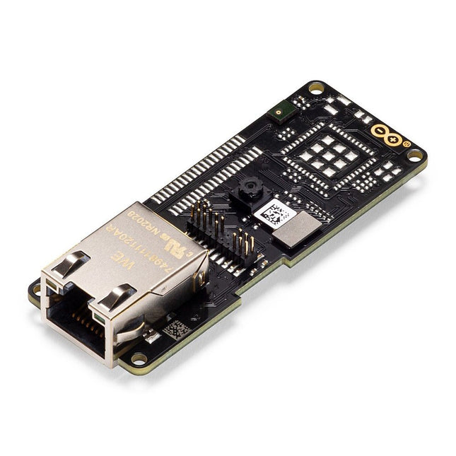
Arduino Arduino Portenta Vision Shield (Ethernet)
Features 324x324 pixels camerasensor: gebruik een van de kernen in Portenta om beeldherkenningsalgoritmes uit te voeren met de OpenMV for Arduino editor 100 Mbps Ethernet connector: verbind uw Portenta H7 met het bekabelde Internet 2 onboard microfoons voor richtingsgevoelige geluidsdetectie: vang en analyseer geluid in real-time JTAG connector: voer low-level debugging uit van uw Portenta bord of speciale firmware updates met behulp van een externe programmer SD-Card aansluiting: sla uw vastgelegde gegevens op de kaart op, of lees configuratiebestanden Het Vision Shield is ontworpen om bovenop de Arduino Portenta familie te passen. De Portenta boards zijn voorzien van multicore 32-bit ARM® Cortex™ processoren die draaien op honderden megahertz, met megabytes aan programmageheugen en RAM. Portenta boards worden geleverd met WiFi en Bluetooth.Embedded computer vision gemakkelijk gemaaktArduino heeft samengewerkt met OpenMV om u een gratis licentie voor de OpenMV IDE aan te bieden, een eenvoudige manier om computervisie te gebruiken met MicroPython als programmeerparadigma. Download de OpenMV voor Arduino Editor van onze professionele tutorials site en blader door de voorbeelden die we voor u hebben voorbereid in de OpenMV IDE. Bedrijven over de hele wereld bouwen al hun commerciële producten op basis van deze eenvoudig-maar-krachtige benadering voor het detecteren, filteren en classificeren van afbeeldingen, QR-codes, en anderen. Debugging met professioneel gereedschapSluit uw Portenta H7 aan op een professionele debugger via de JTAG connector. Gebruik professionele software tools zoals die van Lauterbach of Segger bovenop uw board om uw code stap voor stap te debuggen. Het Vision Shield maakt de benodigde pinnen vrij voor het aansluiten van uw externe JTAG. Camera Himax HM-01B0 cameramodule Resolutie 320 x 320 actieve pixel resolutie met ondersteuning voor QVGA beeldsensor Hoge gevoeligheid 3.6? BrightSense™ pixel technologie Microfoon 2 x MP34DT05 Lengte 66 mm Breedte 25 mm Gewicht 11 gr Voor meer informatie, bekijk de tutorials die door Arduino hier.
€ 69,95€ 19,95
Beste prijs
-

Elektor Bundles Arduino UNO Q (Bundel)
Deze bundel bevat de Arduino UNO Q (2 GB) en het nieuwe boek "Arduino UNO Q and AI". De Arduino UNO Q is het eerste UNO-bord met een hybride dual-brain-architectuur, waarbij een krachtige Linux-processor wordt gecombineerd met een realtime-microcontroller – zo worden geavanceerde rekenkracht en nauwkeurige besturing op één bord samengebracht. Aangedreven door een Qualcomm Dragonwing QRB2210 MPU met Debian Linux en een STM32U585 MCU voor realtime taken, is de UNO Q gebouwd voor toepassingen van de volgende generatie. Van Edge Computing en AI tot robotica en automatisering, het levert hoge prestaties zonder in te boeten aan gebruiksgemak. Sluit gewoon uw randapparatuur aan en ga aan de slag – er is geen extra hardware nodig. Kenmerken Dual-core architectuur: Linux MPU + realtime MCU Qualcomm Dragonwing QRB2210 met ondersteuning voor Debian Linux STM32U585-microcontroller voor deterministische besturing Voert Arduino-schetsen uit via Zephyr OS Ideaal voor AI, IoT, robotica en industriële projecten Specificaties Microprocessor (MPU) Qualcomm Dragonwing QRB2210:Quad-core Arm Cortex-A53 @ 2,0 GHzAdreno GPU 3D-grafische accelerator2× ISP (13 MP + 13 MP of 25 MP) @ 30 fps Microcontroller (MCU) STM32U585Arm Cortex-M33 tot 160 MHz2 MB flashgeheugen786 KB SRAM RAM 2 GB LPDDR4 Voeding Via USB-C-connector 5 V max bij 3 AIngangsspanning (VIN): 7-24 V Geheugen 16 GB eMMC USB 1× USB-C-poort met host/device-rolschakeling, stroomrolschakeling en video-uitgang Connectiviteit Wi-Fi 5 (2,4/5 GHz) met ingebouwde antenneBluetooth 5.1 met ingebouwde antenne antenne Interfaces I²C/I³CSPIPWMCANUARTPSSIGPIOJTAGADC Video Ondersteuning voor video-uitvoer via USB-CMIPI DSI-pinnen op JMEDIA-header Extra 4× RGB-LED's die door de gebruiker kunnen worden aangestuurd8×13 blauwe LED-matrix1× Qwiic-connector, spanning 3V3, I²C1× drukknop voor de gebruikerJCTL: MPU Remote Debug connector Audio Microfoon IN / Hoofdtelefoon UIT / Lijn UIT op JMISC MPU-besturingssysteem Linux Debian OS met upstream-ondersteuning Realtime-besturingssysteem Arduino Core op Zephyr OS Containerisatie Ondersteuning voor Docker en Docker Compose Ondersteunde besturingssystemen voor Arduino App Lab Windows: Windows 10 of later (64-bit)macOS: macOS 11 of later (64-bit)Linux: Ubuntu 22.04 of later en Debian Trixie (64-bit) Afmetingen 68,85 × 53,34 mm (UNO-vormfactor) Downloads Datasheet User Manual Pinout Schematics Boek: Arduino UNO Q and AI – Learn to Build Intelligent Embedded Systems Bouw slimmere embedded systemen met de Arduino UNO Q. Dit boek biedt u de tools, kennis en het vertrouwen om ideeën om te zetten in intelligente, werkende oplossingen met het Arduino UNO Q-platform. Ontdek hoe u intelligente embedded systemen kunt bouwen met de Arduino UNO Q en AI. Ontgrendel het volledige potentieel van de Arduino UNO Q, een next-generation platform dat de realtime kracht van de STM32U585-microcontroller combineert met de flexibiliteit van een Qualcomm Dragonwing QRB2210-microprocessor. Leer hoe u snel realistische toepassingen kunt prototypen met de Arduino IDE voor low-level embedded besturing en Python in Arduino App Lab voor high-level ontwikkeling. Bouw vertrouwen op met praktische projecten die u stap voor stap begeleiden van basisfunctionaliteiten tot volledig werkende systemen. Verken kant-en-klare, op AI gebaseerde Arduino App Lab-voorbeelden en ontdek hoe deze uw ontwikkeling kunnen versnellen en de time-to-market verkorten. Zet uw eerste stappen in de wereld van Edge AI met een duidelijke en praktische introductie tot Edge Impulse Studio – geen eerdere AI-ervaring vereist. Volg een volledige, realistische workflow om een Keyword Spotting AI-toepassing te ontwikkelen, inclusief dataverzameling, modeltraining, optimalisatie en on-device inferentie met behulp van Edge Impulse Studio. Overbrug de kloof tussen embedded systemen en machine learning en leer hoe u intelligentie direct op uw hardware kunt implementeren. Perfect voor embedded engineers, docenten, studenten en makers die voorop willen blijven lopen in AI-gedreven productontwikkeling. Deze bundel bevat: Arduino UNO Q (2 GB) (t.w.v. € 50) Boek: Arduino UNO Q and AI (t.w.v. € 35)
€ 84,95€ 74,95
Beste prijs
-

Elektor Publishing Arduino UNO Q and AI
Learn to Build Intelligent Embedded Systems Build smarter embedded systems with Arduino UNO Q. This book gives you the tools, knowledge, and confidence to turn ideas into intelligent, working solutions using the Arduino UNO Q platform. Discover how to build intelligent embedded systems with the Arduino UNO Q and AI. Unlock the full potential of the Arduino UNO Q, a next-generation platform that combines the real-time power of the STM32U585 microcontroller with the flexibility of a Qualcomm Dragonwing QRB2210 microprocessor. Learn how to rapidly prototype real-world applications using the Arduino IDE for low-level embedded control and Python in Arduino App Lab for high-level development. Build confidence through hands-on projects that guide you step by step from basic board features to complete working systems. Explore ready-to-use, AI based Arduino App Lab examples and see how they can jump-start your development and reduce time to deployment. Step into the world of Edge AI with a clear, practical introduction to Edge Impulse Studio—no prior AI experience required. Follow a complete, real-world workflow to create a Keyword Spotting AI application, covering data collection, model training, optimization, and on-device inference using the Edge Impulse Studio. Bridge the gap between embedded systems and machine learning and learn how to bring intelligence directly onto your hardware. Perfect for embedded engineers, educators, students, and makers looking to stay ahead in AI-enabled product development.
€ 34,95
Leden: € 31,46
-

Elektor Digital Arduino UNO Q and AI (E-book)
Learn to Build Intelligent Embedded Systems Build smarter embedded systems with Arduino UNO Q. This book gives you the tools, knowledge, and confidence to turn ideas into intelligent, working solutions using the Arduino UNO Q platform. Discover how to build intelligent embedded systems with the Arduino UNO Q and AI. Unlock the full potential of the Arduino UNO Q, a next-generation platform that combines the real-time power of the STM32U585 microcontroller with the flexibility of a Qualcomm Dragonwing QRB2210 microprocessor. Learn how to rapidly prototype real-world applications using the Arduino IDE for low-level embedded control and Python in Arduino App Lab for high-level development. Build confidence through hands-on projects that guide you step by step from basic board features to complete working systems. Explore ready-to-use, AI based Arduino App Lab examples and see how they can jump-start your development and reduce time to deployment. Step into the world of Edge AI with a clear, practical introduction to Edge Impulse Studio—no prior AI experience required. Follow a complete, real-world workflow to create a Keyword Spotting AI application, covering data collection, model training, optimization, and on-device inference using the Edge Impulse Studio. Bridge the gap between embedded systems and machine learning and learn how to bring intelligence directly onto your hardware. Perfect for embedded engineers, educators, students, and makers looking to stay ahead in AI-enabled product development.
€ 29,95
Leden: € 26,96
-

Elektor Bundles Arduino Uno R4 WiFi (Bundel)
Boek: Mastering the Arduino Uno R4 Gebaseerd op de voordelige 8-bits ATmega328P-processor, is het Arduino Uno R3-bord waarschijnlijk het populairste lid van de Arduino-familie geworden, en dit werkpaard is al vele jaren bij ons. Elf jaar later werd de langverwachte opvolger, de Arduino Uno R4, uitgebracht. Deze is gebouwd rond een 48 MHz, 32-bits Arm Cortex-M4 microcontroller en biedt aanzienlijk uitgebreider SRAM- en Flash-geheugen. Daarnaast zijn een nauwkeurigere ADC en een nieuwe DAC aan het ontwerp toegevoegd. Het Uno R4-bord ondersteunt ook de CAN-bus met een interface. Er zijn twee versies van het bord beschikbaar: Uno R4 Minima en Uno R4 WiFi. Dit boek gaat over het gebruik van deze nieuwe borden om veel verschillende en interessante projecten te ontwikkelen met slechts een handvol onderdelen en externe modules. Alle projecten die in het boek worden beschreven, zijn volledig getest op de Uno R4 Minima of de Uno R4 WiFi-kaart, afhankelijk van het type. De projectonderwerpen omvatten het uitlezen, besturen en aansturen van veel componenten en modules in de kit, evenals op de betreffende Uno R4-kaart, waaronder... LED's Weergaven met 7 segmenten (met timer-onderbrekingen) LCD's Sensoren RFID-lezer 4×4 toetsenbord Realtime klok (RTC) Joystick 8×8 LED-matrix Motoren DAC (digitaal-naar-analoog-omzetter) LED-matrix WiFi-connectiviteit Seriële UART CAN-bus Infraroodcontroller en ontvanger Simulatoren ... dit alles op creatieve en educatieve wijze, waarbij de werking van het project en de bijbehorende software tot in detail worden uitgelegd. Arduino Uno R4 WiFi De Arduino Uno R4 wordt aangedreven door de Renesas RA4M1 32-bits ARM Cortex-M4-processor, wat zorgt voor een aanzienlijke verbetering in rekenkracht, geheugen en functionaliteit. De wifi-versie wordt geleverd met een ESP32-S3 wifi-module naast de RA4M1, waardoor de creatieve mogelijkheden voor makers en ingenieurs worden uitgebreid. De Arduino Uno R4 werkt op 48 MHz, een verdrievoudiging ten opzichte van de populaire Uno R3. Daarnaast is het SRAM-geheugen geüpgraded van 2 kB naar 32 kB en het flashgeheugen van 32 kB naar 256 kB om complexere projecten te ondersteunen. Naar aanleiding van feedback van de community is de USB-poort nu een USB-C-poort en is de maximale voedingsspanning verhoogd naar 24 V met een verbeterd thermisch ontwerp. Het bord bevat een CAN-bus en een SPI-poort, waardoor gebruikers minder bedrading nodig hebben en parallelle taken kunnen uitvoeren door meerdere shields aan te sluiten. Er is ook een 12-bits analoge DAC op het bord aanwezig. Specificaties Microcontroller Renesas RA4M1 (ARM Cortex-M4) USB USB-C Programmeerpoort Pinnen Digitale I/O-pinnen 14 Pinnen Analoge ingangspinnen 6 DAC 1 RTC 1 PWM-pinnen 6 Communicatie UART 1x I²C 1x SPI 1x Qwiic I²C-connector 1x CAN 1x CAN-bus Voeding Bedrijfsspanning circuit 5 V Ingangsspanning (VIN) 6-24 V Gelijkstroom per I/O-pin 8 mA Kloksnelheid Hoofdkern 48 MHz Geheugen RA4M1 256 kB Flash, 32 kB RAM LED-matrix 12 x 8 (96 rode LED's) Afmetingen 68,9 x 53,4 mm Downloads Datasheet Schematics Deze bundel bevat: Boek: Mastering the Arduino Uno R4 (t.w.v. € 45) Arduino Uno R4 WiFi (t.w.v. € 30)
€ 74,95€ 64,95
Beste prijs
-

Elektor Digital Arduino Uno – 45 Projects for Beginners and Experts (E-book)
This book covers a series of exciting and fun projects for the Arduino, such as a silent alarm, people sensor, light sensor, motor control, internet and wireless control (using a radio link). Contrary to many free projects on the internet all projects in this book have been extensively tested and are guaranteed to work! You can use it as a projects book and build more than 45 projects for your own use. The clear explanations, schematics, and pictures of each project make this a fun activity. The pictures are taken of a working project, so you know for sure that they are correct. You can combine the projects in this book to make your own projects. To facilitate this, clear explanations are provided on how the project works and why it has been designed the way it has That way you will learn a lot about the project and the parts used, knowledge that you can use in your own projects. Apart from that, the book can be used as a reference guide. Using the index, you can easily locate projects that serve as examples for the C++ commands and Arduino functionality. Even after you’ve built all the projects in this book, it will still be a valuable reference guide to keep next to your PC.
€ 29,95
Leden: € 26,96
-

Elektor Digital Arduino voor gevorderden (E-BOOK)
Beginselen van het programmeren Eenvoudige projecten voor beginners Interface- en hardware-uitbreidingen Complexe projecten voor gevorderden Twee zaken hebben in belangrijke mate bijgedragen aan het grote succes van het Arduinoplatform. De eerste is de complete, gebruiksklare processorprint die de kennismaking met dehardware aanzienlijk vergemakkelijkt. En de tweede is de gratis verkrijgbare programmeerinterface, die zonder ingewikkelde installatieprocedures meteen gebruikt kan worden. Eenvoudige projecten voor beginners garanderen snelle resultaten. Het is niet nodig eerst ingewikkelde parameters (processortype of interface-instellingen) te selecteren -- de eerste voorbeeldprogramma's kunnen al na enkele minuten in de Arduino worden geladen en uitgeprobeerd. De Arduino-gebruiker wordt geholpen door een groot aantal software-bibliotheken -- maar deze nog dagelijks groeiende schat aan libraries vormt juist voor de beginner een luxe-probleem: na de eerste eenvoudige voorbeelden is het niet altijd even duidelijk hoe het nu verder moet. Bij de in het internet circulerende projecten ontbreekt het in veel gevallen aan gedetailleerd commentaar en uitleg. Er is geen duidelijk herkenbare leidraad, en eigenlijk is dat ook niet zo vreemd omdat de toepassingen door verschillende mensen voor verschillende doeleinden zijn ontwikkeld. Dat is waar dit boek te hulp komt. Projecten worden op een systematische manier gepresenteerd, waarbij elk project een ander onderwerp belicht. De aanpak is praktijkgericht, maar de noodzakelijke theoretische achtergrond wordt daarbij niet uit het oog verloren. Belangrijke onderwerpen zoals A/D-omzetting, timers en interrupts worden steeds in praktische projecten 'ingebed'. In het boek komen zaken als looplicht-effecten, praktisch bruikbare voltmeters, nauwkeurige digitale thermometers, allerlei soorten klokken, reactietesters en zelfs een muisgestuurde robotkraan aan de orde. En al lezende en doende krijgt de lezer een gedegen inzicht in de achterliggende controllertechnieken.
€ 29,95
Leden: € 26,96
-

Elektor Digital Arduino – Circuits & Projects Guide (E-book)
Two reasons can be identified for the immense success of the Arduino platform. First, the cheap, ready to go processor board greatly simplifies the introduction to hardware. The second success factor is the free and open-source programming suite that does not require an installation procedure. Simple entry-level examples ensure rapid successes. Complex selection procedures for parameters like the microprocessor version or interface settings are not required. The first sample programs can be uploaded to the Arduino board, and tested, in a matter of minutes. The Arduino user is supported by an array of software libraries. However, the daily increasing volume of libraries poses initial problems to the newcomer, and the way ahead may be uncertain after a few entry-level examples. In many cases, detailed descriptions are missing, and poorly described projects tend to confuse rather than elucidate. Clear guidance and a single motto are missing, usually owing to the projects having been created by several different persons—all with different aims in mind. This book represents a different approach. All projects are presented in a systematical manner, guiding into various theme areas. In the coverage of must-know theory great attention is given to practical directions users can absorb, including essential programming techniques like A/D conversion, timers and interrupts—all contained in the hands-on projects. In this way readers of the book create running lights, a wakeup light, fully functional voltmeters, precision digital thermometers, clocks of many varieties, reaction speed meters, or mouse controlled robotic arms. While actively working on these projects the reader gets to truly comprehend and master the basics of the underlying controller technology.
€ 29,95
Leden: € 26,96
-

Elektor Digital ARM Microcontroller Interfacing (E-book)
Learn to interface and program hardware devices in a wide range of useful applications, using ARM7 microcontrollers and the C programming language. Examples covered in full detail include a simple LED to a multi-megabyte SD card running the FAT file system. Features of this book Build prototype circuits on breadboard or Veroboard and interface to ARM microcontrollers. A 32-bit ARM7 microcontroller is used in interfacing and software examples. Interfacing principles apply to other ARM microcontrollers and other non-ARM microcontrollers as well. Example programs are written in the C programming language. Use only free or open source software. Download and install all programming tools from the Internet. Template project files are provided for easy project creation. Hardware Interface to LEDs, transistors, optocouplers, relays, solenoids, switches, keypads, LCD displays, seven segment displays, DC motors, stepper motors, external analogue signals using the ADC, RS232, RS-485, TWI, USB, SPI and SD memory cards. Software Once hardware has been interfaced to a microcontroller, software must be written to control the hardware. You will learn how to write programs to operate externally interfaced hardware devices, use timers and interrupts. Also learn how to port FAT file system code for use with an SD memory card, program the PWM to produce an audio sine wave, program the PWM to speed control a DC motor and more. A chapter on more advanced ARM microcontrollers is included with an overview of some of the newest ARM microcontrollers and their features.
€ 29,95
Leden: € 26,96
-

Elektor Digital ARM Microcontroller Projects (E-book)
It is becoming important for microcontroller users to quickly learn and adapt to new technologies and architecture used in high performance 32-bit microcontrollers. Many manufacturers now offer 32-bit microcontrollers as general purpose processors in embedded applications. ARM provide 32 and 64-bit processors mainly for embedded applications. These days, the majority of mobile devices including mobile phones, tablets, and GPS receivers are based on ARM technology. The low cost, low power consumption, and high performance of ARM processors makes them ideal for use in complex communication and mixed signal applications. This book makes use of the ARM Cortex-M family of processors in easy-to-follow, practical projects. It gives a detailed introduction to the architecture of the Cortex-M family. Examples of popular hardware and software development kits are described. The architecture of the highly popular ARM Cortex-M processor STM32F107VCT6 is described at a high level, taking into consideration its clock mechanisms, general input/output ports, interrupt sources, ADC and DAC converters, timer facilities, and more. The information provided here should act as a basis for most readers to start using and programming the STM32F107VCT6 microcontroller together with a development kit. Furthermore, the use of the mikroC Pro for ARM integrated development environment (IDE) has been described in detail. This IDE includes everything required to create a project; namely an editor, compiler, simulator, debugger, and device programmer. Although the book is based on the STM32F107VCT6 microcontroller, readers should not find it difficult to follow the projects using other ARM processor family members.
€ 34,95
Leden: € 31,46


