Zoekresultaten voor "adafruit" and "x"="y"
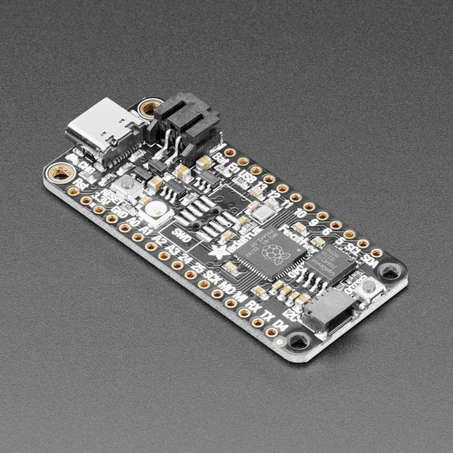
Adafruit Adafruit Feather RP2040
Inside the RP2040 is a 'permanent ROM' USB UF2 bootloader. What that means is when you want to program new firmware, you can hold down the BOOTSEL button while plugging it into USB (or pulling down the RUN/Reset pin to ground) and it will appear as a USB disk drive you can drag the firmware onto. Folks who have been using Adafruit products will find this very familiar – Adafruit uses the technique on all thier native-USB boards. Just note you don't double-click reset, instead hold down BOOTSEL during boot to enter the bootloader!The RP2040 is a powerful chip, which has the clock speed of our M4 (SAMD51), and two cores that are equivalent to our M0 (SAMD21). Since it is an M0 chip, it does not have a floating point unit, or DSP hardware support – so if you're doing something with heavy floating-point math, it will be done in software and thus not as fast as an M4. For many other computational tasks, you'll get close-to-M4 speeds!For peripherals, there are two I²C controllers, two SPI controllers, and two UARTs that are multiplexed across the GPIO – check the pinout for what pins can be set to which. There are 16 PWM channels, each pin has a channel it can be set to (ditto on the pinout).Technical Specifications Measures 2.0 x 0.9 x 0.28' (50.8 x 22.8 x 7 mm) without headers soldered in Light as a (large?) feather – 5 grams RP2040 32-bit Cortex M0+ dual core running at ~125 MHz @ 3.3 V logic and power 264 KB RAM 8 MB SPI FLASH chip for storing files and CircuitPython/MicroPython code storage. No EEPROM Tons of GPIO! 21 x GPIO pins with following capabilities: Four 12 bit ADCs (one more than Pico) Two I²C, Two SPI and two UART peripherals, one is labeled for the 'main' interface in standard Feather locations 16 x PWM outputs - for servos, LEDs, etc The 8 digital 'non-ADC/non-peripheral' GPIO are consecutive for maximum PIO compatibility Built in 200 mA+ lipoly charger with charging status indicator LED Pin #13 red LED for general purpose blinking RGB NeoPixel for full color indication. On-board STEMMA QT connector that lets you quickly connect any Qwiic, STEMMA QT or Grove I²C devices with no soldering! Both Reset button and Bootloader select button for quick restarts (no unplugging-replugging to relaunch code) 3.3 V Power/enable pin Optional SWD debug port can be soldered in for debug access 4 mounting holes 24 MHz crystal for perfect timing. 3.3 V regulator with 500mA peak current output USB Type C connector lets you access built-in ROM USB bootloader and serial port debugging RP2040 Chip Features Dual ARM Cortex-M0+ @ 133 MHz 264 kB on-chip SRAM in six independent banks Support for up to 16 MB of off-chip Flash memory via dedicated QSPI bus DMA controller Fully-connected AHB crossbar Interpolator and integer divider peripherals On-chip programmable LDO to generate core voltage 2 on-chip PLLs to generate USB and core clocks 30 GPIO pins, 4 of which can be used as analog inputs Peripherals 2 UARTs 2 SPI controllers 2 I²C controllers 16 PWM channels USB 1.1 controller and PHY, with host and device support 8 PIO state machines Comes fully assembled and tested, with the UF2 USB bootloader. Adafruit also tosses in some header, so you can solder it in and plug it into a solderless breadboard.
€ 16,95
Leden € 15,26
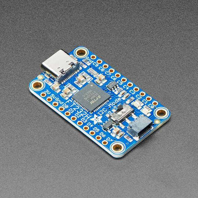
Adafruit Adafruit FT232H Breakout (USB to GPIO, SPI, I²C)
Wouldn't it be cool to drive a tiny OLED display, read a color sensor, or even just flash some LEDs directly from your computer? Sure you can program an Arduino or Trinket to talk to these devices and your computer, but why can't your computer just talk to those devices and sensors itself? Well, now your computer can talk to devices using the Adafruit FT232H breakout board!What can the FT232H chip do? This chip from FTDI is similar to their USB to serial converter chips but adds a 'multi-protocol synchronous serial engine' which allows it to speak many common protocols like SPI, I²C, serial UART, JTAG, and more! There's even a handful of digital GPIO pins that you can read and write to do things like flash LEDs, read switches or buttons, and more. The FT232H breakout is like adding a little swiss army knife for serial protocols to your computer!This chip is powerful and useful to have when you want to use Python (for example) to quickly iterate and test a device that uses I²C, SPI or plain general purpose I/O. There's no firmware to deal with, so you don't have to deal with how to 'send data to and from an Arduino which is then sent to and from' an electronic sensor or display or part.This breakout has an FT232H chip and an EEPROM for onboard configuration.Specifications Dimensions: 23 x 38 x 4 mm (0.9 x 1.5 x 0.2') Weight: 3.4 g DownloadsCAD Files
€ 22,95
Leden € 20,66
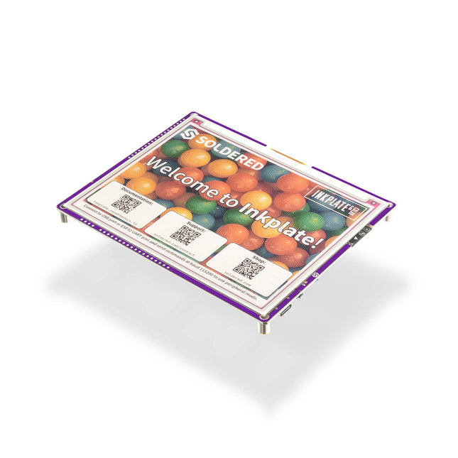
Soldered Soldered Inkplate 6COLOR (with E-paper)
Inkplate 6COLOR continues the tradition of the well-known, user-friendly Inkplate series which is compatible with Arduino and Micropython. Inkplate 6COLOR offers a unique innovation – the ability to display colors on the screen. Inkplate 6COLOR has a 5.85" folded e-paper that displays a total of 7 different colors (Black, White, Red, Yellow, Blue, Green, and Orange). Considering the built-in dithering capability, the results you can get on the screen are really impressive. Powered by ESP32, you will have strong microcontroller with WiFi and Bluetooth on your disposal. It’s super-low-power (18 uA) so you can use it for days, weeks, or months out of a single battery charge. Using our Arduino library (100% compatible with Adafruit GFX), it’s 5 minute work to get the board running for you. The Micropython module is available as well. It’s 100% open-source for both software and hardware. What is especially interesting is that Inkplate uses recycled screens taken from old e-book readers, which is very environmentally friendly, but you have to keep in mind that some screens may have small scratches because of this. All screens with large scratches and damages are not used at all. Features 5.85-inch, 600x448 pixel electronic paper with the ability to display 7 different colors Powered by an ESP32 microcontroller with built-in WiFi and Bluetooth 4.0 (BLE) Consumes extremely small amount of power, whether powered by a lithium battery or USB, in deep sleep mode it consumes only 18 µA, so it will run on one battery for years, and there is also a battery charger located on the board! MicroSD card reader from which Inkplate 6COLOR can extract images to display on its display Additional GPIO lines available, easyC/Qwiic compatibility and I²C and SPI support Arduino library ready (100% compatible with Adafruit GFX) and micropython that enable display of text, images and geometric shapes Dimensions: 131.5 x 105.5 x 10 mm Downloads Arduino library Inkplate documentation Getting started with Inkplate
€ 114,95
Leden € 103,46
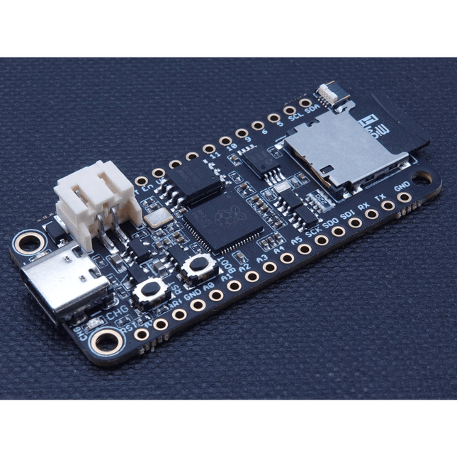
iLabs iLabs Challenger RP2040 SD/RTC
The Challenger RP2040 SD/RTC is an Arduino/CircuitPython compatible Adafruit Feather format microcontroller board based on the Raspberry Pi Pico chip. This board is equipped with an microSD card reader and a Real Time Clock making it super useful for data logging applications. MicroSD Card This board is equipped with a microSD card connector that will house standard microSD cards allowing your application to have many gigabytes of storage room for sensor data or what ever you want to place on it. Together with a fancy display you could also store cool images. Real Time Clock (RTC) MCP79410 is a highly integrated real time clock with nonvolatile memory and many other advanced features. These features include a battery switchover circuit for backup power, a timestamp to log power failures and digital trimming for accuracy. Using a low-cost 32.768 kHz crystal or other clock source, time is tracked in either a 12-hour or 24-hour format with an AM/PM indicator and timing to the second, minute, hour, day of the week, day, month and year. As an interrupt or wakeup signal, a multifunction open drain output can be programmed as an Alarm Out or as a Clock Out that supports 4 selectable frequencies. Specifications Microcontroller RP2040 from Raspberry Pi (133 MHz dual-core Cortex-M0) SPI One SPI channel configured I²C One I²C channel configured UART One UART channel configured Analog inputs 4 analog input channels Flash memory 8 MB, 133 MHz SRAM Memory 264 KB (divided into 6 banks) USB 2.0 controller Up to 12 MBit/s full speed (integrated USB 1.1 PHY) JST Battery connector 2.0 mm pitch On board LiPo charger 500 mA standard charge current RTC MCP79410 (uses I²C0 (Wire) for communication) SD Card One SPI channel used (uses SPI1 to connect to the SD socket) Dimensions 51 x 23 x 3,2 mm Weight 9 g Downloads Datasheet RunCPM image including HW I/O port support CPM File image for RunCPM Getting started with RunCPM for the Challenger RP2040 SD/RTC board CircuitPython download page
€ 17,95
Leden € 16,16


