Tout sur les protocoles et leur mise en œuvre avec Arduino
Initialement destiné aux véhicules routiers, le réseau CAN (« Controller Area Network ») et son successeur le réseau CAN FD (« Flexible Data ») ont vu leurs champs d’application s’élargir à de nouveaux domaines. L’industrie propose de nombreux modules microcontrôleurs dotés d’une interface CAN et/ou CAN FD. L’environnement de développement Arduino a démocratisé la programmation de ces modules et il existe des bibliothèques qui implémentent un pilote CAN et/ou un pilote CAN FD.
La première partie dresse un rapide historique des réseaux CAN et CAN FD et expose la problématique des lignes de transmission en abordant succinctement leur théorie et présentant des résultats de simulation Spice.
La deuxième partie est consacrée au réseau CAN, en détaillant successivement la fonction logique du réseau, les transcepteurs, les contrôleurs, la topologie la plus classique (le bus) et d’autres moins courantes, les répéteurs et les passerelles. Les aspects particuliers du protocole, tels que le bit stuffing, l’arbitrage, les trames d’erreur, la détection des erreurs sont exposés. La discussion de la fiabilité du protocole est illustrée par des exemples mettant en évidence ses faiblesses.
La troisième partie présente le protocole CAN FD, ses deux variantes CAN FD ISO et CAN FD non ISO, leurs fiabilités, leurs faiblesses, mises en évidence par des exemples. Différents transcepteurs et contrôleurs CAN FD sont décrits.
La quatrième partie est dédiée aux applications : comment utiliser les services d’un pilote, concevoir une messagerie, utiliser un analyseur logique. Deux exemples d’application terminent cette partie.
Ce livre s’adresse aux amateurs et aux ingénieurs non spécialistes pour comprendre les possibilités qu’offre un réseau CAN et comment on le met en œuvre. Un enseignant trouvera des informations pour approfondir ses connaissances et pour concevoir des travaux pratiques. Une connaissance des microcontrôleurs, de leur programmation, de l’électronique numérique aidera à la lecture des schémas. La connaissance du langage C++ et du langage de simulation électronique Spice facilitera la compréhension des programmes qui sont décrits dans le livre. Tous les codes source sont disponibles sur le dépôt GitHub de l’auteur.
Téléchargements
GitHub
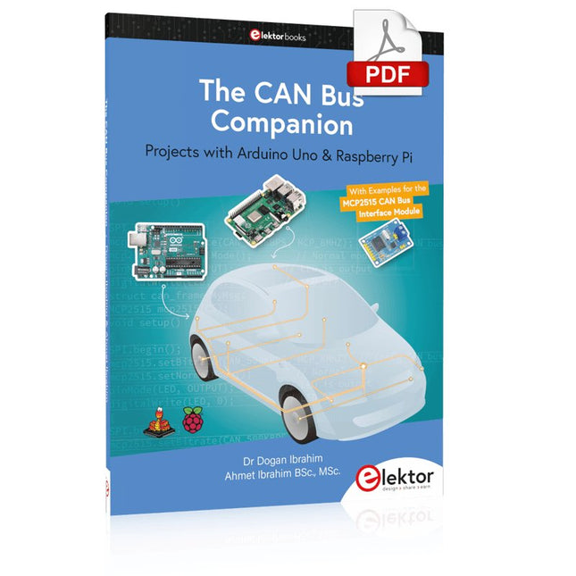
Projects with Arduino Uno & Raspberry Pi with Examples for the MCP2515 CAN Bus Interface Module
This book details the use of the Arduino Uno and the Raspberry Pi 4 in practical CAN bus based projects. Using either the Arduino Uno or the Raspberry Pi with off-the-shelf CAN bus interface modules considerably ease developing, debugging, and testing CAN bus based projects.
This book is written for students, practicing engineers, enthusiasts, and for everyone else wanting to learn more about the CAN bus and its applications. The book assumes that the reader has some knowledge of basic electronics. Knowledge of the C and Python programming languages and programming the Arduino Uno using its IDE and Raspberry Pi will be useful, especially if the reader intends to develop microcontroller-based projects using the CAN bus.
The book should be a useful source of reference material for anyone interested in finding answers to questions such as:
What bus systems are available for the automotive industry?
What are the principles of the CAN bus?
How can I create a physical CAN bus?
What types of frames (or data packets) are available in a CAN bus system?
How can errors be detected in a CAN bus system and how dependable is a CAN bus system?
What types of CAN bus controllers exist?
How do I use the MCP2515 CAN bus controller?
How do I create 2-node Arduino Uno-based CAN bus projects?
How do I create 3-node Arduino Uno-based CAN bus projects?
How do I set the acceptance masks and acceptance filters?
How do I analyze data on the CAN bus?
How do I create 2-node Raspberry Pi-based CAN bus projects?
How do I create 3-node Raspberry Pi-based CAN bus projects?
Functionality, structure and handling of a power module
For readers with first steps in power management the “Abc of Power Modules” contains the basic principles necessary for the selection and use of a power module. The book describes the technical relationships and parameters related to power modules and the basis for calculation and measurement techniques.
Contents
Basics
This chapter describes the need of a DC/DC voltage converter and its basic functionality. Furthermore, various possibilities for realizing a voltage regulator are presented and the essential advantages of a power module are mentioned.
Circuit topologies
Circuit concepts, buck and boost topologies very frequently used with power modules are explained in detail and further circuit topologies are introduced.
Technology, construction and regulation technology
The mechanical construction of a power module is presented, which has a significant influence on EMC and thermal performance. Furthermore, control methods are explained and circuit design tips are provided in this chapter.
Measuring methods
Meaningful measurement results are absolutely necessary to assess a power module. The relevant measurement points and measurement methods are described in this chapter.
Handling
The aspects of storage and handling of power modules are explained, as well as their manufacturing and soldering processes.
Selection of a power modules
Important parameters and criteria for the optimal selection of a power module are presented in this section.
Projects with Arduino Uno & Raspberry Pi with Examples for the MCP2515 CAN Bus Interface Module
This book details the use of the Arduino Uno and the Raspberry Pi 4 in practical CAN bus based projects. Using either the Arduino Uno or the Raspberry Pi with off-the-shelf CAN bus interface modules considerably ease developing, debugging, and testing CAN bus based projects.
This book is written for students, practicing engineers, enthusiasts, and for everyone else wanting to learn more about the CAN bus and its applications. The book assumes that the reader has some knowledge of basic electronics. Knowledge of the C and Python programming languages and programming the Arduino Uno using its IDE and Raspberry Pi will be useful, especially if the reader intends to develop microcontroller-based projects using the CAN bus.
The book should be a useful source of reference material for anyone interested in finding answers to questions such as:
What bus systems are available for the automotive industry?
What are the principles of the CAN bus?
How can I create a physical CAN bus?
What types of frames (or data packets) are available in a CAN bus system?
How can errors be detected in a CAN bus system and how dependable is a CAN bus system?
What types of CAN bus controllers exist?
How do I use the MCP2515 CAN bus controller?
How do I create 2-node Arduino Uno-based CAN bus projects?
How do I create 3-node Arduino Uno-based CAN bus projects?
How do I set the acceptance masks and acceptance filters?
How do I analyze data on the CAN bus?
How do I create 2-node Raspberry Pi-based CAN bus projects?
How do I create 3-node Raspberry Pi-based CAN bus projects?
Elektronische systemen in een voertuig worden steeds belangrijker. Dit wordt mede veroorzaakt door de toenemende milieu- en veiligheidseisen en de wensen ten aanzien van het comfort. Dit leidt niet alleen tot een toename van het aantal regeleenheden (tot 80 stuks in een enkel voertuig) maar deze regeleenheden, die vaak van verschillende leveranciers zijn, moeten ook met elkaar communiceren. Vanaf 2008 is het voor nieuwe voertuigen die voor typegoedkeuring worden aangeboden, verplicht om ten aanzien van emissiegerelateerde storingen via de CAN-bus met een externe diagnosetester te communiceren, volgens een door Europese regelgeving vastgestelde norm. Er wordt uitgebreid aandacht besteed aan de opbouw en werking van het CAN-protocol, gezien vanuit zowel de software als de hardware. Onderwerpen die aan bod komen zijn onder andere de opbouw van een CAN-bericht, de prioriteitsregeling en de fysieke verbinding. Behalve de CAN-bus komt ook EOBD via de CAN-bus uitgebreid aan de orde: hoe werkt EOBD, en welke diagnostische gegevens zijn met behulp van een diagnosetester toegankelijk. De ‘rode draad’ wordt gevormd door de regelgeving van de Europese Unie en de internationale ISO- en SAE-normen. Deze regelgeving en normen moeten er voor zorgen dat de milieubelasting tot een minimum wordt beperkt en een milieugerelateerde storing snel gesignaleerd (en gerepareerd) wordt. Na het doorlezen en bestuderen van de inhoud wordt de CAN-bus en de diagnose via de CAN-bus voor iedereen inzichtelijk; de hobbyist die een CAN-bericht wil begrijpen en eventueel een eigen CAN-bussysteem wil opzetten, de sleutelaar die de storingen van zijn eigen voertuig wil uitlezen en repareren, maar ook de professionele diagnosetechnicus die een lastige fout moet opsporen. Daarnaast kunnen studenten en ontwikkelaars van CAN- en EOBD-applicaties door bestuderen en vooral experimenteren een basis leggen voor eigen toepassingen.
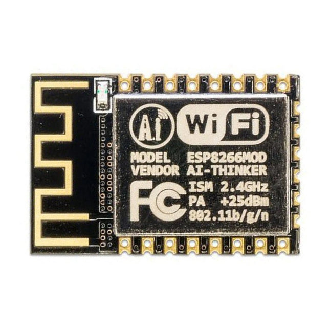
Deze Wi-Fi module is gebaseerd op de populaire ESP8266 chip. De module is FCC en CE gecertificeerd en voldoet aan RoHS. Volledig compatibel met de ESP-12E. 13 GPIO-pinnen, 1 analoge ingang, 4 MB flash-geheugen.
Deze Crowtail serie 4G module is een krachtige LTE Cat1 draadloze module. Hij maakt gebruik van de SIM A7670E communicatiemodule van Simcom, en communiceert via een UART-interface die 4G datatransmissie en spraakcommunicatie mogelijk maakt. De unit ondersteunt meerdere LTE-banden, waaronder B1 / B3 / B5 / B7 / B8 / B20, evenals WCDMA- en GSM-netwerken. Daarnaast ondersteunt hij verschillende protocollen zoals TCP/IP, FTP, HTTP en meerdere satelliet navigatiesystemen zoals GPS, GLONASS en BDS.
De module wordt geleverd met een interface voor het opladen, en kan worden gevoed met een 3,7 V lithium accu of via een 5 V USB-C interface. Hij heeft ook een 3,5 mm koptelefoonaansluiting zodat hij, door een hoofdtelefoon met een microfoon aan te sluiten, kan worden gebruikt voor het maken en ontvangen van telefoongesprekken. Het compacte formaat maakt het eenvoudig om hem te integreren in verschillende IoT-apparaten, en te voldoen aan de eisen van diverse toepassingen. Ook het lage stroomverbruik en de betrouwbare werking behoren tot de redenen waarom hij veel wordt gebruikt bij IoT, smart home, automotive en industriële besturing.
Kenmerken
Bevat de A7670E communicatiemodule, waardoor 4G-gegevensoverdracht en spraakcommunicatie mogelijk zijn met laag stroomverbruik en hoge betrouwbaarheid
Ondersteunt meerdere LTE-banden, waaronder B1 / B3 / B5 / B7 / B8 / B20, evenals WCDMA- en GSM-netwerken
Ondersteunt verschillende protocollen zoals TCP/IP, FTP, HTTP en meerdere satelliet navigatiesystemen zoals GPS, GLONASS en BDS
Wordt geleverd met een interface voor het opladen, en een hoofdtelefoonaansluiting die kan worden gebruikt voor het maken en ontvangen van telefoongesprekken door een hoofdtelefoon met microfoon aan te sluiten
Klein maar krachtig, zíjn compacte formaat maakt het gemakkelijk hem te integreren in verschillende IoT-apparaten.
Specificaties
Hoofd processor: SIM A7670E
LTE-FDD: B1 / B3 / B5 / B7 / B8 / B20
GSM: 900/1800 MHz
GSM/GPRS vermogensklasse
EGSM900: 4 (33 dBm ±2 dB)
DCS1800: 1 (30 dBm ±2 dB)
EDGE vermogensklasse:
EGSM900: E2 (27 dBm ±3 dB)
DCS1800 : E1 (26 dBm +3 dB / -4 dB)
LTE vermogensklasse: 3 (23 dBm ±7 dB)
Voedingsspanning: 4 V ~ 4,2 V
Werkspanning: 3,8 V
LTE (Mbps): 10 (DL) / 5 (UL)
GPRS/EDGE (Kbps): 236.8 (DL) / 236.8 (UL)
Protocol: TCP/IP / IPV4 / IPV6 / Multi-PDP / FTP / FTPS / HTTP / HTTPS / DNS
Communicatie interface: USB / UART
Firmware upgrade: USB / FOTA
Ondersteunde telefoonboek types: SM / FD / ON / AP / SDN
Interfaces: 1x aan/uit-knop, 1x BAT, 1x UART, 1x USB-C, 1x SIM-kaart slot
Afmetingen: 35 x 50 mm
Inbegrepen
1x Crowtail-4G SIM-A7670E
1x 4G GSM NB-IoT antenne
1x GPS keramische antenne
Downloads
Wiki
A7670 AT Command Manual
A7670 Datasheet
Source Code
Using the RFID Starter Kit
An Arduino board has now become ‘the’ basic component in the maker community. No longer is an introduction to the world of microcontrollers the preserve of the expert. When it comes to expanding the capabilities of the basic Arduino board however, the developer is still largely on his own. If you really want to build some innovative projects it’s often necessary to get down to component level. This can present many beginners with major problems. That is exactly where this book begins.
This book explains how a wide variety of practical projects can be built using items supplied in a single kit together with the Arduino board. This kit, called the 'RFID Starter Kit for Arduino' (SKU 17240) is not just limited to RFID applications but contains more than 30 components, devices and modules covering all areas of modern electronics.
In addition to more simple components such as LEDs and resistors there are also complex and sophisticated modules that employ the latest technology such as:
A humidity sensor
A multicolor LED
A large LED matrix with 64 points of light
A 4-character 7-segment LED display
An infra red remote-controller unit
A complete LC-display module
A servo
A stepper motor and controller module
A complete RFID reader module and security tag
On top of that you will get to build precise digital thermometers, hygrometers, exposure meters and various alarm systems. There are also practical devices and applications such as a fully automatic rain sensor, a sound-controlled remote control system, a multifunctional weather station and so much more.
All of the projects described can be built using the components supplied in the Elektor kit.
De MDP-M01 is een display control module uitgerust met een 2,8-inch TFT-scherm. Het scherm kan 90 graden worden gedraaid, wat voor gebruikers handig is om gegevens en golfvormen goed te kunnen bekijken. De MDP-M01 is geschikt voor het online monitoren en beheren van MDP-P906 mini digitale voedingsmodules en andere modules van het MDP-systeem via 2,4 GHz draadloze communicatie, en kan tot 6 submodules tegelijkertijd beheren.
Specificaties
Schermgrootte
2,8' TFT
Schermresolutie
240 x 320 cm
Voeding
Micro USB voedingsingang, of voeding uit een submodule via speciale voedingskabel
Voedingsspanning
DC 5 V / 0,3 A
Andere functies
Kan tot 6 submodules beherenUpgrade firmware via Micro USB
Afmetingen
107 x 66 x 13,6 mm
Gewicht
133 g
Inbegrepen
1x MDP-M01 Smart Digital Monitor
1x kabeltje (2.5 mm jack naar Micro USB)
Downloads
User Manual v3.4
Firmware v1.32
This book is about the Raspberry Pi 3 computer and its use in various control and monitoring applications. The book explains in simple terms and with tested and working example projects, how to configure the Raspberry Pi 3 computer, how to install and use the Linux operating system, and how to write hardware based applications programs using the Python programming language.
The nice feature of this book is that it covers many Raspberry Pi 3 based hardware projects using the latest hardware modules such as the Sense HAT, Swiss Pi, MotoPi, Camera module, and many other state of the art analog and digital sensors. An important feature of the Raspberry Pi 3 is that it contains on-board Bluetooth and Wi-Fi modules. Example projects are given in the book on using the Wi-Fi and the Bluetooth modules to show how real-data can be sent to the Cloud using the Wi-Fi module, and also how to communicate with an Android based mobile phone using the Bluetooth module.
The book is ideal for self-study, and is intended for electronic/electrical engineering students, practising engineers, research students, and for hobbyists. It is recommended that the book should be followed in the given Chapter order.
Over 30 projects are given in the book. All the projects in the book are based on the Python programming language and they have been fully tested. Full program listings of every project are given in the book with comments and full descriptions. Experienced programmers should find it easy to modify and update the programs to suit their needs.
The following sub-headings are given for each project to make it as easy as possible for the readers to follow the projects:
Project title
Description
Aim of the project
Raspberry Pi type
Block diagram
Circuit diagram
Program listing