
Zoekresultaten voor "maitrisez OR les OR microcontroleurs OR a OR l OR aide OR d OR arduino OR b"
-
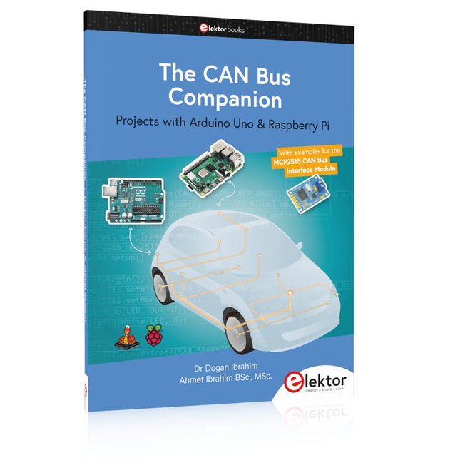
Elektor Publishing The CAN Bus Companion
Projects with Arduino Uno & Raspberry Pi with Examples for the MCP2515 CAN Bus Interface Module This book details the use of the Arduino Uno and the Raspberry Pi 4 in practical CAN bus based projects. Using either the Arduino Uno or the Raspberry Pi with off-the-shelf CAN bus interface modules considerably ease developing, debugging, and testing CAN bus based projects. This book is written for students, practicing engineers, enthusiasts, and for everyone else wanting to learn more about the CAN bus and its applications. The book assumes that the reader has some knowledge of basic electronics. Knowledge of the C and Python programming languages and programming the Arduino Uno using its IDE and Raspberry Pi will be useful, especially if the reader intends to develop microcontroller-based projects using the CAN bus. The book should be a useful source of reference material for anyone interested in finding answers to questions such as: What bus systems are available for the automotive industry? What are the principles of the CAN bus? How can I create a physical CAN bus? What types of frames (or data packets) are available in a CAN bus system? How can errors be detected in a CAN bus system and how dependable is a CAN bus system? What types of CAN bus controllers exist? How do I use the MCP2515 CAN bus controller? How do I create 2-node Arduino Uno-based CAN bus projects? How do I create 3-node Arduino Uno-based CAN bus projects? How do I set the acceptance masks and acceptance filters? How do I analyze data on the CAN bus? How do I create 2-node Raspberry Pi-based CAN bus projects? How do I create 3-node Raspberry Pi-based CAN bus projects?
-

NXP Semiconductors NXP FRDM-MCXN947 Development Board
The FRDM-MCXN947 is a compact and versatile development board designed for rapid prototyping with MCX N94 and N54 microcontrollers. It features industry-standard headers for easy access to the MCU's I/Os, integrated open-standard serial interfaces, external flash memory, and an onboard MCU-Link debugger. Specificaties Microcontroller MCX-N947 Dual Arm Cortex-M33 cores @ 150 MHz each with optimized performance efficiency, up to 2 MB dual-bank flash with optional full ECC RAM, External flash Accelerators: Neural Processing Unit, PowerQuad, Smart DMA, etc. Memory Expansion *DNP Micro SD card socket Connectivity Ethernet Phy and connector HS USB-C connectors SPI/I²C/UART connector (PMOD/mikroBUS, DNP) WiFi connector (PMOD/mikroBUS, DNP) CAN-FD transceiver Debug On-board MCU-Link debugger with CMSIS-DAP JTAG/SWD connector Sensor P3T1755 I³C/I²C Temp Sensor, Touch Pad Expansion Options Arduino Header (with FRDM expansion rows) FRDM Header FlexIO/LCD Header SmartDMA/Camera Header Pmod *DNP mikroBUS User Interface RGB user LED, plus Reset, ISP, Wakeup buttons Inbegrepen 1x FRDM-MCXN947 Development Board 1x USB-C Cable 1x Quick Start Guide Downloads Datasheet Block diagram
-

Elektor Publishing The Book of 555 Timer Projects
Over 45 Builds for the Legendary 555 Chip (and the 556, 558) The 555 timer IC, originally introduced by the Signetics Corporation around 1971, is sure to rank high among the most popular analog integrated circuits ever produced. Originally called the IC Time Machine, this chip has been used in many timer-related projects by countless people over decades. This book is all about designing projects based on the 555 timer IC. Over 45 fully tested and documented projects are presented. All projects have been fully tested by the author by constructing them individually on a breadboard. You are not expected to have any programming experiences for constructing or using the projects given in the book. However, it’s definitely useful to have some knowledge of basic electronics and the use of a breadboard for constructing and testing electronic circuits. Some of the projects in the book are: Alternately Flashing Two LEDs Changing LED Flashing Rate Touch Sensor On/Off Switch Switch On/Off Delay Light-Dependent Sound Dark/Light Switch Tone Burst Generator Long Duration Timer Chasing LEDs LED Roulette Game Traffic Lights Continuity Tester Electronic Lock Switch Contact Debouncing Toy Electronic Organ Multiple Sensor Alarm System Metronome Voltage Multipliers Electronic Dice 7-Segment Display Counter Motor Control 7-Segment Display Dice Electronic Siren Various Other Projects The projects given in the book can be modified or expanded by you for your very own applications. Electronic engineering students, people engaged in designing small electronic circuits, and electronic hobbyists should find the projects in the book instructive, fun, interesting, and useful.
-
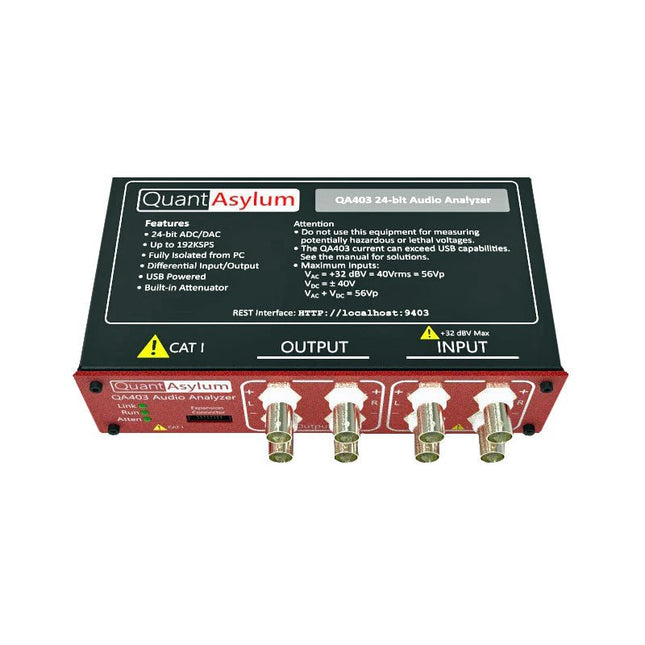
QuantAsylum QuantAsylum QA403 24-bit Audio Analyzer
De QA403 is de vierde generatie audio analyzer van QuantAsylum. Deze QA403 verhoogt de functionaliteit van de QA402 met verbeterde ruis- en vervormingsprestaties, en ook een vlakkere respons aan de randen van de band. Het compacte formaat van de QA403 zorgt ervoor dat u hem vrijwel overal mee naartoe kunt nemen. Kenmerken 24-bits ADC/DAC Tot 192 kS/s Volledig geïsoleerd van de PC Differentiële input/output USB gevoed Ingebouwde demping Snel opstarten en geen stuurprogramma De QA403 is een USB-apparaat zonder stuurprogramma's, wat betekent dat hij meteen operationeel is zodra u hem aansluit. De software is gratis, en u kunt snel en gemakkelijk de hardware van de ene machine naar de andere verplaatsen. Dus als u naar een vestiging moet om een probleem op te lossen, of de QA403 mee naar huis dient te nemen op een thuiswerkdag, dan kunt u dit zonder veel gedoe doen. No-Cal ontwerp De QA403 wordt geleverd met een fabriekskalibratie in het flashgeheugen, waardoor consistente prestaties bij gebruik van meerdere analyzers kan worden gegarandeerd. Op uw productielijn kunt u een andere QA403 installeren en erop vertrouwen dat wat u op de ene analyzer leest overeenkomt met de andere. Er hoeft dus niet geregeld herkalibratie plaats te vinden. Metingen Het uitvoeren van basismetingen kan snel en eenvoudig. In een paar klikken krijgt u inzicht in de frequentierespons, de THD (+ N), de versterking, de SNR, en andere gegevens van uw geteste apparaat. Dynamisch bereik De QA403 biedt 8 gradaties aan versterking op de ingang (0 tot +42 dBV in 6 stappen) en 4 stappen versterking op de uitgang (-12 tot +18 dBV in stappen van 10 dB). Dit zorgt voor consistente prestaties over zeer brede in- en uitgangsniveaus. De maximale AC ingangsspanning op de QA403 is +32 dBV = 40 Vrms. De maximale DC is ±40 V en de maximale ACPEAK + DC = ±56 V. Eenvoudig te programmeren De QA403 ondersteunt een REST-interface, waardoor het eenvoudig is om metingen te automatiseren in vrijwel elke taal. Van Python tot C++ tot Visual Basic: als u weet hoe u een webpagina in uw favoriete taal moet laden dan kunt u al de QA403 op afstand bedienen. Metingen zijn snel en responsief, doorgaans met het verwerken van tientallen opdrachten per seconde. Geïsoleerd, en gevoed via USB De QA403 werkt geïsoleerd van de pc, wat betekent dat u echt uw te testen apparaat meet, en niet met een fantoom aardlus te doen heeft. De QA403 wordt gevoed via USB, zoals bijna alle QuantAsylum instrumenten. Indien u op afstand moet configureren, neem dan een hub met voeding mee in uw tas en uw hele testopstelling kan dan functioneren met een minimum aan kabels. Vaarwel geluidskaart, hallo QA403 Moe van het proberen om een geluidskaart aan de praat te krijgen? Nachtmerries van het kalibreren? Gemis van de juiste versterking? Of te weinig aansturing? Bent u het zat om met vaste ingangsranges om te gaan? Of bang dat u zaken kapot maakt met te veel DC of AC? Moe van de aardlussen? Dáarom heeft QuantAsylum de QA403 ontworpen. Specificaties Afmetingen 177 x 44 x 97 mm (B x H x D) Gewicht 435 g Case Materiaal Aluminium met poedercoating (2 mm dik voorpaneel, 1.6 mm dikke boven/onderkant) Downloads Datasheet Manual GitHub
-
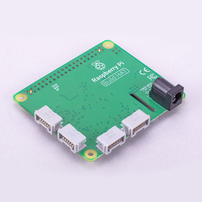
Raspberry Pi Foundation Raspberry Pi Build HAT
Build robust, intelligent machines that combine Raspberry Pi computing power with LEGO components.The Raspberry Pi Build HAT provides four connectors for LEGO Technic motors and sensors from the SPIKE Portfolio. The available sensors include a distance sensor, a colour sensor, and a versatile force sensor. The angular motors come in a range of sizes and include integrated encoders that can be queried to find their position.The Build HAT fits all Raspberry Pi computers with a 40-pin GPIO header, including?–?with the addition of a ribbon cable or other extension device?—?Raspberry Pi 400. Connected LEGO Technic devices can easily be controlled in Python, alongside standard Raspberry Pi accessories such as a camera module.Features Controls up to 4 motors and sensors Powers the Raspberry Pi (when used with a suitable external PSU) Easy to use from Python on the Raspberry Pi
-

Pinecone Pinecone BL602 Evaluation Board
Features Build in USB to Serial interface Build-in PCB antenna Powered by Pineseed BL602 SoC using Pinenut model: 12S stamp 2 MB Flash USB-C connection Suitable to breadboard BIY project On board three color LEDs output Dimensions: 25.4 x 44.0 mm Note: USB cable is not included.
-

Kitronik Kitronik Motor Driver Board voor de Raspberry Pi Pico
Met dit board kan de Raspberry Pi Pico (aangesloten via een pin header) twee motoren tegelijk aandrijven met volledige vooruit, achteruit en stop regeling, waardoor het ideaal is voor Pico gestuurde buggy projecten. Als alternatief kan het board ook gebruikt worden om een stappenmotor aan te drijven. De printplaat is voorzien van het DRV8833 motor driver IC, dat ingebouwde beveiliging tegen kortsluiting, overstroom en oververhitting heeft. De printplaat heeft ook 4 externe aansluitingen op de GPIO pinnen en een 3 V en GND voeding van de Pico. Dit maakt extra IO mogelijkheden mogelijk voor je buggy bouwsels die door de Pico uitgelezen of bestuurd kunnen worden. Bovendien is er een aan/uit schakelaar en een power status LED, zodat je in een oogopslag kunt zien of de printplaat aan staat en je batterijen kunt sparen als je project niet in gebruik is. Om de motor driver kaart te gebruiken moet de Pico een gesoldeerde pin header hebben en stevig in de connector gestoken worden. De kaart heeft een gereguleerde voeding die via de 40-weg connector wordt geleid om de Pico te voeden, zodat je de Pico niet rechtstreeks hoeft te voeden. De motordriver print wordt gevoed via schroefklemmen of via een servo style connector. Kitronik heeft een micro-python module en voorbeeld code ontwikkeld om het gebruik van het Motor Driver board met de Pico te ondersteunen. Deze code is beschikbaar in de GitHub repository. Features Een compact board met veel mogelijkheden, ontworpen als hart van je Raspberry Pi Pico robot buggy projecten. Het board kan 2 motoren tegelijk aansturen met volledige voorwaartse, achterwaartse, en stop regeling. Het bevat de DRV8833 motor driver IC, die ingebouwde beveiliging tegen kortsluiting, overstroom en oververhitting heeft. Bovendien heeft de printplaat een aan/uit schakelaar en een LED voor de voedingsstatus. De voeding van de kaart gaat via een connector in klemmenblokstijl. De 3V en GND pennen zijn ook uitgesplitst, zodat externe apparaten van stroom kunnen worden voorzien. Codeer het met MicroPython via een editor zoals de Thonny editor. Afmetingen: 63 mm (L) x 35 mm (B) x 11,6 mm (H) Download Datasheet
-
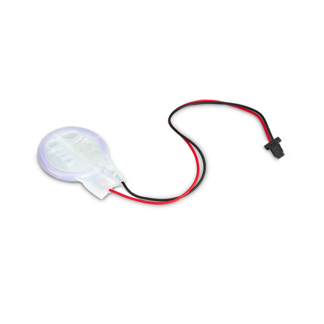
Raspberry Pi Foundation RTC-batterij voor Raspberry Pi 5
The power-management IC used on Raspberry Pi 5 integrates a real-time clock, and charging circuitry for a button cell which can power the clock while main power is disconnected. This Panasonic ML-2020 lithium manganese dioxide battery with a two-pin plug and a double-sided adhesive pad can be connected directly to the battery connector of the Raspberry Pi 5 and attached to the inside of a case or another convenient location.
-
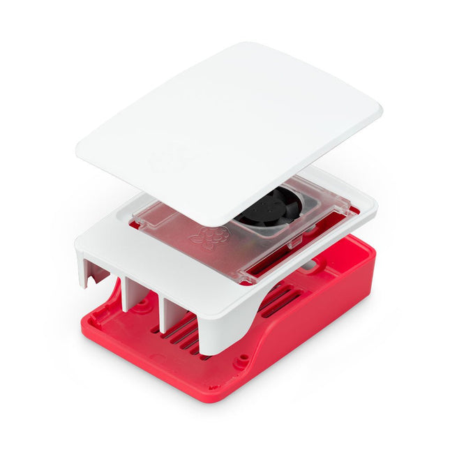
Raspberry Pi Foundation Officiële behuizing voor Raspberry Pi 5 (wit/rood)
De behuizing van de Raspberry Pi 5 is een verfijning van de behuizing van de Raspberry Pi 4, met verbeterde thermische eigenschappen om het hogere piekstroomverbruik van de Raspberry Pi 5 te ondersteunen. Het integreert een ventilator met variabele snelheid die wordt gevoed en bestuurd via een speciale connector op de Raspberry Pi 5.
-
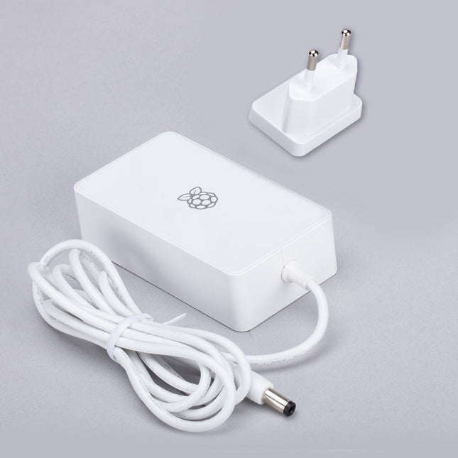
Raspberry Pi Foundation Power Supply for Raspberry Pi Build HAT (48 W)
This 48 W (8 VDC, 6 A) power supply is designed for the use with the Raspberry Pi Build HAT. Input: 110-240 VAC Output: 8 VDC, 6 A Cable: 1.5 m, 16 awg
-

Great Scott Gadgets Great Scott Gadgets HackRF Pro SDR (100 kHz – 6 GHz) + GRATIS e-book
ACTIE: Bestel de HackRF Pro nu en ontvang het nieuwe e-book "SDR with HackRF One & HackRF Pro" ter waarde van € 20 gratis! HackRF Pro is de nieuwste Software Defined Radio (SDR) van Great Scott Gadgets en de krachtige opvolger van de legendarische HackRF One. Met een frequentiebereik van 100 kHz tot 6 GHz bestrijkt het een enorm spectrum voor het verzenden en ontvangen van radiosignalen. Ontworpen als een open-source hardwareplatform, is de HackRF Pro de ideale tool voor het analyseren en ontwikkelen van moderne draadloze technologieën. Het kan flexibel worden gebruikt als USB-randapparaat of worden geprogrammeerd voor zelfstandig (standalone) gebruik. Specificaties Frequentie: 100 kHz tot 6 GHz Instelbaar van 0 Hz tot 7,1 GHz Half-duplex transceiver Tot 20 miljoen samples per seconde 8-bits kwadratuur-samples (8-bits I en 8-bits Q) Compatibel met GNU Radio, SDR# en meer Softwarematig configureerbare RX- en TX-versterking en basisbandfilter Softwarematig geregelde RF-poortvoeding (50 mA bij 3,3 V) SMA RF-connector SMA-klokingang en -uitgang voor synchronisatie en triggering Handige knoppen voor programmering Interne pinheaders voor uitbreiding High-Speed USB 2.0 met USB-C connector Voeding via USB Open source hardware In vergelijking met zijn voorganger, biedt HackRF Pro een aantal nieuwe functies, waaronder: Breder werkfrequentiebereik Verbeterde RF-prestaties met een vlakkere frequentierespons USB-C-connector Ingebouwde TCXO-kristaloscillator voor superieure timingstabiliteit Logica-upgrade van een CPLD naar een energiezuinige FPGA Eliminatie van de DC-piek Uitgebreide precisie-modus met 16-bits samples voor lage samplefrequenties (typische ENOB: 9-11) Halfprecisie-modus met 4-bits samples tot 40 Msps Meer RAM en flashgeheugen voor aangepaste firmware Afscherming rond het radiogedeelte Trigger-ingang en -uitgang toegankelijk via klokconnectoren Uitsparing in de printplaat biedt ruimte voor toekomstige uitbreidingen add-ons Verbeterd energiebeheer Verbeterde bescherming van de RF-poort Mogelijkheid om de zendmodus hardwarematig uit te schakelen Volledige compatibiliteit: Dankzij de beproefde architectuur kan bestaande software voor de HackRF One ook direct worden gebruikt met de HackRF Pro. De HackRF Pro biedt naadloze achterwaartse compatibiliteit en tegelijkertijd aanzienlijk verbeterde prestaties. Let op: Een antenne is niet inbegrepen. Wij raden de ANT500 aan voor een optimale start. Inbegrepen HackRF Pro SDR met kunststofbehuizing Nieuw e-book: SDR with HackRF One & HackRF Pro (normale prijs: € 20) Downloads Documentation GitHub
-
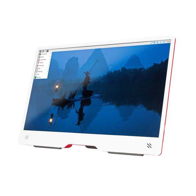
Raspberry Pi Foundation Raspberry Pi Monitor (wit/rood)
De Raspberry Pi Monitor is een 15,6-inch Full HD-computerscherm. Gebruiksvriendelijk, veelzijdig, compact en betaalbaar, het is de perfecte desktop-displaygenoot voor zowel Raspberry Pi-computers als andere apparaten. Met ingebouwde audio via twee naar voren gerichte luidsprekers, VESA- en schroefmontagemogelijkheden en een geïntegreerde in hoek verstelbare standaard is de Raspberry Pi Monitor ideaal voor desktopgebruik of voor integratie in projecten en systemen. Hij kan rechtstreeks van een Raspberry Pi worden voorzien, of via een aparte voeding. Kenmerken 15,6-inch Full HD 1080p IPS-scherm Geïntegreerde in hoek verstelbare standaard Ingebouwde audio via twee naar voren gerichte luidsprekers Audio-uitgang via 3,5 mm-aansluiting HDMI-ingang op volledige grootte VESA- en schroefmontageopties Volume- en helderheidsknoppen USB-C-voedingskabel Specificaties Display Schermgrootte: 15,6 inch, verhouding 16:9 Paneeltype: IPS LCD met antireflectiecoating Weergaveresolutie: 1920 x 1080 Kleurdiepte: 16,2M Helderheid (typisch): 250 nits Kleurgamma: 45% Kijkhoek: 80° Voeding 1,5 A/5 V Kan rechtstreeks worden gevoed via een Raspberry Pi USB poort (max 60% helderheid, 50% volume) of via een aparte voeding (max 100% helderheid, 100% volume) Connectiviteit Standaard HDMI-poort (compatibel met 1.4) 3,5 mm stereohoofdtelefoonaansluiting USB-C (voeding in) Audio 2x 1,2 W geïntegreerde luidsprekers Ondersteuning voor bemonsteringsfrequenties van 44,1 kHz, 48 kHz en 96 kHz Downloads Datasheet


