Zoekresultaten voor "esp OR 32s OR pinboard OR breakout OR modules"
-

Würth Abc of Power Modules (E-book)
Functionality, structure and handling of a power module For readers with first steps in power management the “Abc of Power Modules” contains the basic principles necessary for the selection and use of a power module. The book describes the technical relationships and parameters related to power modules and the basis for calculation and measurement techniques. Contents Basics This chapter describes the need of a DC/DC voltage converter and its basic functionality. Furthermore, various possibilities for realizing a voltage regulator are presented and the essential advantages of a power module are mentioned. Circuit topologies Circuit concepts, buck and boost topologies very frequently used with power modules are explained in detail and further circuit topologies are introduced. Technology, construction and regulation technology The mechanical construction of a power module is presented, which has a significant influence on EMC and thermal performance. Furthermore, control methods are explained and circuit design tips are provided in this chapter. Measuring methods Meaningful measurement results are absolutely necessary to assess a power module. The relevant measurement points and measurement methods are described in this chapter. Handling The aspects of storage and handling of power modules are explained, as well as their manufacturing and soldering processes. Selection of a power modules Important parameters and criteria for the optimal selection of a power module are presented in this section.
€ 8,99
Leden: € 7,19
-

Elektor Digital Elektor Gastredactie door Espressif 2023 (PDF)
Elektor GREEN en GOLD leden kunnen deze uitgave hier downloaden. Nog geen lid? Klik hier om een lidmaatschap af te sluiten. IoT-innovatie in galop Een E-Ink WiFi kleuren-fotolijst ESP-Launchpad tutorialvan nul tot flashen in een paar minuten ESP32 en ChatGPTop weg naar een zelf-programmerend systeem… Walkie-talkie met ESP-NOWniet echt WiFi, niet echt Bluetooth, maar... Van idee tot schakeling met de ESP32-S3zo bouw je een prototype met Espressif-chips AIoT chip-innovatieeen vraaggesprek met Teo Swee-Ann, CEO van Espressif Simuleer ESP32 met Wokwide digitale tweeling van je project Test van de ESP32-S3-BOX-3een uitgebreid AIoT-ontwikkelplatform voor je elektronica-werkplekoverwegingen en tips van Espressif-technici Het ESP RainMaker-verhaalhoe we “jouw” IoT-cloud bouwden Bouw van de Elektor Cloc 2.0een Elektor-product uitgepakt door Espressif De ESP32-P4 ontketendde volgende microcontroller-era Rust + embeddedeen krachtig ontwikkelduo Wie zijn de onvervaarde embedded Rust-ontwikkelaars?zo cultiveert Espressif embedded Rust voor de ESP32 de SoC-serie van Espressif Een PLC met oplossingen van Espressifmet de mogelijkheden en functionaliteit van het ISOBUS-protocol Het ESP32-S3 VGA-boardvolg Bitluni tijdens het ontwerpproces Acoustic fingerprinting met de ESP32songherkenning met het open-source project Olaf Ronde kerstboom 2023een high-tech manier om de feestdagen te vieren Een eenvoudiger en handiger leveneen amateurproject op basis van de ESP8266-module van Espressif IoT-apps bouwen zonder software-expertisemet het Blynk IoT-platform en Espressif-hardware Bouw een slimme gebruikersinterface op ESP32 Snelle en gemakkelijke IoT-ontwikkeling met M5Stack Prototype van een ESP32-gebaseerde energiemeter Een distributeur met meerwaarde voor IoT en meer Achter de schermen: vraaggesprek met Arduino over de Nano ESP32Alessandro Ranellucci en Martino Facchin over de samenwerking met Espressif achter de schermen van Espressif Stroomlijnen van MCU-ontwikkeling met ESP-IDF Privilege Separation Een open-source spraakherkenningsserver......en de ESP BOX Het denkende ooggezichtsherkenning en meer met de ESP32-S3-EYE Knoopcel-schakelaar met ESP32-C2prestatiegericht ontwerpen Matter stuwt het slimme huis voorwaartsontsluit het potentieel van Smart Home IoT Tech the Future: Waarheen met Smarthome IoT?
€ 9,95
-
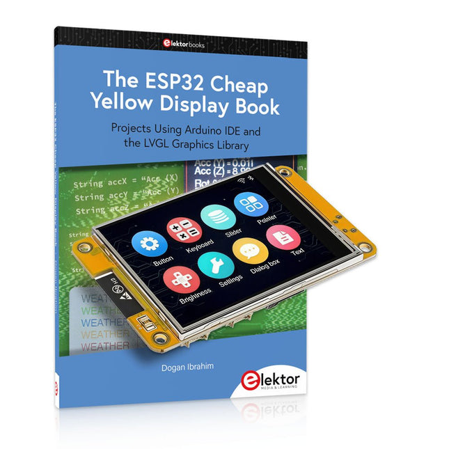
Elektor Bundles The ESP32 Cheap Yellow Display Bundel
Meer dan 40 volledig geteste ESP32-projecten met Arduino IDE en de LVGL grafische bibliotheek Deze bundel bevat de ESP32 Cheap Yellow Display (CYD) – een compact ontwikkelbord dat een standaard ESP32-microcontroller combineert met een TFT-kleurendisplay van 320 x 240 pixels. Het bord beschikt ook over meerdere aansluitingen voor GPIO, seriële communicatie (TX/RX), voeding en aarde. Het ingebouwde display is een groot voordeel, omdat gebruikers hiermee complexe, grafische projecten kunnen maken zonder dat er externe LCD's of displays nodig zijn. Het bijbehorende boek introduceert de hardware en de ingebouwde aansluitingen van het CYD-bord in detail. Het biedt een reeks projecten van beginners- tot gevorderdenniveau, ontwikkeld met de populaire Arduino IDE 2.0. Zowel basis grafische functies als de krachtige LVGL grafische bibliotheek worden behandeld, met praktische projecten die elke aanpak illustreren. Alle meegeleverde projecten zijn volledig getest en klaar voor gebruik. Het boek bevat blokdiagrammen, circuitschema's, complete codelijsten en stapsgewijze uitleg. Met de LVGL-bibliotheek kunnen lezers moderne, kleurrijke grafische interfaces maken met behulp van widgets zoals knoppen, labels, schuifregelaars, kalenders, toetsenborden, grafieken, tabellen, menu's, animaties en meer. ESP32 Cheap Yellow Display Board Dit ontwikkelbord (ook bekend als "Cheap Yellow Display") wordt aangedreven door de ESP-WROOM-32, een dual-core MCU met geïntegreerde Wi-Fi- en Bluetooth-mogelijkheden. Het werkt op een hoofdfrequentie tot 240 MHz, met 520 KB SRAM, 448 KBROM en 4 MB Flash-geheugen. Het bord is voorzien van een 2,8-inch scherm met een resolutie van 240 x 320 en resistieve aanraking. Bovendien bevat het bord een achtergrondverlichtingsbesturingscircuit, aanraakbesturingscircuit, luidsprekeraandrijfcircuit, lichtgevoelig circuit en RGB-LED-besturingscircuit. Het biedt ook een TF-kaartsleuf, seriële interface, DHT11 temperatuur- en vochtigheidssensorinterface en extra IO-poorten. De module ondersteunt ontwikkeling in Arduino IDE, ESP-IDE, MicroPython en Mixly. Toepassingen Beeldoverdracht voor Smart Home-apparaat Draadloze bewaking Slimme landbouw Draadloze QR-herkenning Signaal van draadloos positioneringssysteem En andere IoT-toepassingen Specificaties Microcontroller ESP-WROOM-32 (Dual-core MCU met geïntegreerde Wi-Fi en Bluetooth) Frequentie Tot 240 MHz (rekenkracht is maximaal 600 DMIPS) SRAM 520 KB ROM 448 KB Flash 4 MB Bedrijfsspanning 5 V Stroomverbruik ca. 115 mA Display 2,8" TFT-kleurenscherm (240 x 320) Touch Resistief Touch Driver chip ILI9341 Afmetingen 50 x 86 mm Gewicht 50 g Downloads GitHub Deze bundel bevat: The ESP32 Cheap Yellow Display Book (normale prijs: € 35) ESP32 Cheap Yellow Display Board (normale prijs: € 25) 1x ESP32 Dev Board met 2,8" display en acryl-behuizing 1x Touchpen 1x Aansluitkabel 1x USB-kabel
€ 59,95€ 49,95
Beste prijs
-
Elektor Digital ESP32 & ESP8266 Compilatie (E-book)
De ESP8266 van Espressif is een Wi-Fi microchip met volledige TCP/IP stack en functionaliteit van een microcontroller. Het heeft indruk gemaakt in de maker community met zijn lage prijs. Maar veel ontwikkelaars waren ontevreden over het hoge stroomverbruik van de ESP8266. De ESP32, uitgerust met een ULP (Ultra Low Power) coprocessor, biedt hiervoor een oplossing. Dit e-book bevat een aantal projecten met ESP32 & ESP8266 en een interview met de CEO Teo Swee Ann van Espressif. Artikelen Lichtkrant met ESP-12F, 512 LED’s via WiFi aansturen VFD-klok met ESP32, met nauwkeurige internettijd Zuinige ESP32, de programmering van de ULP-coprocessor DCF77-emulator met ESP8266, internettijd vervangt draadloze tijd WiFi desktop-thermostaat, flexibele en programmeerbare temperatuurregeling Timers voor de WiFi desktop-thermostaat, zeven kanalen met atoomprecisie Zwitsers zakmes voor microcontrollers, PlatformIO als universeel programmeertool ESP8266 USB-programmeer-adapter voor de Espressif-modules ESP-01 en ESP-012 De ESP8266 op het Android I/O-board, zelf nieuwe firmware flashen Weerdisplay, actuele weersinformatie op een kleuren-LCD GoNotify, een flexibele IoT sensor-interface. Join the bubble! CV-monitor met ESP8266, domotica voor de overgang naar duurzame energie MicroPython en het pyboard, van een knipperende LED naar … een knipperende LED aan een webserver De grote broer van de ESP8266, de eerste stappen met de ESP32 en de Arduino-IDE RGBDigit klok, een kleurrijk 7-segment-display voor uw data WLAN voor microcontrollers, besturen met de ESP8266 De terugkeer van de Wi-Fi-besturingskaart, apparatuur bedienen met uw smartphone Compact en autonoom WLAN, handig gebruik van de ESP8266 zonder MCU
€ 9,95
Leden: € 7,96
-
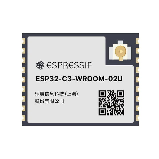
Espressif ESP32-C3-WROOM-02U-N4
De ESP32-C3-WROOM-02U is een Wi-Fi- en Bluetooth LE module voor algemeen gebruik. Het brede scala aan randapparatuur en de hoge prestaties maken deze module tot een ideale keuze voor smart homes, industriële automatisering, zorgtoepassingen, consumentenelektronica, en meer. De ESP32-C3-WROOM-02U is voorzien van een externe SPI flash en wordt geleverd met een aansluiting voor een externe antenne. De ESP32-C3-WROOM-02U werkt in een omgevingstemperatuur van –40 ? 85°C en is ingebouwd in de ESP32-C3 chip. De ESP32-C3 heeft een 32-bits RISC-V single-core processor. Hij bevat een ruime selectie aan randapparatuur, variërend van een UART, I²C, I²S, randapparatuur voor afstandsbediening, een LED PWM controller, een algemene DMA-controller, een TWAI-controller, een USB seriële/JTAG controller, een temperatuursensor, een ADC, enzovoort. Hij bevat ook SPI, Dual SPI en Quad SPI interfaces. Kenmerken Flash: 4 MB (Quad SPI) Afmetingen: 18,0 x 20,0 x 3,2 mm Downloads Datasheet
€ 7,95€ 3,18
Beste prijs
-

Elektor Digital ESP8266 and MicroPython (E-book)
Recently, the development of a tiny chip called the ESP8266 has made it possible to interface any type of microcontroller to a Wi-Fi AP. The ESP8266 is a low-cost tiny Wi-Fi chip having fully built-in TCP/IP stack and a 32-bit microcontroller unit. This chip, produced by Shanghai based Chinese manufacturer Espressif System, is IEEE 802.11 b/g/n Wi-Fi compatible with on-chip program and data memory, and general purpose input-output ports. Several manufacturers have incorporated the ESP8266 chip in their hardware products (e.g. ESP-xx, NodeMCU etc) and offer these products as a means of connecting a microcontroller system such as the Android, PIC microcontroller or others to a Wi-Fi. The ESP8266 is a low-power chip and costs only a few Dollars. ESP8266 and MicroPython – Coding Cool Stuff is an introduction to the ESP8266 chip and describes the features of this chip and shows how various firmware and programming languages such as the MicroPython can be uploaded to the chip. The main aim of the book is to teach the readers how to use the MicroPython programming language on ESP8266 based hardware, especially on the NodeMCU. Several interesting and useful projects are given in the e-book (pdf) to show how to use the MicroPython in NodeMCU type ESP8266 hardware: Project “What shall I wear today?”: You will be developing a weather information system using a NodeMCU development board together with a Text-to-Speech processor module. Project “The Temperature and Humidity on the Cloud”: You will be developing a system that will get the ambient temperature and humidity using a sensor and then store this data on the cloud so that it can be accessed from anywhere. Project “Remote Web Based Control”: You will be developing a system that will remotely control two LEDs connected to a NodeMCU development board using an HTTP Web Server application.
€ 29,95
Leden: € 23,96
-

SunFounder Universal Maker Sensor Kit (voor Raspberry Pi, Pico W, Arduino, ESP32)
Ontdek eindeloze creativiteit met de Universal Maker Sensor Kit, ontworpen voor gebruik met Raspberry Pi, Pico W, Arduino en ESP32. Deze veelzijdige kit biedt compatibiliteit met populaire ontwikkelingsplatforms, waaronder Arduino Uno R4 Minima/WiFi, Uno R3, Mega 2560, Raspberry Pi 5, 4, 3B+, 3B, Zero, Pico W en ESP32. Met meer dan 35 sensoren, actuatoren en displays is het perfect voor projecten variërend van omgevingsmonitoring en slimme huisautomatisering tot robotica en interactief gamen. Stapsgewijze tutorials in C/C++, Python en MicroPython begeleiden zowel beginners als ervaren makers door 169 spannende projecten. Kenmerken Brede compatibiliteit: Ondersteunt volledig Arduino (Uno R3, Uno R4 Minima/WiFi, Mega 2560), Raspberry Pi (5, 4, 3B+, 3B, Zero, Pico W) en ESP32, wat uitgebreide flexibiliteit op verschillende ontwikkelingsplatforms mogelijk maakt. Bevat instructies voor het bouwen van 169 projecten. Uitgebreide componenten: Bevat meer dan 35 sensoren, actuatoren en displaymodules die geschikt zijn voor uiteenlopende projecten zoals omgevingsbewaking, slimme huisautomatisering, robotica en interactieve gamecontrollers. Gedetailleerde tutorials: Biedt duidelijke, stapsgewijze tutorials over Arduino, Raspberry Pi, Pico W, ESP32 en elk inbegrepen component. Tutorials zijn beschikbaar in C/C++, Python en MicroPython, en zijn effectief afgestemd op zowel beginners als ervaren makers. Geschikt voor alle vaardigheidsniveaus: Biedt gestructureerde projecten die zijn ontworpen om gebruikers naadloos te begeleiden van beginners tot gevorderden in elektronica en programmeren, wat de creativiteit en technische expertise vergroot. Inbegrepen Breadboard Knopmodule Capacitieve bodemvochtigheidsmodule Vlamsensormodule Gas-/rooksensormodule (MQ2) Gyroscoop & Accelerometermodule (MPU6050) Hall-sensormodule Infraroodsnelheidssensormodule IR-obstakelvermijdingssensormodule Joystickmodule PCF8591 ADC DAC-convertermodule Fotoweerstandsmodule PIR-bewegingsmodule (HC-SR501) Potentiometermodule Pulsoximeter- en hartslagsensormodule (MAX30102) Regendruppeldetectiemodule Realtimeklokmodule (DS1302) Rotary Encoder-module Temperatuursensormodule (DS18B20) Temperatuur- en vochtigheidssensormodule (DHT11) Temperatuur, vochtigheid en Druksensor (BMP280) Time of Flight Micro-LIDAR afstandssensor (VL53L0X) Touch Sensor Module Ultrasone sensormodule (HC-SR04) Trillingssensormodule (SW-420) Waterniveausensormodule I²C LCD 1602 OLED-displaymodule (SSD1306) RGB LED-module Verkeerslichtmodule 5 V relaismodule Centrifugaalpomp L9110 motordrivermodule Passieve zoemermodule Servomotor (SG90) TT Motor ESP8266-module JDY-31 Bluetooth-module Voedingsmodule Documentatie Online Tutorial
€ 69,95
Leden: € 62,96
-

Elektor Digital Elektor Maart/April 2024 PDF (NL)
Elektor GREEN en GOLD leden kunnen deze uitgave hier downloaden. Nog geen lid? Klik hier om een lidmaatschap af te sluiten. CaptureCountobjectdetector en -teller op de Raspberry Pi 5 Spanningsreferentie met Arduino Pro Minilineariseer en kalibreer analoge ingangen FPGA’s voor beginnersvan MCU naar FPGA-programmering Update: STM32 Wireless Innovation Design Contest 2024 Bluetooth LE met MAUIbesturingsapps voor Android en co. Port Expander breakout-boardmeer I/O’s op je development board AI-specialistmachine learning met de Jetson Nano 2024: een AI-odysseeeen eerste verkenning van TensorFlow 262.144 manieren om Game of Life te spelenlezersproject in het kort Uit het leven gegrepende Chinese draak Draaien met die (DC-borstel)motor!voorbeeldprojecten uit de Elektor Motor Control Development Bundle ESP32/RS-232-adapterdraadloze verbinding voor klassieke meetinstrumenten Alle begin......gaat verder met de opamp Aanbevolen ESP-bibliotheken Piëzo-elektrische componentenvreemde onderdelen Slimme objecttellereenvoudige beeldherkenning met Edge Impulse Oplossingen voor de lastigste uitdagingen bij embedded ontwikkeling ESP32 Terminalhandheld met aanraakscherm Aan de slag met Zephyr RTOSkrachtig – maar lastig... Bekroonde ethiekeen vraaggesprek met Alexander Gerfer, CTO van Würth Elektronik eiSos, over het faciliteren van innovatie en bewust gedrag Project 2.0correcties, updates en brieven van lezers
€ 9,95


Over Elektor
Lees meer
-

, van Johan van den Brande ESP32 Terminal (Review)
De Elecrow ESP32 Terminal is een ESP32-3 aangedreven draagbaar apparaat met een 3,5″ 480 × 320 TFT capacitief touch display en een veelheid aan mogelijkheden. Het apparaat...
-
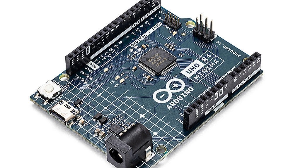
, van Clemens Valens Een review van twee nieuwe Arduino UNO R4-boards: Minima en WiFi
De Arduino UNO R4 Minima en de Arduino UNO R4 WiFi werden een paar maanden geleden aangekondigd, maar zijn nu officieel uitgebracht. Dus nu ze echt...
-

, van Burkhard Kainka Review van de eerste ervaringen met HackRF One
Toen ik de HackRF One voor het eerst in mijn hand hield, wist ik er bijna niets van, behalve dat het een SDR ontvanger en...


