
Zoekresultaten voor "abc OR of OR capacitors"
-

Würth ABC of Capacitors (E-book)
The author Stephan Menzel provides an introduction into capacitor technology and describes the wide range of capacitor types with their properties and parameters. Basic principles This chapter imparts basic knowledge on the relationships between the electric field, permittivity, as well as the structure and operating principles of a capacitor. Capacitor characteristics The electrical parameters and essential characteristics of a capacitor are explained in greater detail for the reader. This extends from the actual capacitance of a capacitor through to the interdependencies. Capacitor types Existing capacitor types and their characteristics are presented. Film, electrolyte and ceramic capacitors are considered in detail.
€ 8,99
Leden: € 8,09
-
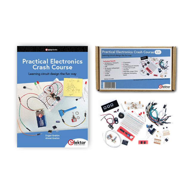
Elektor Bundles Practical Electronics Crash Course (Bundel)
Beginnen met elektronica is niet zo moeilijk als je misschien denkt. Met deze bundel (boek + kit) kun je de belangrijkste concepten van elektrotechniek en elektronica op een leuke manier verkennen en leren door verschillende experimenten uit te voeren. Je leert elektronica op een praktische manier zonder ingewikkeld technisch jargon en lange berekeningen. Het resultaat is dat je snel je eigen projecten zult maken. Deze kit bevat de onderdelen die nodig zijn om de meeste gedetailleerde voorbeelden uit het boek op een breadboard te bouwen en in het echt uit te proberen. De kit kan natuurlijk ook zonder het boek gebruikt worden om andere schakelingen te bouwen en je eigen experimenten te doen. Inhoud van de kit 1x 39 Ω, 1 W weerstand 1x 47 Ω weerstand 1x 180 Ω weerstand 1x 330 Ω weerstand 3x 1 kΩ weerstand 1x 2,2 kΩ weerstand 1x 3,9 kΩ weerstand 1x 6,8 kΩ weerstand 1x 10 kΩ weerstand 1x 15 kΩ weerstand 1x 22 kΩ weerstand 1x 33 kΩ weerstand 1x 47 kΩ weerstand 1x 56 kΩ weerstand 1x 82 kΩ weerstand 1x 120 kΩ weerstand 1x 680 kΩ weerstand 2x 100 kΩ weerstand 1x 10 kΩ-trimmer 1x 10 kΩ lineaire potentiometer 1x 100 kΩ lineaire potentiometer 1x LDR 1x 1 nF keramische condensator 2x 10 nF keramische condensator 1x 100 nF keramische condensator 1x 1 µF, 25 V aluminium elektrolytische condensator 2x 10 µF, 25 V aluminium elektrolytische condensator 1x 100 µF, 25 V aluminium elektrolytische condensator 1x 470 µF, 25 V aluminium elektrolytische condensator 1x 1000 µF, 25 V aluminium elektrolytische condensator 1x RGB-LED, gemeenschappelijke kathode (CC) 1x 1N4148 kleine signaaldiode 1x 1N4733A 5,1 V, 1 W zenerdiode 3x LED, rood 2x BC337 NPN-transistor 1x IRFZ44N N-kanaal MOSFET 2x NE555-timer 1x LM393-vergelijker 1x 74HCT08 quad EN-poort 3x Tactiele schakelaar 2x SPDT-schakelaar 1x relais, SPDT, 9 VDC 1x Actieve zoemer 1x Passieve zoemer 50 cm massieve draad, 16 AWG, zonder mantel 2x PP3 9 V-batterijclip 1x Broodplank 20x verbindingsdraad Deze bundel bevat: Practical Electronics Crash Course Kit (t.w.v. € 45) Boek: Practical Electronics Crash Course (normale prijs: € 45)
€ 89,95€ 69,95Beste prijs
-
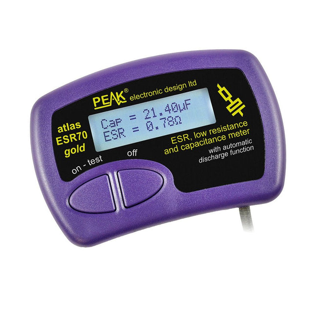
Peak Peak Atlas ESR70 gold (ESR- en capaciteitsmeter)
The Peak Atlas ESR70 gold is an enhanced version of the previous Peak Atlas ESR70 Plus. It does everything that the ESR70 Plus did but better. It now measures capacitance up to 10x faster, and over a wider range, thanks to new test algorithms. The capacitance measurement is also much less influenced by parallel resistances or leakage current thanks to our new Triple-Slope measurement system. Using the supplied gold plated probes (removable), the Atlas ESR70 gold can measure ESR down to a resolution of 0.01 ohms, up to 40 ohms. It can even measure ESR for capacitors that are in-circuit. Probes are removable, allowing 2 mm compatible probes to be fitted. Audible alerts are produced for various ESR levels allowing you to perform many tests in succession without having to look at the display. The ESR70 automatically takes capacitive reactance into account, so even low value capacitors (down to 0.3 uF) can have the ESR measured accurately. Kenmerken Uses a single AAA Alkaline cell (included). Alphanumeric LCD with backlight. Automatic analysis-start when you apply the probes. Automatic capacitor discharge using controlled discharge function. ESR (and low DC resistance) measurement (even in-circuit). Capacitive reactance automatically taken into account to ensure accurate ESR. Capacitance measurement (if testing out-of-circuit). Audible alerts for various ESR levels. Extended ESR measurement range up to 40 Ohms. Optional probe alternatives easily fitted. New gold Features Improved LCD with better backlight. 10x faster capacitance measurement for large capacitors. Enhanced user options system. New triple-slope measurement system to vastly reduce the influence of parallel resistance and/or leakage current on capacitance measurements. Much wider capacitance measurement range now 0.3 uF to 90,000 uF (was 1uF to 22,000uF). Specificaties Analyzer type ESR and Capacitance Component types Capacitors (>0.3 uF) ESR range 0.00 Ohms to 40.0 Ohms ESR resolution From 0.01 Ohms In-circuit use ESR only Capacitance range 0.3 uF to 90000 uF Battery type 1.5 V Alkaline AAA Cell (supplied). Life typically 1500 ops Display type Alphanumeric LCD (with backlight) Inbegrepen Peak Atlas ESR70 gold Extra-long and extra-flexible test cables (450 mm of Silicone covered cable) 2 mm gold plated plugs and sockets with removeable gold plated crocodile clips Comprehensive illustrated user guide AAA Alkaline cell Downloads Datasheet (EN) User Guide (EN)
€ 143,99
-

Würth Abc of Power Modules (E-book)
Functionality, structure and handling of a power module For readers with first steps in power management the “Abc of Power Modules” contains the basic principles necessary for the selection and use of a power module. The book describes the technical relationships and parameters related to power modules and the basis for calculation and measurement techniques. Contents Basics This chapter describes the need of a DC/DC voltage converter and its basic functionality. Furthermore, various possibilities for realizing a voltage regulator are presented and the essential advantages of a power module are mentioned. Circuit topologies Circuit concepts, buck and boost topologies very frequently used with power modules are explained in detail and further circuit topologies are introduced. Technology, construction and regulation technology The mechanical construction of a power module is presented, which has a significant influence on EMC and thermal performance. Furthermore, control methods are explained and circuit design tips are provided in this chapter. Measuring methods Meaningful measurement results are absolutely necessary to assess a power module. The relevant measurement points and measurement methods are described in this chapter. Handling The aspects of storage and handling of power modules are explained, as well as their manufacturing and soldering processes. Selection of a power modules Important parameters and criteria for the optimal selection of a power module are presented in this section.
€ 8,99
Leden: € 8,09
-

Elektor Bundles Learning Digital Electronics (Bundel)
Beheers digitale elektronica – op een praktische manier! Deze bundel bevat het boek Learning Digital Electronics met meer dan 20 praktische projecten in logica- en schakelingontwerp, evenals een 100-delige starterkit – zodat u meteen aan de slag kunt met het bouwen van logische schakelingen, tellers, displays en meer. Learning Digital Electronics (Boek) Dit boek is een praktische gids voor digitale elektronica en behandelt de essentiële componenten van moderne digitale systemen: getallensystemen, logische poorten, Booleaanse algebra, combinatorische en sequentiële logica, en meer. Via meer dan 20 gestructureerde projecten ontwerp en bouw je digitale systemen met behulp van echte componenten zoals logische poorten, multiplexers, decoders, flipflops, tellers en schuifregisters. De projecten variëren van eenvoudige LED-logicacircuits tot digitale sloten, displaysystemen, verkeerslichtcontrollers en timinggebaseerde ontwerpen. Geselecteerde projecten introduceren het gebruik van tools zoals CircuitVerse voor circuitsimulatie, terwijl verschillende ontwerpen gebruikmaken van logische componenten uit de 74HC-serie, die veel worden gebruikt bij het maken van digitale hardwareprototyping. Binnenin vindt u: Duidelijke uitleg over getallensystemen en binaire rekenkunde Fundamentele principes van logische poorten en universele poortimplementaties Stapsgewijze projecten met flipflops, tellers en registers Real-world ontwerp met 74HC-serie logische chips Technieken voor het ontwerpen van combinatorische en sequentiële systemen Dit boek hanteert een ontwerpgerichte, toepassingsgerichte benadering van digitale elektronica – opgebouwd rond werkende circuits, geteste logica en praktische experimenten. Learning Digital Electronics (Kit) Deze kit is speciaal ontwikkeld als aanvulling op het boek "Learning Digital Electronics". Omdat alle benodigde componenten zijn inbegrepen, kunt u elk praktisch project in het boek direct uitvoeren. Inhoud van de kit 2x 74HC08 EN-poortchip 2x 74HC00 NAND-poortchip 1x 74HC86 XOR-poortchip 1x 555 timerchip 1x 74HC161 tellerchip 1x 74HC164 schuifregister 1x CD4511 7-segments decoder 1x CD4027 JK flipflop 1x BC337 NPN-transistor 1x KPS-5161 7-segments gemeenschappelijke-kathodedisplay 1x lichtgevoelige weerstand (LDR) 4x 10 KΩ-weerstanden 8x 1 KΩ weerstand 2x 47 KΩ-weerstanden 1x 100 KΩ weerstand 4x 2,7 KΩ-weerstanden 1x 5,6 KΩ weerstand 1x 150 KΩ weerstand 1x 10 μF condensator 2x 0,01 μF condensator 2x 100 nF condensator 8x Kleine rode LED 1x Kleine groene LED 1x Kleine oranje LED 4x Drukknopschakelaars 1x Actieve zoemer 1x Batterijhouder voor 3x AA-batterijen (batterijen niet inbegrepen) 1x Breadboard 40x Male-to-male jumperdraden (lengte: 200 mm)
€ 69,95€ 59,95Beste prijs
-

FNIRSI FNIRSI LC1020E Hoogprecisie LCR-meter
De FNIRSI LC1020E uiterst nauwkeurige LCR-meter met ESR-tester is een draagbare en intelligente oplossing voor het testen van elektronische componenten, met een basisnauwkeurigheid tot 0,3%. Het apparaat is ideaal voor ingenieurs, technici en makers. Het ondersteunt L/Q-, C/D- en R/D-metingen met behulp van zowel serie- als parallelle equivalente schakelingsmodellen, en is voorzien van een 2,8-inch TFT-kleurenscherm. Met vooraf ingestelde drempelwaarden en audiovisuele waarschuwingen maakt het een snelle goed/fout-evaluatie mogelijk, waardoor het perfect is voor batchtests en kwaliteitscontrole. Het ondersteunt testfrequenties tot 100 kHz en is zeer geschikt voor hoogfrequente analyse van inductoren, condensatoren en weerstanden. Kenmerken Nauwkeurigheid van ±0,05% met een resolutie van 4,5 cijfers Automatische R/L/C-herkenning voor snelle metingen 5 testfrequenties (100 Hz–100 kHz) en 3 spanningsniveaus (0,1–0,6 V) Dubbel display: L/C/R/Z + X/D/Q/θ/ESR Sorteermodus & bias-spanning voor batchtesten Dubbele poorten (3-/5-polig) met ondersteuning voor 4-draads Kelvin Gegevensvasthouden & loggen voor een efficiënte workflow Compact, oplaadbaar (3000 mAh) – ideaal voor gebruik in het lab en in het veld Specificaties Algemeen Testfrequentie 100 Hz, 120 Hz, 1 kHz, 10 kHz, 100 kHz Basisnauwkeurigheid 0,3% Display 2,8-inch TFT LCD-display Weergavecijfers Hoofdparameter: 4,5 cijfers Secundaire parameter: 4,5 cijfers Meetparameters Hoofdparameters: AUTO/R/C/L/Z Secundaire parameters: X/D/Q/θ/ESR Meetbereik L: 0-100H C: 0-100mF R: 0-10M Interne bias 0,0 V, 0,5 V Testniveau 0,1 V, 0,3 V, 0,6 V Kalibratiefuncties Open-circuitkalibratie, kortsluitkalibratie Vergelijkingsfunctie Wordt gebruikt om de relatieve fout tussen de meetwaarde van de component en de nominale waarde te berekenen, weergegeven als een percentage, en biedt filterresultaten. Nominale waarden en tolerantie kunnen worden ingesteld, waarbij het tolerantiebereik instelbaar is van 0,1% tot 99,9% Functieverslag Controleert of de gemeten componentgegevens voldoen aan de ingestelde nominale waarde en tolerantie, waarbij het aantal geslaagde en mislukte metingen wordt geregistreerd Configuratie testklemmen Drie-aansluiting, Vijf-aansluiting Uitgangsimpedantie 100 Ω Interface USB-C (virtuele seriële poort) Overige Taalinstellingen, schermhelderheid, geluidsinstellingen, automatische uitschakeling, kalibratie-instellingen, systeeminformatie Batterij 3000 mAh lithiumbatterij Afmetingen 18,5 x 8,5 x 3,5 cm Gewicht 680 g Capaciteit (C) Bereik: 1mF-100mF 100 Hz: 5% ±5 digits 1 kHz: 3% ±5 digits 10 kHz: / 100 kHz: / Bereik: 1uF-1mF 100 Hz: 1% ±4 digits 1 kHz: 0,5% ±5 digits 10 kHz: 2% ±5 digits 100 kHz: 3% ±4 digits Bereik: 1nF-1uF 100 Hz: / 1 kHz: 0,3% ±2 digits 10 kHz: 0,4% ±2 digits 100 kHz: 1% ±4 digits Bereik: 1pF-1nF 100 Hz: / 1 kHz: 2% ±2 digits 10 kHz: 1,5% ±2 digits 100 kHz: 2% ±4 digits Inductie (L) Bereik: 1H-100H 100 Hz: 2% ±5 digits 1 kHz: 2% ±5 digits 10 kHz: / 100 kHz: / Bereik: 1mH-1H 100 Hz: 0,4% ±5 digits 1 kHz: 0,3% ±2 digits 10 kHz: 0,4% ±3 digits 100 kHz: 2,5% ±5 digits Bereik: 10uH-1mH 100 Hz: 3% ±5 digits 1 kHz: 0,5% ±4 digits 10 kHz: 0,5% ±3 digits 100 kHz: 1,5% ±5 digits Bereik: 1uH-10uH 100 Hz: / 1 kHz: 2% ±5 digits 10 kHz: 2% ±5 digits 100 kHz: 4% ±5 digits Weerstand (R) Bereik: 1MΩ-10MΩ 100 Hz: 5% ±4 digits 1 kHz: 3% ±3 digits 10 kHz: / 100 kHz: / Bereik: 1KΩ-1MΩ 100 Hz: 0,4% ±4 digits 1 kHz: 0,2% ±2 digits 10 kHz: 0,3% ±3 digits 100 kHz: 0,6% ±5 digits Bereik: 1Ω-1KΩ 100 Hz: 1,5% ±4 digits 1 kHz: 0,3% ±2 digits 10 kHz: 0,3% ±3 digits 100 kHz: 0,6% ±5 digits Bereik: 10mΩ-1Ω 100 Hz: 4% ±4 digits 1 kHz: 2% ±5 digits 10 kHz: 2% ±5 digits 100 kHz: 5% ±5 digits Inbegrepen 1x FNIRSI LC1020E LCR-meter 1x Kelvin-meetklem 2x Meetsnoeren (1x zwart, 1x rood) 1x Kortsluitplaat 1x USB-C kabel 1x Manual Downloads Manual Firmware V1.1
€ 84,95€ 69,95Beste prijs
-
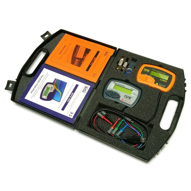
Peak Atlas Pro Pack (LCR45 & DCA75)
This pack contains the LCR45 Passive Component Impedance Meter, great for advanced hobbyists and professionals. It also contains the very popular DCA Pro (model DCA75), fantastic for component identification, pinout identification, detailed characteristic measurement and curve tracing on a PC. Complete with USB cable and software on a USB flash drive. DCA75 Building on the continued success of Peak's existing component identification and analysis instruments, the DCA Pro brings an array of exciting new features for the hobbyist and professional alike. The DCA Pro is an advanced new design that features a graphics display, USB communications, PC Software and an enhanced component identification library. Automatic component type identification Automatic pinout identification (connect any way round) The DCA Pro supports all the components that the popular Peak Atlas DCA55 supports, but adds plenty more. Components supported include: Transistors (including Darlingtons), Silicon and Germanium types. Measures gain, Vbe and leakage MOSFETs, enhancement mode and depletion mode types. Measure on-threshold (at 5 mA) and approx transconductance (for span of 3-5 mA) JFETs, including normally off SiC types. Measures pinch-off voltage (at 1 uA) and approx transconductance (for span of 3-5 mA) IGBTs (insulated gate bipolar transistors). Measures on-threshold (at 5 mA) Diodes and Diode networks LEDs and bicolour LEDs (2 lead and 3 lead types) Zener Diodes with measurement of zener voltage up to 9 V at 5 mA Voltage regulators (measures regulation voltage, drop-out voltage, quiescent current) Triacs and Thyristors that require less than 10 mA of gate current and holding current Stand-alone or with a PC The instrument can be used stand-alone or connected to a PC. Either way, the DCA Pro will automatically identify the component type, identify the pinout and also measure a range of component parameters such as transistor gain, leakage, MOSFET and IGBT threshold voltages, pn characteristics and much more. Curve Tracing When connected to a PC using the supplied USB cable, a range of low current curve-tracing functions can be performed. Various graph types are available, with more to follow: Bipolar transistor output characteristics, IC vs VCE Bipolar transistor gain characteristics, HFE vs VCE Bipolar transistor gain characteristics, HFE vs IC MOSFET and IGBT output function, ID vs VDS MOSFET and IGBT transfer function, ID vs VGS JFET output function, ID vs VDS JFET transfer function, ID vs VGS Voltage regulator, VOUT vs VIN Voltage regulator, IQ vs VIN. PN junction I/V curves, forward and reverse options (for Zener diodes) Curve tracing is performed using test parameters in the range of +/-12 V or +/-12 mA. All curve-tracing data can be instantly pasted into Excel for further graphing and analysis. PC Software is included with the DCA Pro on a Peak USB memory stick. Software designed for Windows 7 and higher (all 32 or 64 bit). LCR45 A great handheld LCR analyser that can measure the value of your passive component (inductor, capacitor or resistor) and also measure the detailed impedance in a number of modes. The LCR45 offers enhanced measurement resolution (better than 0.1 uH!) whilst also giving you continuous fluid measurements. Additionally, the test frequencies of DC, 1 kHz, 15 kHz and 200 kHz can be set to automatic or manual modes. Supplied with removable gold plated hook probes, battery and user guide. Compatible with standard 2 mm test connectors. Not designed for in-circuit use. Automatic or manual component type selection: Inductor, Capacitor or Resistor Automatic or manual test frequency selection: DC, 1 kHz, 15 kHz and 200 kHz Inductance from 0.1 uH to 10 H Capacitance from 0.1 pF to 10,000 uF Resistance from 0.1 Ohm to 2 MOhm Inductance measurement also shows DC winding resistance Display of "Component type and values", "Complex Impedance", "Magnitude/Phase" and "Admittance" Test frequency displayed for all measurements Typical accuracy of 1.5% for inductors and capacitors (see spec table for details) Typical accuracy of 1% for resistors Test lead complete with gold plated 2 mm plugs and sockets Supplied with removable gold plated hook probes Inbegrepen LCR45 DCA75 Extra GP23 Battery Extra AAA cell Dual Carry Case
€ 325,49
-

Elektor Labs Elektor Low-noise Labvoeding
De low-noise labvoeding van Elektor is een volledig analoge, instelbare, symmetrische unit met gemiddeld vermogen, zonder schakelende of digitale componenten. De uitgangsspanning is instelbaar tussen 0 V en ±22 V, en de uitgangsstroom kan worden ingesteld van 0 A tot 1 A. Doordat elke vorm van schakeltechniek wordt vermeden, levert het ontwerp extreem weinig ruis. Voor de weergave van beide uitgangsspanningen en -stromen worden vier kleine analoge paneelmeters met draaispoel gebruikt. De meeste moderne laboratoriumvoedingen en AC-adapters maken gebruik van schakelende technieken. Zelfs de beste uitvoeringen vertonen onvermijdelijk hoogfrequente rimpel en andere schakelartefacten op hun uitgang, die het testen van gevoelige analoge schakelingen kunnen verstoren en metingen van kleine signalen kunnen beïnvloeden. Om dit te voorkomen, is het concept hier een volledig analoge voeding. Hoewel deze minder efficiënt is dan vergelijkbare schakelende voedingen, is de lagere efficiëntie bij gebruik op de testbank nauwelijks van belang en zorgt deze voor schonere en betrouwbaardere meetresultaten. Omdat veel analoge schakelingen een symmetrische voeding vereisen, levert dit ontwerp positieve en negatieve uitgangsspanningen van gelijke grootte. Een kleine hoeveelheid afregeling is beschikbaar om eventuele onbalans te compenseren. Uiteraard is ook een instelbare stroombegrenzing aanwezig. De kit bevat de onderdelen die nodig zijn om de voeding te bouwen, met uitzondering van de transformatoren. Specificaties Uitgangsspanning 0…+22 V, 0, −22 V Uitgangsstroom 0…+1 A, 0…−1 A Ruis −85 dBV (bij 0,95 A/20 V, B = 22 kHz) −84 dBV (bij 0,95 A/20 V, B > 500 kHz) Rimpelspanning 50 µVRMS (bij 950 mA/20 V, B = 22 kHz, voornamelijk 100-Hz-component) Inbegrepen 3x printplaten: regelaar (PCB-1), netfilter (PCB-2) en transformator (PCB-3) Alle componenten, behalve de AC-transformatoren 4x draaispoelmeters Extra onderdelen voor de bedrading (draden, banaanstekkerbussen, IEC-voedingsmodule, enz.) Niet inbegrepen De drie AC-transformatoren Een behuizing Onderdelenlijst Voor de regelaar-printplaat (240386-1) Weerstanden (250 mW, 1%) R1 = 12 Ω R2, R8, R37, R62 = 1 MΩ R3, R7, R10, R13, R17, R20, R22, R30, R35, R42, R45, R47, R55, R60 = 100 Ω, 600 mW R4, R5 = 4.7 kΩ R6 = 100 kΩ R9, R12, R14, R36, R38, R39, R61, R63, R66, R72, R78, R79 = 10.0 kΩ, 600 mW R11 = 9.76 kΩ, 600 mW R15, R40 = 44.2 kΩ, 600 mW R16, R41, R77 = 1 kΩ R18, R43 = 1.5 kΩ, 1 W, 5% R19, R44 = 470 Ω, 1 W, 5% R21, R46 = 330 Ω, 600 mW R23, R24, R48, R49 = 1.0 Ω, 1 W R25, R50 = 1 kΩ, 1 W, 5% R26, R28, R51, R53 = 1.000 kΩ 0.1%, 15 ppm/C R27, R29, R52, R54 = 10.00 kΩ 0.1%, 15 ppm/C R31, R56 = 1.2 kΩ, 1 W, 5% R32, R57 = 47 kΩ R33, R58 = 270 Ω R34, R59 = 27 kΩ R64, R69 = 12.0 kΩ R65 = 3.0 kΩ, 600 mW R67, R80 = 470 Ω, 600 mW R68, R70 = 6.8 kΩ, 600 mW R71 = 30.0 kΩ,, 600 mW R73, R74, R75, R76 = 10 MΩ P1, P2, P3 = 10 kΩ, 200 mW, 20%, potentiometer, 1 turns, single, lin., panel mount P4, P5 = 500 Ω, 500 mW, 10%, trimmer, 25 turns, 3296Y-1-501LF Bourns P6, P7 = 10 kΩ, 500 mW, 10%, trimmer, 25 turns, 3296Y-1-501LF Bourns Condensatoren C1 = 100 nF, 50 V, 10%, ceramic X7R, LS 5 mm C2, C3, C6, C7, C30 = 10 µF, 63V, 20%, LS 2.5 mm, 3000hours@105°C C4, C5, C8, C9, C13, C14, C18, C19, C23, C24, C28, C29, C31, C32, C38, C39 = 100 nF, 250 V, 10%, PET, LS 7.5 mm C10, C20 = 47 nF, 100 V, 5%, PET, LS 5 mm C11, C21 = 10 nF, 100 V, 5%, PET, LS 5 mm C12, C22 = 220 µF, 35 V, 20%, 0.024 Ω, LS2.5/3.5 mm, Ir 3.4 A, 2000hours@125°C, polymer C15, C25 = 120 µF, 50 V, 20%, ESR 0.02 Ω, Diam. 10 mm max., LS 5 mm C16, C26 = 15 nF, 100 V, 5%, PET, LS 5 mm C17, C27 = 47 nF, 100 V, 5%, PET, LS 5 mm C33, C34 = 22 µF, 50 V, 20%, LS 2 mm, 10000 hours @ 105°C C35, C36, C44, C45 = 1 µF, 100 V, 10%, LS 5 mm, ceramic X7R C37 = 100 uF, 50 V, 20%. LS 3.5 mm C40, C41, C42, C43, C46, C47, C48, C49 = 1000 µF, 50 V, 20%, LS 5/7.5 mm, Ir 3.32 A, 10000hours@105°C, D 16 mm C50, C51, C52, C53 = 47 nF, 100 V, 10%, ceramic X7R, LS 5 mm Spoelen L1, L2 = 4.7 µH, 3.2 A, 0.033 Ω, LS 5 mm, RLB0914-4R7ML Bourns L3 = Commom mode choke, 14.5 mH, 3 A, SSRH24NH-30145 Kemet Halfgeleiders D1, D2, D3, D4, D5, D9, D10, D11, D15 = BAT85, DO-34 D6, D7, D12, D13 = SR560, DO-201AD D8, D14, D16 = 1N4148, DO-35 D17 = Zenerdiode, 5.6 V, 0.5 W, DO-41 D18, D19 = 1N4004, DO-41 D20, D21 D22, D23 = V30100CI-M3/P, dual common cathode, TO-220 D24 = Zener diode, 30 V, 1 W, DO-41 LED1, LED2 = LED, red, T-1 (3 mm) LED3, LED4 = LED, green, T-1 (3 mm) TVS1, TVS2 = BZW50-33B, R6 T1, T2, T4 = BC337.25, TO-92 T3 = NJW0302G, TO-3P T5, T6, T8 = BC327.25, TO-92 T7 = NJW0281G, TO-3P T9 = BD139, TO-126 (SOT-32) IC1 = LM334Z, TO-92 IC2 = LM4040AIZ-5.0/NOPB, TO-92 (TO-226AA-3) IC3, IC4 = OPA2992IDR, SOIC-8 IC5, IC6 = OPA4992IDR, SOIC-14 IC7 = OPA992IDBVR, SOT-23-5 IC8 = LM339N, DIP-14 IC9 = LM317, TO-220 IC10 = LM337, TO-220 Overige F1, F2 = 5×20 mm fuse, 1.6 A, fast acting HS1, HS2 = Heatsink MC33271 (for T3/T7), 2.7°C/W, PCB mount, height 63.5 mm K1, K4 = 3-way screw terminal block, LS 3.5 mm, max. 1.5 mm² K2, K3 = 3-way screw terminal block, LS 3.5 mm, max. 1 mm² M1, M3 = Moving coil meter, Range 30 V, type 91C4, 45×45 mm M2, M4 = Moving coil meter, Range 1 A, type 91C4, 45×45 mm² RE1 = Relay DPDT,5V, UA2-5NU Diversen 3× 3-way screw terminal block, LS 3.5 mm, max. 1 mm² (for P1, P2, P3) 4× Pin header, 1×2, vertical, pitch 2.54 mm (for LED1, LED2, LED3, LED4) 4× Pin socket, 1×2, vertical. pitch 2.54 mm (for LED1, LED2, LED3, LED4) 2× Heatsink FK222SA220, 20°C/W, PCB mount (for IC9 & IC10) 2× Mica thermal pad for TO-220, 12×18×0.05 mm (for IC9 & IC10) 2× Insulating bushing IB 6, TO-220 (for IC9 & IC10) 2× Ceramic thermal pad, 23×20×2 mm (for T3 & T7) 2× PCB Fuse Holder, for 5×20 mm fuse, 10 A (for F1, F2) 2× Cover for PCB Fuse Holder, transparent (for F1, F2) 2× 2-way screw terminal block, LS 3.5 mm, max. 1 mm² (for M1 & M3) 2× 2-way screw terminal block, LS 3.5 mm, max. 1.5 mm² (for M2 & M4) 8× M3 solder lug, thickness 0.35 mm (for M1…M4) M4 solder lug, thickness 0.35 mm (to connect 4 mm banana connectors) Screened cable, 1 pair, 2×24 AWG/0.22 mm², 1 m (for P1, P2 & P3) IC socket, DIP, 14 contacts (for IC8) M3 washer, plain, steel M3 screw, 16 mm, steel, pan head M3 nut M3 spring washer 50 mm M3 standoff, steel, male-female 12 mm M3 standoff, steel, male-female 10 mm M3 standoff, steel, male-female M3 screw, 8 mm, steel, pan head Voor de netfilter-printplaat (240386-2) Weerstand R1 = 220 kΩ, 1 W, 500 V, 5% Condensatoren C1, C2 = 470 nF, 305 VAC, Class X2, 11 × 27 mm max., LS 15/22.5 mm C3, C4, C5, C6 = 2.2 nF, 300 VAC, Class Y2, 13 × 4 mm, LS 10 mm, PP Spoelen L1, L2 = Common-mode choke, 6.8 mH, 1.7 A, TDK B82732R2172B030 Halfgeleider MOV1 = TVS varistor, 300 VAC, S14K300 (230 VAC, B72214S0301K101) and SK14K150 (150 VAC, B72214S0151K101) Overige K1, K2 = 3-way screw terminal block, LS 7.62 mm F1 = Time-delay fuse, 0.5 A (230 VAC) or 1 A (115 VAC) Diversen 1× Fuse holder, 5×20 mm, 10 A, 500 VAC 1× Transparent fuse cover 4× 10 mm M3 standoff, steel, male–female 4× M3 screw, 8 mm, steel, pan head 4× M3 nut Voor de transformator-printplaat (240386-3) Weerstanden R1, R2 = 2.7 kΩ, 600 mW, 1% R3 = 10.0 kΩ, 600 mW, 1% Condensator C1 = 220 µF, 50 V, 20%, Ø10 mm, LS 5 mm, 4000 h @ 105°C Transformatoren (niet inbegrepen in deze kit!) TR1, TR2, TR3 = 2×7 V, 25 VA, PCB-mounted toroid, 70060K Talema Halfgeleiders D1–D4 = 1N4148, DO-35 D5, D6 = 1N4004, DO-41 D7 = Zener 5.6 V, 1.3 W, DO-41 LED1 = LED, red, T-1 (3 mm) IC1, IC2 = MOC8021M, CTR ≥ 1000%, DIP-6 Overige F1, F2, F3 = 160 mA time-delay fuse (230 VAC) or 315 mA time-delay fuse (115 VAC) K1 = 2-way screw terminal block, LS 7.62 mm K2 = 3-way screw terminal block, LS 3.5 mm, max 1.5 mm² K3, K4 = 3-way screw terminal block, LS 3.5 mm, max 1 mm² RE1, RE2 = Relay DPDT, 5 A/250 VAC / 24 VDC Diversen 1× Pin header 1×2, pitch 2.54 mm + matching socket for LED1 3× Fuse holder 5 × 20 mm, 10 A, 500 VAC + transparent cover 3× M4 screw, 8 mm, pan head + washer for TR1-TR3 8× M3 screw, 8 mm, pan head + nut + washer 8× 10 mm M3 standoff, steel, male–female 2× IC socket, DIP-6 for IC1 & IC2 Extra onderdelen 1 m red insulated wire, stranded, 1.5 mm² 0.5 m blue insulated wire, stranded, 1.5 mm² 0.5 m black insulated wire, stranded, 1.5 mm², 0.5 m 2 m red insulated wire, stranded, D 0.56 mm (0.25 mm²) 2 m black insulated wire, stranded, D 0.56 mm (0.25 mm²) 0.5 m Multicore Cable, Flexible, 3 Core, 0.75 mm² (24 x 0.2 mm) Red banana socket Black banana socket Blue banana socket Green banana socket IEC Power Entry Module with switch, IEC C14 3 crimp terminals, FASTON, 4.75 x 0.81 mm 3 knobs Links Elektor Labs JumpStarter Page Artikel (deel 1) Artikel (deel 2)
€ 299,00€ 249,00Beste prijs
-

Elektor Zenerdiode-tester
De Elektor Zenerdiode-tester is in wezen een constante-stroombron die in stappen van 1 tot 50 mA kan worden geschakeld. Hij kan worden gebruikt om zenerdiodes tot een maximum van 54 V te testen. Dankzij een 60-V step-upconverter kan het apparaat worden gevoed met de gebruikelijke 5 tot 12 V. Het principe van deze tester is eenvoudig. Een zenerdiode of een ander DUT (device under test, zoals een LED) wordt gevoed door een instelbare stroombron. De spanning over het DUT kan met een multimeter worden gemeten. De spanning van de meeste (kleine) zenerdiodes wordt gespecificeerd bij een stroom van 5 mA. Afhankelijk van de toepassing kan ook de spanning bij andere stromen interessant zijn. Daarom zijn er zes stroominstellingen beschikbaar: 1, 2, 5, 10, 20 en 50 mA. LED’s worden vaak gespecificeerd bij een stroom van 20 mA. Wat kan worden getest: Of een zenerdiode defect is (kortsluiting of hoogohmig). Of een zenerdiode de juiste zenerspanning heeft. Hoe een zenerspanning verandert bij verschillende stromen. Welke exacte spanning aanwezig is bij een geïntegreerde spanningsreferentie. Of LED’s in een serieschakeling verschillen in helderheid (vandaar de stroom van 20 mA). Wat de stroomversterking is bij verschillende basisstromen in (vermogens)transistoren. De kit bevat alle onderdelen die in de stuklijst staan vermeld, inclusief printplaat en behuizing. Specificaties Voedingsspanning 5…12 V/2 A (USB-C) Voedingsstroom (Itest = 50 mA) 1,1 A bij 5 V / 412 mA bij 12 V Selecteerbare stromen 1, 2, 5, 10, 20 en 50 mA Max. testspanning >54 V bij Itest ≥1 mA Max. uitgangsspanning 60 V bij Itest = 0 mA Spanningslimiet bij 5 V 4,5 V bij Itest = 1 mA / 5,18 V bij Itest = 50 mA Afmetingen (behuizing) 110 x 82 x 44 mm Afmetingen (PCB) 105,4 x 67,3 mm Aansluitingen 4 mm banaanstekkerbussen voor multimeter 2 mm banaanstekkerbussen voor testklemmen USB-C-aansluiting voor voeding Inbegrepen Weerstanden R1 = 3.3 kΩ, 600 mW, 1% R2 = 0.15 Ω, 1 W, 5%, LS 12.7 mm, ø 3.5 mm R3, R8 = 180 Ω, 600 mW, 1% R4, R6, R16 = 1 kΩ, 600 mW, 1% R5, R19 = 47 kΩ, 600 mW, 1% R7 = 3.9 kΩ, 1 W, 5%, LS 12.7 mm, ø 3.5 mm R9, R10, R12 = 10 kΩ, 600 mW, 1% R11, R13 = 100 Ω, 600 mW 1% R14 = 249 Ω, 600 mW, 1% R15 = 499 Ω, 600 mW, 1% R17 = 2.49 kΩ, 250 mW, 1% R18 = 4.99 kΩ, 250 mW, 1% Condensatoren C1 = 470 uF / 35 V, 20%, Ir = 1.86 A, ø 12.5 mm, LS 5 mm, ESR = 0.038 Ω (Panasonic EEUTP1V471) C2 = 1 uF / 100 V, 10%, X7R, LS 5 mm C3 = 2.2 nF / 50 V, 10%, X7R, LS 5 mm C4, C7 = 100 nF / 100 V, 10%, X7R, LS 5 mm C5 = 100 uF / 100 V, 20%, ø 14 mm max., LS 5 mm C6 = 1 nF / 100 V, 10%, X7R, LS 5 mm Inductor L1 = 100 uH, Irms = 2.4 A, Isat = 3.5 A, 0.09 Ω, radial, pitch 2.5/5/10 mm, ø 14 mm max. (Kemet SBC8-101-242) Halfgeleiders D1 = MUR120G, DO-41 D2, D4 = STPS3150RL, DO-201AD D3 = Z-diode, 18 V, 1.3 W (BZX85C18) D5 = Z-diode, 5.1 V, 0.5 W (1N5231B) LED1 = LED in pushbutton S1 LED2 = LED, green, 3 mm IC1 = MC34063, DIP-8 IC2 = LM4040BIZ-5.0/NOPB, TO-92 (TO-226AA-3) IC3 = TL051CP, DIP-8 T1 = BC327.25, TO-92 T2 = STP40NF10L, TO-220 T3 = IRF9510PBF, TO-220 T4 = 2N7000, TO-92 Overige K1, K2, S1, S3 = 2-way screw terminal block, LS 3.5 mm, max. 1.5 mm² connected to K1 = USB-C socket, 30 V/3 A, chassis mounted, wired, 9 x 16 mm connected to K2 = Banana Connector, 2 mm, Socket, 60 VDC, Panel Mount, red (Multicomp 24.102.1) connected to K2 = Banana Connector, 2 mm, Socket, 60 VDC, Panel Mount, black (Multicomp 24.102.2) Test clip, red, 30 VAC/60 VDC (Hirschmann 931467101) Test clip, black, 30 VAC/60 VDC (Hirschmann 931467100) S1 = Pushbutton, panel mount, SPST-NO, 30 DC/100 mA, with red LED S2 = Rotary Switch, 6 position, 2 pole, 30°, 250 V/150 mA S3 = Toggle switch, panel mount, SPDT, solder lugs, 28 VDC T2, T3 = Heat sink, 15°C/W, FK 214 SA-CB Enclosure Hammond 1591XXSSBK, ABS, 110 x 82 x 44 mm Knob for S2, round shaft 6 mm, ø 21 mm, with indicator line (Multicomp CP-LB21-6-6D) 4 x Self-tapping screw #4-1/4", carbon steel, pan head Banana plug, red, 2 mm, 60 VDC (Multicomp 25.205.1) Banana plug, black, 2 mm, 60 VDC (Multicomp 25.205.2) Banana socket, black 4 mm, panel mount Banana socket, red 4 mm, panel mount for LED1, LED2 = Pin header, 1 x 2, vertical, pitch 2.54 mm for LED1, LED2 = Pin socket, 1 x 2, vertical, pitch 2.54 mm for T2, T3 = M3 screw, 10 mm, steel, pan head 2 x M3 washer, plain, steel 4 x M3 nut for IC1, IC3 = DIP-8 socket Wire, black, 0.25 mm² (24 AWG), stranded 14 x 0.15 mm, 1 m Wire, red, 0.25 mm² (24 AWG), stranded 14 x 0.15 mm, 1 m PCB 250772-1 v1.1 Links Artikel Elektor Labs
€ 99,95€ 84,95Beste prijs
-
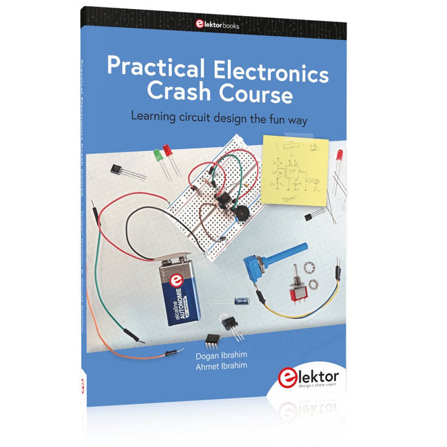
Elektor Publishing Practical Electronics Crash Course
Learning circuit design the fun way Welcome to the world of electronics! Getting started in electronics is not as difficult as you may think. Using this book, you will explore and learn the most important electrical and electronics engineering concepts in a fun way by doing various experiments and by simulating circuits. It will teach you electronics practically without getting into complex technical jargon and long calculations. As a result, you will be creating your own projects soon. No prior knowledge of electronics is required, only some basic algebra is used in a few simple calculations. Many tested and working projects and simulations are presented to familiarise yourself with the construction of electronic circuits. Circuit simulation is introduced at an early stage to enable you to experiment with circuits easily without breaking anything. You will learn: The concepts of voltage, current, and power AC and DC Basic lamp circuits with switches Passive components: resistors, capacitors & inductors RC & RCL circuits Electromagnetism Loudspeakers, relays, buzzers, and transformers Active components: diodes & LEDs, bipolar transistors & MOSFETs Transistor-based switching circuits Optocoupler circuits Astable & monostable multivibrators Using the 555 timer IC The operational amplifier Digital logic Advanced examples: amplifiers, oscillators, filters, and sensors Test and measurement tools Microcontrollers: Arduino UNO, ESP32, Raspberry Pi Pico, and Raspberry Pi Reading datasheets and best practices for selecting components EMC & EMI and norms & regulations
€ 39,95
Leden: € 35,96


-

, van Clemens Valens Unleashing the Power of the Miniware MHP50: A Compact Hot Plate for Preheating and Reflow Soldering
The Miniware MHP50 isn't just another hot plate for preheating circuit boards—it's a versatile tool that's perfect for reflow soldering on smaller boards. Let’s dive into...
-

, van Clemens Valens Fnirsi HRM-10 Interne Weerstandstester voor batterijen, een review
Nu in toenemende mate alles op batterijen werkt, neemt de behoefte aan een tool om batterijen te testen en te repareren toe. Ik besprak al...

