
Zoekresultaten voor "joy OR it OR um25c OR usb OR measuring OR device"
-

Elektor Digital Elektor Circuit Special 2025 (PDF) NL
Elektor GREEN en GOLD leden kunnen deze uitgave hier downloaden. Nog geen lid? Klik hier om een lidmaatschap af te sluiten. USB-meetadaptertest stroom en signaalkwaliteit van USB-poorten 4...20 mA stroom-uitgang voor Arduino Unobetrouwbare, EMI-ongevoelige current loop-interface Automatische stofzuigerschakelaarhoud uw werkplek schoon DDS-generator met ATtiny Opamp-tester v2nieuwe print – nu ook voor SMD’s 550-mW audio ‘Lamp-Amp’voor die warme buizenklank Zekeringbewakerhoud zekeringen in de gaten met een knipper-LED Hoogwaardige RIAA-voorversterkerhaal het beste uit uw vinylplaten! Kalibratie voor draaitafelsArduino-gebaseerde 100/120Hz-stroboscoop Elektor Classics: Video-versterker Dimmer met IR-afstandsbedieningcomfortabel en elegant staande halogeen- of LED-lampen regelen Het gebruik van switch…case bij strings in C++/Arduino IDE Magneetzoekermet een eenvoudige Hall-effect-sensor Raspberry Pi: slimme aan/uit-knopeen oplossing voor de Raspberry Pi tot aan model 4 Professionele tipsvan makers voor makers Praktische projecten met de 555-timerDC-motorbesturing en snelle reactie-uitdaging Eenvoudige ‘aan-verklikker’spaar energie met een simpele schakeling Powerpacks parallelschakelendrie dagen ononderbroken stroom VFO tot 15 MHzimplementatie met Raspberry Pi Pico Vioolstemmer met ATtiny202 Elektor Classics: Video-ingangsversterker voor zwart/wit-TV Capaciteitsmeter20 pF tot 600 nF Quasi-analoog uurwerk Mk IItwee LED-ringen – voor uren en minuten Niets is onmogelijk(met hulp van het Arduino-ecosysteem) Neon dobbelsteen Elektor Classics: RTTY-afstemhulp Inspirerende hardware-ontwerpen voor uw ESP’s Elektor Classics: 3 A voeding RGB-LED’s met geïntegreerde stuurkringlicht met precisie: ICLED’s zetten de standaard Experiment: een mixed-signal Theremin?moderne time-of-flight sensoren plus de tijdloze analoge XR2206 ESP32 audio-transceiver (deel 1)SD-kaart WAV-speler demo Elektor infographicschakelingen en schakelingontwerp 2025 Kleine audiomixereenvoudig, veelzijdig en schaalbaar Slimme timer voor trapverlichtingbespaar op uw energierekening! Maak uw rolluiken slimmerVelux-hardware besturen met een ESP32 en MQTT Solid-state voetenwarmercomfortabel en energiezuinig Is de M5Stamp Fly-quadcopter de nieuwe Tello? Vergroot het WiFi-bereik van de ESP32-C3 SuperMinieenvoudige en effectieve antennemodificatie ZD-8968 hetelucht-soldeerstationbudgetvriendelijk werkpaard of gebakken lucht? Parkeersensor-testervind defecten in het PDC-systeem van een auto
€ 9,95
-

OWON OWON SDS1104 4-kanaals Oscilloscoop (100 MHz)
De OWON SDS1104 oscilloscoop is een praktische keuze voor engineers, technici, studenten en hobbyisten die nauwkeurige signaalanalyse nodig hebben zonder de kosten van hoogwaardige meetinstrumenten. Met een bandbreedte van 100 MHz en een samplingrate van 1 GSa/s legt hij laag- tot middenfrequente signalen betrouwbaar vast, waardoor hij zeer geschikt is voor elektronicaontwikkeling, foutopsporing en educatief gebruik. Uitgerust met een 7-inch kleuren-TFT-display biedt de SDS1104 een duidelijke weergave van golfvormen, terwijl automatische meetfuncties en FFT-analyse gebruikers helpen om frequentie-, spannings- en timingparameters snel te beoordelen. Geavanceerde wiskundige bewerkingen, cursormetingen en meerdere triggermodi zorgen voor extra flexibiliteit, waardoor de oscilloscoop een veelzijdig hulpmiddel is voor uiteenlopende testsituaties. Specificaties Bandwidth 100 MHz Sample Rate 1 GS/s Horizontal Scale (s/div) 5ns/div - 1000s/div, step by 1 - 2 - 5 Channel 4 Display 7" color LCD, 800 x 480 pixels Input Coupling DC, AC and GND Vertical Resolution (A/D) Vertical Resolution (A/D) Vertical Sensitivity 5mV/div - 5V/div (at input) Trigger Type Edge, Video Trigger Mode Auto, Normal and Single Waveform Math +, -, x, ÷, invert, FFT Fuse 2A, T class, 250 V Dimension (W x H x D) 301 x 152 x 70 mm Weight 1.1 kg Inbegrepen 1x OWON SDS1104 Oscilloscope 1x Mains power cord 1x CD Rom 1x Quickstart Guide 1x USB Cable 4x Oscilloscope probe 1x Probe Adjust Downloads Datasheet Manual
€ 249,00
-
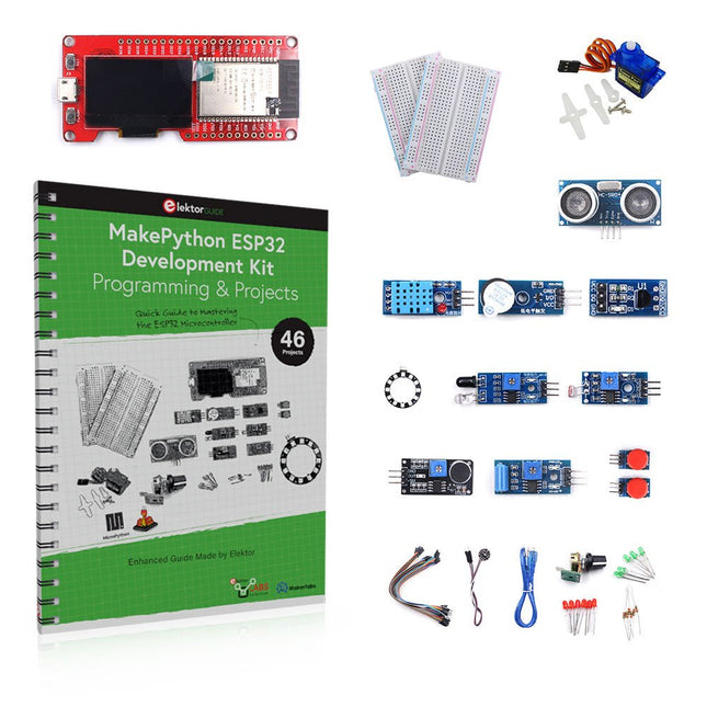
Elektor Bundles MakePython ESP32 Development Kit (EN)
Leer hoe je de ESP32 Microcontroller en het programmeren met MicroPython in je toekomstige projecten kunt gebruiken! Het (Engelstalige) projectboek, geschreven door de bekende Elektor auteur Dogan Ibrahim, bevat vele software- en hardware-gebaseerde projecten die speciaal voor de MakePython ESP32 ontwikkelkit ontwikkeld zijn. De kit wordt geleverd met verschillende LED's, sensoren, en actuatoren. De kit helpt je de basiskennis op te doen om eigen IoT projecten te maken. Alle volledig geëvalueerde projecten in het boek zijn voorzien van de bijgeleverde componenten. Elk project bevat een blokschema, een schakelschema, een volledige programmalijst, en een volledige programma beschrijving. Inbegrepen in de kit 1x MakePython ESP32 ontwikkelingsboard met LCD 1x Ultrasone afstandsmeter 1x Temperatuur- en luchtvochtigheidssensor 1x Zoemer module 1x DS18B20 module 1x Infrarood module 1x Potentiometer 1x WS2812 module 1x Geluidssensor 1x Trilsensor 1x Module met lichtgevoelige weerstand 1x Puls sensor 1x Servo motor 1x USB kabel 2x Knop 2x Breadboard 45x Schakeldraad 10x Weerstand 330R 10x LED (Rood) 10x LED (Groen) 1x Projectboek (Engelstalig, 206 pagina's) Boek met 46 projecten LED Projecten Knipperende LED SOS knipperende LED Knipperende LED – met behulp van een timer Afwisselend knipperende LEDs Knopbediening De knippersnelheid van de LED's veranderen met drukknop onderbrekingen Chasing-LEDs Binaire teller met LEDs Kerstverlichting (willekeurig-knipperende 8 LEDs) Elektronische dobbelsteen Geluksdag van het week Projecten voor Pulsewidth Modulation (PWM) Genereer een PWM golfvorm van 1000 Hz met 50% duty cycle LED helderheid regelen Meten van de frequentie en duty cycle van een PWM golfvorm Melodieën maker Eenvoudig elektronisch orgel Servo motor besturing Servo motor DS18B20 thermometer Projecten voor analoog naar digitaal converteren (ADC) Voltmeter Plotten van de analoge ingangsspanning Interne temperatuursensor van de ESP32 Ohmmeter Lichtgevoelige weerstandsmodule Projecten voor digitaal naar analoog converteren (DAC) Opwekken van vaste spanningen Opwekken van een zaagtand-golf signaal Opwekken van een driehoek-golf signaal Golfvorm met willekeurige periode Genereren van een sinus-golf signaal Genereren van een nauwkeurig sinus-golf signaal met behulp van een timer interrupts Gebruik van het OLED Display Seconden teller Gebeurtenisteller DS18B20 digitale thermometer met OLED ON-OFF temperatuur regelaar Meten van temperatuur en luchtvochtigheid Ultrasone afstandsmeting Hoogte van een persoon (stadiometer) Hartslag (polsslag) meten Andere bij de set geleverde sensoren Diefstal alarm Met geluid geactiveerd licht Infrarood obstakel-vermijding met zoemer WS2812 RGB LED ring Tijdregistratie van temperatuur en luchtvochtigheid Netwerkprogrammering Wi-Fi scanner Bediening op afstand vanuit de Internet browser (met een smartphone of PC) – Webserver Temperatuur- en luchtvochtigheidsgegevens opslaan in de Cloud Werking met Low-Power Gebruik een timer om de processor te laten ontwaken
€ 89,95€ 69,95Beste prijs
-
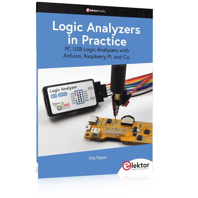
Elektor Publishing Logic Analyzers in Practice
PC USB Logic Analyzers with Arduino, Raspberry Pi, and Co. Step-by-step instructions guide you through the analysis of modern protocols such as I²C, SPI, UART, RS-232, NeoPixel, WS28xx, HD44780 and 1-Wire. With the help of numerous experimental circuits based on the Raspberry Pi Pico, Arduino Uno and the Bus Pirate, you will learn the practical application of popular USB logic analyzers. All the experimental circuits presented in this book have been fully tested and are fully functional. The necessary program listings are included – no special programming or electronics knowledge is required for these circuits. The programming languages used are MicroPython and C along with the development environments Thonny and Arduino IDE. This book uses several models of flexible and widely available USB logic analyzers and shows the strengths and weaknesses of each price range. You will learn about the criteria that matter for your work and be able to find the right device for you. Whether Arduino, Raspberry Pi or Raspberry Pi Pico, the example circuits shown allow you to get started quickly with protocol analysis and can also serve as a basis for your own experiments. After reading this book, you will be familiar with all the important terms and contexts, conduct your own experiments, analyze protocols independently, culminating in a comprehensive knowledge set of digital signals and protocols.
€ 34,95
Leden: € 31,46
-

tinySA tinySA Ultra+ ZS407 Spectrumanalyzer
The tinySA Ultra+ ZS-407 is a compact, handheld spectrum analyzer and signal generator. Covering 100 kHz to 7.3 GHz in Ultra mode, it lets you visualize and analyze RF signals from HF right through many modern wireless bands – and can even spot signals up to ~12 GHz thanks to harmonic tracking. The intuitive 4-inch resistive touchscreen and rechargeable battery make it great for fieldwork, while features like a built-in signal generator, switchable bandpass filters, step attenuator, USB-PC control and auto-calibration add serious versatility. Kenmerken Screen size: 4 inch (480 x 320) Spectrum Analyzer for 0.1-900 MHz or, with Ultra mode enabled up to 7.3 GHz, level calibrated up to 7.3 GHz. Can observe signals up to 12 GHz Signal Generator with sine wave output between 0.1-900 MHz or square wave up to 6.3 GHz or RF test signal output up to 7.3 GHz when not used as Spectrum Analyzer. Switchable resolution bandpass filters from 200 Hz to 850 kHz Built-in 20 dB optional LNA Color display showing max 450 points providing gapless covering up to the full frequency range. MicroSD card slot for storing measurements, settings and screen captures. Specificaties (Spectrumanalyzer) Input frequency range from 100 kHz to 900 MHz in normal mode and up to 7.3 GHz with ULTRA mode enabled Input impedance 50 ohm when input attenuation set to 10 dB or more. Selectable manual and automatic input attenuation between 0 dB and 31 dB in 1 dB steps when LNA not active Maximum +/-5V DC input Absolute maximum input level of +6 dBm with 0 dB internal attenuation Absolute maximum short term peak input power of +20 dBm with 30 dB internal attenuation Suggested maximum input power of +0 dBm with internal attenuation in automatic mode For best measurements keep input power below -25 dBm Input Intercept Point of third order modulation products (IIP3) of +15 dBm with 0 dB internal attenuation 1 dB compression point at -1 dBm with 0 dB internal attenuation Power detector resolution of 0.5 dB and linearity versus frequency of ±2 dB below 5.3 GHz, ±5dB between 5.3 GHz and 6 GHz Minimum burst length for correct level measurement at 850 kHz RBW in zero span mode of 50 microseconds Absolute power level accuracy after power level calibration of ±2 dB Built-in optional 20 dB LNA with Noise Figure of 5 dB up to 6 GHz Lowest discernible signal without LNA at 30 MHz using a resolution bandwidth of 30 kHz of -102 dBm Lowest discernible signal with LNA at 30 MHz using a resolution bandwidth of 200 Hz of -145 dBm Frequency accuracy equal to the selected resolution bandwidth Phase noise at 30 MHz of -108 dB/Hz at 100 kHz offset and -115 dB/Hz at 1MHz offset Spur free dynamic range when using a 30 kHz resolution bandwidth of 70 dB Resolution filters with a width of 0.2, 1, 3, 10, 30, 100, 300, 600 and 850 kHz On screen resolution of 51, 101, 145, 290 or 450 measurement points. Scanning speed of over 1000 points/second using largest resolution filters. Automatic optimization of actual scanning points to ensure coverage of the whole scan range regardless of the chosen resolution bandwidth Spur suppression option for assessing if certain signals are internally generated or actually present in the input signal Headphone output for listening to the demodulated audio (AM only). Stereo connector with or without microphone, high impedance is louder, short protected Specificaties (Signaalgenerator) Sine wave output with harmonics below -40 dB of fundamental from 100 kHz to 900 MHz Output level selectable in 1 dB steps between -115 dBm and -19 dBm Above 800 MHz choice of two output modes: Cleanest signal mode: square wave, up to 6 GHz with coarse frequency steps and less accurate output level Highest accuracy mode: reduced harmonics with possibly strong spurs up to 7.3 GHz with frequency resolution equal to below 800 MHz and fine output level steps Level accuracy ±2 dB up to 800 MHz between -72 dBm and -19 dBm, less accuracy below -72 dBm, even less accuracy below -110 dBm Output frequency resolution 57.2 Hz Optional AM or FM modulation frequencies between 50 Hz and 5 kHz (AM) or 1 kHz (FM) or sweep over selectable frequency span AM modulation depth between 10% and 100% FM deviation between 1 kHz and 300 kHz Optional output level sweep over maximum the entire output level range Inbegrepen 1x tinySA Ultra+ ZS407 Spectrum Analyzer 2x SMA connection cables 1x Barrel connector 1x Antenna with SMA connector 1x USB-C cable 1x microSD card (32 GB) Downloads Wiki
€ 196,02
-

Rigol Rigol DSA815-TG Spectrumanalyzer (9 kHz – 1.5 GHz)
Highlights Frequency: 1.5 GHz DANL: -155 dBm Phase Noise: -80 dBc/Hz RBW: 10 Hz Tracking Generator Specificaties All-Digital IF Technology Frequency Range from 9 kHz up to 1.5 GHz Min. -161 dBm Displayed Average Noise Level (Typ.) Min. < -98 dBc/Hz @ 10 kHz Offset Phase Noise Level Measurement Uncertainty < 0.8 dB 10 Hz Minimum Resolution Bandwidth Up to 1.5 GHz Tracking Generator Advanced Measurement Functions (Opt.) EMI Filter & Quasi-Peak Detector Kit (Opt.) VSWR Measurement Kit (Opt.) PC Software (Opt.) Optional RF TX/RX Training Kit Optional RF Accessories (Cable, Adaptor, Attenuator, Bridge ...) Complete Connectivity: LAN (LXI), USB Host & Device, GPIB (Opt.) 8 Inch WVGA (800x480) Display Compact Size, Light Weight Design Inbegrepen 1x Rigol DSA815-TG Spectrumanalyzer 1x Power cord 1x USB cable
€ 974,66
-

Siglent Siglent SDS1204X-E 4-kanaals Oscilloscoop (200 MHz)
The Siglent SDS1204X-E is a powerful 200 MHz four-channel oscilloscope that is built on the same platform as the very popular SDS1202X-E but with several significant improvements, including two 1 GSa/s ADCs and two 14 Mpt memory modules. Waveform capture rates are up to 100,000 wfms/s in normal mode and 400,000 wfms/s in sequence mode. The SDS1000X-E scopes feature a large 7” 256-level color display with intensity grading and color temperature features. Specificaties Bandwidth 200 MHz Sampling Rate (Max.) 1 GSa/s Channels 2CH+EXT4CH Memory Depth (Max.) 7 Mpts/CH (not interleave mode); 14 Mpts/CH (interleave mode) Waveform Capture Rate (Max.) 100,000 wfms/s (normal mode), 400,000 wfms/s (sequence mode) Trigger Types Edge, Slope, Pulse width, Window, Runt, Interval, Dropout, Pattern, Video Serial Trigger (Standard) I2C, SPI, UART/RS232, CAN, LIN Decode Type (Standard) I2C, SPI, UART/RS232, CAN, LIN 16 Digital Channels (four channel series only, option) Maximum waveform capture rate up to 1 GSa/s, Record length up to 14 Mpts/CH USB AWG module (four channel series only, option) One channel, 25 MHz, sample rate of 125 MHz, wave length of 16 kpts Bode plot ( four channel series only) Minimum start frequency of 10 Hz, minimum scan bandwith of 500 Hz, maximum scan bandwidth of 120 MHz (dependent on Oscilloscope and AWG bandwidth), 500 maximum scan frequency points USB WIFI adapter (four channel series only, option) 802.11b/g/b, WPA-PSK, the adapter must be supplied by Siglent to ensure proper functioning Downloads Datasheet Manual Programming Guide
€ 781,44
-
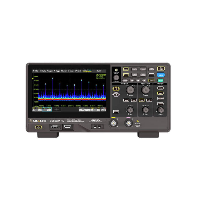
Siglent Siglent SDS822X HD 2-kanaals Oscilloscoop (200 MHz)
The Siglent SDS822X HD digital storage oscilloscope is based on 2 GSa/s, 12-bit Analog-Digital Converters and front ends with excellent noise floor performance. With a 200 MHz bandwidth, and a maximum record length of 100 Mpts, and the capability to analyze 2 analog channels alongside 16 digital channels, the SDS822X HD is perfectly suited for mixed signal analysis. Kenmerken 12-bit High Resolution 12-bit Analog-Digital Convertors with sample rate up to 2 GSa/s Front ends with 70 μVrms noise floor @ 200 MHz bandwidth 2/4 analog channels, up to 700 MHz bandwidth SPO technology Waveform capture rate up to 120,000 wfm/s (normal mode), and 500,000 wfm/s (sequence mode) Supports 256-level intensity grading and color temperature display modes. Up to 50 Mpts record length Digital trigger system Intelligent trigger: Edge, Slope, Pulse width, Window, Runt, Interval, Dropout, Pattern, Video (HDTV supported), Qualified, Nth edge, Delay, Setup/Hold time. Serial bus triggering and decoder, supports protocols I²C, SPI, UART, CAN, LIN. Segmented acquisition (Sequence) mode, dividing the maximum record length into multiple segments (up to 80,000), according to trigger conditions set by the user, with a very small dead time between segments to capture the qualifying event. History waveform record (History) function, the maximum recorded waveform length is 80,000 frames. Automatic measurements on 50+ parameters, supports statistics with histogram, track, trend, Gating measurement, and measurements on Math, History and Ref. 4 Math traces (2 Mpts FFT, addition, subtraction, multiplication, division, integration, differential, square root, etc.), supports formula editor. Abundant data analysis functions such as Search, Navigate, Counter, Bode plot and Power Analysis High Speed hardware-based Mask Test function, with Mask Editor tool for creating user-defined masks 16 digital channels (optional) 25 MHz waveform generator (optional) 7" TFT-LCD display with 1024 x 600 resolution; Capacitive touch screen supports multi-touch gestures. Interfaces include: USB Hosts, USB Device (USBTMC), LAN (VXI-11/Telnet/Socket), Pass/Fail, Trigger Out Built-in web server supports remote control over the LAN port using a web browser. Supports SCPI remote control commands. Supports external mouse and keyboard. Supports NTP. Specificaties Analog Channels 2 Bandwidth 200 MHz Vertical resolution 12-bit Sample rate (Max.) One channel mode: 100 Mpts/chTwo channel mode: Mpts/chFour channel mode: 25 Mpts/ch Memory depth (Max.) One channel mode: 50 Mpts/chTwo channel mode: 25 Mpts/ch Waveform capture rate (Max.) Normal mode: 120,000 wfm/sSequence mode: 500,000 wfm/s Trigger type Edge, Slope, Pulse width, Window, Runt, Interval, Dropout, Pattern, Video, Qualified, Nth edge, Delay, Setup/Hold time, Serial Serial trigger and decode (Standard) I²C, SPI, UART, CAN, LIN Measurement 50+ parameters, statistics, histogram, trend, and track supported Math 4 traces 2 Mpts FFT, Filter, +, -, x, ÷, ∫dt, d/dt, √, Identity, Negation, Absolute, Sign, ex, 10x, ln, lg, Interpolation, MaxHold, MinHold, ERES, Average. Supports formula editor Data analysis Search, Navigate, History, Mask Test, Counter, Bode plot, and Power Analysis Digital channel (optional) 16-channel; maximum sample rate up to 1 GSa/s; record length up to 10 Mpts USB AWG module (option) One channel, 25 MHz, sample rate of 125 MHz, wave length of 16 kpts, isolated output I/O 2x USB 2.0 Host, USB 2.0 Device, 10/100 M LAN, Auxiliary output (TRIG OUT, PASS/FAIL), SBUS (Siglent MSO) Probe (Standard) Passive probe PB470 for each channel Display 7 TFT-LCD with capacitive touch screen (1024x600) Inbegrepen 1x Siglent SDS822X Oscilloscope 2x Passive probe (200 MHz) PP520 1x Power cord (EU) 1x USB cable 1x Certificate of calibration 1x Quick start Downloads Datasheet Manual Programming guide
€ 635,25
-
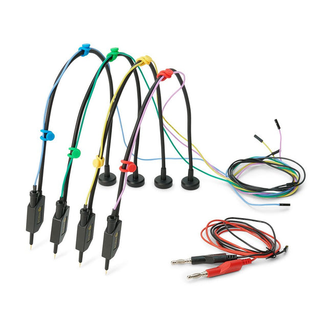
Sensepeek Sensepeek 6005 4x SQ10 Probe incl. Test Wires
The SQ series of handsfree PCBite probes from Sensepeek are insulated, come with included color-coded cable holders and have a lower point of gravity making them even more stable compared with the original SP series of probes. All the loved features of handsfree measurement, exchangeable fine pitch spring tipped test needle and the minimalistic design is maintained to make traditional sized and handheld probes obsolete. Features All handsfree probes from Sensepeek makes instant measurements or long triggering sessions a breeze. No more soldering wires to connect your probe or complicated tools to setup, just positioning the probe needle on any test point or component in the signal path and release. Saves time and frustration during development, verification and repairs. The minimalist design and the spring-loaded test needle makes it possible to simultaneously measure on fine pitch components and nearby signals. Both length and weight of the SQ probes are perfectly balanced to be used with PCBite PCB holders and base plate which is a must for handsfree function. The probe holder comes with a powerful magnet in the base, as for all PCBite probes and holders which makes the probe easy to place and reposition. The SQ series of probes can be used handheld without the probe holder as they have an insulated grip but their full potential is used when measuring handsfree. Included 4x SQ10 probes and pin tipped test needles (black) 2x Banana to dupont test wires (red/black) 5x Dupont to dupont test wires 1x Set of cable holders (4 colors) 4x Extra test needles Downloads User guide
€ 107,69
-

Elektor Labs Elektor Low-noise Labvoeding
De low-noise labvoeding van Elektor is een volledig analoge, instelbare, symmetrische unit met gemiddeld vermogen, zonder schakelende of digitale componenten. De uitgangsspanning is instelbaar tussen 0 V en ±22 V, en de uitgangsstroom kan worden ingesteld van 0 A tot 1 A. Doordat elke vorm van schakeltechniek wordt vermeden, levert het ontwerp extreem weinig ruis. Voor de weergave van beide uitgangsspanningen en -stromen worden vier kleine analoge paneelmeters met draaispoel gebruikt. De meeste moderne laboratoriumvoedingen en AC-adapters maken gebruik van schakelende technieken. Zelfs de beste uitvoeringen vertonen onvermijdelijk hoogfrequente rimpel en andere schakelartefacten op hun uitgang, die het testen van gevoelige analoge schakelingen kunnen verstoren en metingen van kleine signalen kunnen beïnvloeden. Om dit te voorkomen, is het concept hier een volledig analoge voeding. Hoewel deze minder efficiënt is dan vergelijkbare schakelende voedingen, is de lagere efficiëntie bij gebruik op de testbank nauwelijks van belang en zorgt deze voor schonere en betrouwbaardere meetresultaten. Omdat veel analoge schakelingen een symmetrische voeding vereisen, levert dit ontwerp positieve en negatieve uitgangsspanningen van gelijke grootte. Een kleine hoeveelheid afregeling is beschikbaar om eventuele onbalans te compenseren. Uiteraard is ook een instelbare stroombegrenzing aanwezig. De kit bevat de onderdelen die nodig zijn om de voeding te bouwen, met uitzondering van de transformatoren. Specificaties Uitgangsspanning 0…+22 V, 0, −22 V Uitgangsstroom 0…+1 A, 0…−1 A Ruis −85 dBV (bij 0,95 A/20 V, B = 22 kHz) −84 dBV (bij 0,95 A/20 V, B > 500 kHz) Rimpelspanning 50 µVRMS (bij 950 mA/20 V, B = 22 kHz, voornamelijk 100-Hz-component) Inbegrepen 3x printplaten: regelaar (PCB-1), netfilter (PCB-2) en transformator (PCB-3) Alle componenten, behalve de AC-transformatoren 4x draaispoelmeters Extra onderdelen voor de bedrading (draden, banaanstekkerbussen, IEC-voedingsmodule, enz.) Niet inbegrepen De drie AC-transformatoren Een behuizing Onderdelenlijst Voor de regelaar-printplaat (240386-1) Weerstanden (250 mW, 1%) R1 = 12 Ω R2, R8, R37, R62 = 1 MΩ R3, R7, R10, R13, R17, R20, R22, R30, R35, R42, R45, R47, R55, R60 = 100 Ω, 600 mW R4, R5 = 4.7 kΩ R6 = 100 kΩ R9, R12, R14, R36, R38, R39, R61, R63, R66, R72, R78, R79 = 10.0 kΩ, 600 mW R11 = 9.76 kΩ, 600 mW R15, R40 = 44.2 kΩ, 600 mW R16, R41, R77 = 1 kΩ R18, R43 = 1.5 kΩ, 1 W, 5% R19, R44 = 470 Ω, 1 W, 5% R21, R46 = 330 Ω, 600 mW R23, R24, R48, R49 = 1.0 Ω, 1 W R25, R50 = 1 kΩ, 1 W, 5% R26, R28, R51, R53 = 1.000 kΩ 0.1%, 15 ppm/C R27, R29, R52, R54 = 10.00 kΩ 0.1%, 15 ppm/C R31, R56 = 1.2 kΩ, 1 W, 5% R32, R57 = 47 kΩ R33, R58 = 270 Ω R34, R59 = 27 kΩ R64, R69 = 12.0 kΩ R65 = 3.0 kΩ, 600 mW R67, R80 = 470 Ω, 600 mW R68, R70 = 6.8 kΩ, 600 mW R71 = 30.0 kΩ,, 600 mW R73, R74, R75, R76 = 10 MΩ P1, P2, P3 = 10 kΩ, 200 mW, 20%, potentiometer, 1 turns, single, lin., panel mount P4, P5 = 500 Ω, 500 mW, 10%, trimmer, 25 turns, 3296Y-1-501LF Bourns P6, P7 = 10 kΩ, 500 mW, 10%, trimmer, 25 turns, 3296Y-1-501LF Bourns Condensatoren C1 = 100 nF, 50 V, 10%, ceramic X7R, LS 5 mm C2, C3, C6, C7, C30 = 10 µF, 63V, 20%, LS 2.5 mm, 3000hours@105°C C4, C5, C8, C9, C13, C14, C18, C19, C23, C24, C28, C29, C31, C32, C38, C39 = 100 nF, 250 V, 10%, PET, LS 7.5 mm C10, C20 = 47 nF, 100 V, 5%, PET, LS 5 mm C11, C21 = 10 nF, 100 V, 5%, PET, LS 5 mm C12, C22 = 220 µF, 35 V, 20%, 0.024 Ω, LS2.5/3.5 mm, Ir 3.4 A, 2000hours@125°C, polymer C15, C25 = 120 µF, 50 V, 20%, ESR 0.02 Ω, Diam. 10 mm max., LS 5 mm C16, C26 = 15 nF, 100 V, 5%, PET, LS 5 mm C17, C27 = 47 nF, 100 V, 5%, PET, LS 5 mm C33, C34 = 22 µF, 50 V, 20%, LS 2 mm, 10000 hours @ 105°C C35, C36, C44, C45 = 1 µF, 100 V, 10%, LS 5 mm, ceramic X7R C37 = 100 uF, 50 V, 20%. LS 3.5 mm C40, C41, C42, C43, C46, C47, C48, C49 = 1000 µF, 50 V, 20%, LS 5/7.5 mm, Ir 3.32 A, 10000hours@105°C, D 16 mm C50, C51, C52, C53 = 47 nF, 100 V, 10%, ceramic X7R, LS 5 mm Spoelen L1, L2 = 4.7 µH, 3.2 A, 0.033 Ω, LS 5 mm, RLB0914-4R7ML Bourns L3 = Commom mode choke, 14.5 mH, 3 A, SSRH24NH-30145 Kemet Halfgeleiders D1, D2, D3, D4, D5, D9, D10, D11, D15 = BAT85, DO-34 D6, D7, D12, D13 = SR560, DO-201AD D8, D14, D16 = 1N4148, DO-35 D17 = Zenerdiode, 5.6 V, 0.5 W, DO-41 D18, D19 = 1N4004, DO-41 D20, D21 D22, D23 = V30100CI-M3/P, dual common cathode, TO-220 D24 = Zener diode, 30 V, 1 W, DO-41 LED1, LED2 = LED, red, T-1 (3 mm) LED3, LED4 = LED, green, T-1 (3 mm) TVS1, TVS2 = BZW50-33B, R6 T1, T2, T4 = BC337.25, TO-92 T3 = NJW0302G, TO-3P T5, T6, T8 = BC327.25, TO-92 T7 = NJW0281G, TO-3P T9 = BD139, TO-126 (SOT-32) IC1 = LM334Z, TO-92 IC2 = LM4040AIZ-5.0/NOPB, TO-92 (TO-226AA-3) IC3, IC4 = OPA2992IDR, SOIC-8 IC5, IC6 = OPA4992IDR, SOIC-14 IC7 = OPA992IDBVR, SOT-23-5 IC8 = LM339N, DIP-14 IC9 = LM317, TO-220 IC10 = LM337, TO-220 Overige F1, F2 = 5×20 mm fuse, 1.6 A, fast acting HS1, HS2 = Heatsink MC33271 (for T3/T7), 2.7°C/W, PCB mount, height 63.5 mm K1, K4 = 3-way screw terminal block, LS 3.5 mm, max. 1.5 mm² K2, K3 = 3-way screw terminal block, LS 3.5 mm, max. 1 mm² M1, M3 = Moving coil meter, Range 30 V, type 91C4, 45×45 mm M2, M4 = Moving coil meter, Range 1 A, type 91C4, 45×45 mm² RE1 = Relay DPDT,5V, UA2-5NU Diversen 3× 3-way screw terminal block, LS 3.5 mm, max. 1 mm² (for P1, P2, P3) 4× Pin header, 1×2, vertical, pitch 2.54 mm (for LED1, LED2, LED3, LED4) 4× Pin socket, 1×2, vertical. pitch 2.54 mm (for LED1, LED2, LED3, LED4) 2× Heatsink FK222SA220, 20°C/W, PCB mount (for IC9 & IC10) 2× Mica thermal pad for TO-220, 12×18×0.05 mm (for IC9 & IC10) 2× Insulating bushing IB 6, TO-220 (for IC9 & IC10) 2× Ceramic thermal pad, 23×20×2 mm (for T3 & T7) 2× PCB Fuse Holder, for 5×20 mm fuse, 10 A (for F1, F2) 2× Cover for PCB Fuse Holder, transparent (for F1, F2) 2× 2-way screw terminal block, LS 3.5 mm, max. 1 mm² (for M1 & M3) 2× 2-way screw terminal block, LS 3.5 mm, max. 1.5 mm² (for M2 & M4) 8× M3 solder lug, thickness 0.35 mm (for M1…M4) M4 solder lug, thickness 0.35 mm (to connect 4 mm banana connectors) Screened cable, 1 pair, 2×24 AWG/0.22 mm², 1 m (for P1, P2 & P3) IC socket, DIP, 14 contacts (for IC8) M3 washer, plain, steel M3 screw, 16 mm, steel, pan head M3 nut M3 spring washer 50 mm M3 standoff, steel, male-female 12 mm M3 standoff, steel, male-female 10 mm M3 standoff, steel, male-female M3 screw, 8 mm, steel, pan head Voor de netfilter-printplaat (240386-2) Weerstand R1 = 220 kΩ, 1 W, 500 V, 5% Condensatoren C1, C2 = 470 nF, 305 VAC, Class X2, 11 × 27 mm max., LS 15/22.5 mm C3, C4, C5, C6 = 2.2 nF, 300 VAC, Class Y2, 13 × 4 mm, LS 10 mm, PP Spoelen L1, L2 = Common-mode choke, 6.8 mH, 1.7 A, TDK B82732R2172B030 Halfgeleider MOV1 = TVS varistor, 300 VAC, S14K300 (230 VAC, B72214S0301K101) and SK14K150 (150 VAC, B72214S0151K101) Overige K1, K2 = 3-way screw terminal block, LS 7.62 mm F1 = Time-delay fuse, 0.5 A (230 VAC) or 1 A (115 VAC) Diversen 1× Fuse holder, 5×20 mm, 10 A, 500 VAC 1× Transparent fuse cover 4× 10 mm M3 standoff, steel, male–female 4× M3 screw, 8 mm, steel, pan head 4× M3 nut Voor de transformator-printplaat (240386-3) Weerstanden R1, R2 = 2.7 kΩ, 600 mW, 1% R3 = 10.0 kΩ, 600 mW, 1% Condensator C1 = 220 µF, 50 V, 20%, Ø10 mm, LS 5 mm, 4000 h @ 105°C Transformatoren (niet inbegrepen in deze kit!) TR1, TR2, TR3 = 2×7 V, 25 VA, PCB-mounted toroid, 70060K Talema Halfgeleiders D1–D4 = 1N4148, DO-35 D5, D6 = 1N4004, DO-41 D7 = Zener 5.6 V, 1.3 W, DO-41 LED1 = LED, red, T-1 (3 mm) IC1, IC2 = MOC8021M, CTR ≥ 1000%, DIP-6 Overige F1, F2, F3 = 160 mA time-delay fuse (230 VAC) or 315 mA time-delay fuse (115 VAC) K1 = 2-way screw terminal block, LS 7.62 mm K2 = 3-way screw terminal block, LS 3.5 mm, max 1.5 mm² K3, K4 = 3-way screw terminal block, LS 3.5 mm, max 1 mm² RE1, RE2 = Relay DPDT, 5 A/250 VAC / 24 VDC Diversen 1× Pin header 1×2, pitch 2.54 mm + matching socket for LED1 3× Fuse holder 5 × 20 mm, 10 A, 500 VAC + transparent cover 3× M4 screw, 8 mm, pan head + washer for TR1-TR3 8× M3 screw, 8 mm, pan head + nut + washer 8× 10 mm M3 standoff, steel, male–female 2× IC socket, DIP-6 for IC1 & IC2 Extra onderdelen 1 m red insulated wire, stranded, 1.5 mm² 0.5 m blue insulated wire, stranded, 1.5 mm² 0.5 m black insulated wire, stranded, 1.5 mm², 0.5 m 2 m red insulated wire, stranded, D 0.56 mm (0.25 mm²) 2 m black insulated wire, stranded, D 0.56 mm (0.25 mm²) 0.5 m Multicore Cable, Flexible, 3 Core, 0.75 mm² (24 x 0.2 mm) Red banana socket Black banana socket Blue banana socket Green banana socket IEC Power Entry Module with switch, IEC C14 3 crimp terminals, FASTON, 4.75 x 0.81 mm 3 knobs Links Elektor Labs JumpStarter Page Artikel (deel 1) Artikel (deel 2)
€ 299,00€ 249,00Beste prijs
-
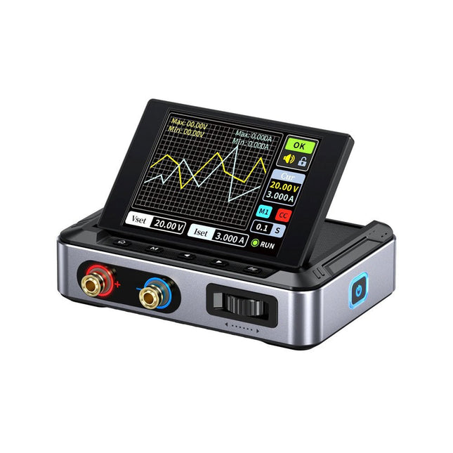
FNIRSI FNIRSI DPS150 DC-voeding (150 W)
De FNIRSI DPS150 is een krachtige, instelbare DC-voeding met een USB-C-ingangsinterface en meerdere voedingsmodi, waardoor een nauwkeurige aanpassing van de uitgangsspanning (0-30 V) en stroom (0-5 A) mogelijk is. Het biedt een efficiënte, laag verbruik en stabiele output, uitgerust met meerdere veiligheidsbeschermingsfuncties, waaronder overspanning, overstroom, overbelasting, oververhitting en omgekeerde verbinding. Het kan flexibel worden toegepast op de seriële verbinding van meerdere apparaten, met een rijke en gebruiksvriendelijke weergave en bediening, een compact en draagbaar ontwerp en voldoet aan verschillende toepassingsbehoeften. Kenmerken 30 V, 5 A, 150 W variabel gelijkstroomvermogen met 0,01 V, 0,001 A precisie, CC/CV-modi en <20 mV rimpel om gevoelige elektronica te beschermen. Ondersteunt pc-, QC- en DC-ingangen met programmeerbare uitgangen en 6 vooraf ingestelde spannings-/stroominstellingen. Compatibel met 4 mm banaanstekkers, U-vormige aansluitingen en koperdraden voor diverse apparatuur. 8 veiligheidsmechanismen, waaronder bescherming tegen overspanning, stroom, kortsluiting en oververhitting. 2,8-inch HD IPS-scherm met 90° flip-, numerieke en curve-displays voor eenvoudige monitoring. Klein, ruimtebesparend ontwerp voor gebruik in laboratoria, reparaties en doe-het-zelf-projecten. Specificaties Ingangsspanning 5~32 V DC Ingangsstroom 100 mA-5 A Uitgangsspanning 0-30 V Uitgangsstroom 0~5 A Uitgangsvermogen 0-150 W Input way PD-snellader QC snellader Powerbank DC-voedingsadapters Bedrijfsomgeving 0-40°C Belastingsregeling 0,49% Efficiëntie bij volledige belasting 96,30% Display 2,8 inch (320 x 240) Afmetingen 106 x 76 x 28 mm Gewicht 178 g Inbegrepen 1x DPS150 voeding 2x Krokodillenklemdraden (zwart en rood) 1x Micro-USB-kabel 1x Manual Downloads Manual Firmware V0.0.1
€ 59,00
-

Rigol Rigol DG2052 Function/Arbitrary Waveform Generator (50 MHz)
Highlights Output Frequency (Sine): 50 MHz Output Frequency (Square): 15 MHz Channels: 2 Arbitrary Waveform Length: 16 Mpts Kenmerken Unique SiFi II (Signal Fidelity II) technology: generate the arbitrary waveforms point by point; recover the signal without distortion; sample rate accurate and adjustable; jitter of all the output waveforms (including Sine, Pulse, etc.) as low as 200 ps 16 Mpts memory depth per channel for arbitrary waveforms Standard dual-channel with the same performance, equivalent to two independent signal sources High frequency stability: ±1 ppm; low phase noise: -105 dBc/Hz Built-in high-order harmonic generator (at most 8-order harmonics) Built-in 7 digits/s, 240 MHz bandwidth full featured frequency counter Up to 160 built-in arbitrary waveforms, covering the common signals in engineering application, medical electronics, auto electronics, math processing, and other various fields Sample rate up to 250 MSa/s, vertical resolution 16 bits Arbitrary waveform sequence editing function available; arbitrary waveforms also can be generated through the PC software Various analog and digital modulation functions: AM, FM, PM, ASK, FSK, PSK, and PWM. Standard waveform combine function, capable of outputting specified waveforms combined with the basic waveforms Standard channel tracking function, when enabled, all the parameters of both channels are updated based on users' configurations Standard interface: USB Host&Device and LAN (LXI Core 2011 Device); USB-GPIB function supported 4.3'' TFT Inbegrepen 1x Rigol DG2052 Function/Arbitrary Waveform Generator 1x Power cord 1x USB cable
€ 652,19


