
Zoekresultaten voor "fahrzeugdiagnose OR mit OR obd OR 2"
-

Elektor Digital Elektor Novembre/Décembre 2021 (PDF)
TRAITEMENT D'IMAGES AVEC LE KIT JETSON NANO DE NVIDIA2e partie : reconnaissance d'imagesELEKTOR JUMPSTARTER – DU NOUVEAUCampagnes à venirTRACEUR GPS À CODE SOURCE OUVERTTraccar cartographie les déplacements de véhicules, sans recours à un serveur tiers du nuageTESTEUR MULTIFONCTION LCR-T7 DE JOY-ITTest de semi-conducteurs passifs, discrets et de télécommandes IRSYNTHÉTISEUR DE BRUITDu bruit à la musique avec le PRBSynth1DÉMARRER EN ÉLECTRONIQUE…Easier than Imagined! ... Continuing with the CoilVOYAGE DANS LES RÉSEAUX NEURONAUX (2E PARTIE)Les neurones logiquesPROBLÈMES DE SÉCURITÉ ? COMBATTEZ LE FEU PAR LE FEU !Extension à mémoire analogique, protégée par ampoule de flash, pour la boîte à témoin d'effractionKIT DU LCR-MÈTRE 2 MHZ D'ELEKTORBALISES BLUETOOTH : LA PRATIQUEGéolocalisation intra murosC PROGRAMMING ON RASPBERRY PIExtrait : communiquer par Wi-FiTEST DE PRÉCONFORMITÉ CEM POUR UN PROJET ALIMENTÉ EN COURANT CONTINUPartie 2 : le matériel et son utilisationPROPELLER 2 DE PARALLAX (5)La fonction de « broche intelligente »MODBUS SANS FIL (PARTIE 1)Matériel et programmationJUNIOR COMPUTEREn forme après 40 ans de sommeilCONSTRUIRE SON PROPRE ÉTALONNEUR DE HAUTE PRÉCISION−10 V à +10 V, 0 à 40 mA, 0,001 %ARDUINO NANO RP2040 CONNECT EN DÉTAILRaspberry Pi RP2040 + Wi-Fi + BluetoothLE CORPS PHYSIQUE DE L'INTELLIGENCE ARTIFICIELLEPROJET 2.0corrections, mises à jour et courriers des lecteursCRÉATION D'INTERFACES GRAPHIQUES EN PYTHON AVEC GUIZEROInstallez la bibliothèque Python guizero et créez vos propres interfaces graphiques.KIT DE MESURE DU CO2 POUR SALLE DE CLASSEMontage à base d'ESP8266, conçu par l'Université des Sciences Appliquées d'Aix-la-ChapelleMK484, RADIORÉTRO PO/GO...Toujours le plaisir de construire !60 ANS D'ELEKTORQue la lumière soit !HEXADOKUThe Original Elektorized Sudoku
€ 10,95
-

Elektor Digital Elektor 05-06/2026 (PDF) DE
Diese Ausgabe steht allen GOLD- und GREEN-Mitgliedern auf der ElektorMagazine-Website zum Download bereit! Sie sind noch kein Mitglied? Hier klicken! PbMonitor v2.0 – UpdateBatterieüberwachung mit verbessertem Analogdesign Audio-LatenzmessungEigenständiges Werkzeug zur Bewertung von Fehlern und Latenzen bei der Audioübertragung Rechtecksignal vs. Bode-DiagrammÜberprüfung der Leistungsfähigkeit eines Audiogeräts embedded world 2026 Clever coden mit KIKI in der Softwareentwicklung für Elektroniker Audioanalyser QA403Bezahlbare Präzision für Audio-Profis und -Hobbyisten EasyGimbalAutonomes Kamera-Tracking mit KI, Schrittmotor und Servo Sigfox-Breakout-Board (Teil 2)Nachrichten senden SchaltungsschutzÜberspannungen mit TVS-Dioden beherrschen Neue Ansätze für BatterieprüfungenEine neue Ära der Diagnostik AudiotronicsEin erster Vorverstärker CANopenTermEin Open-Source-Werkzeug für CAN – für Maker und Ingenieure Stabilisierung von Operationsverstärkernbei kapazitiver Last Projekt 2.0Korrekturen, Aktualisierungen und Leserbriefe SignalkonditionierungTipps und Tricks zur Anpassung von Spannungsbereichen TDR-Aufsatz für OszilloskopeLängenmessung, Kurzschluss, Fehlanpassung: Kabel mit Reflexionen messen! Aus dem Leben gegriffenLED It Be Lautsprecher-Oszillator und ResonanztesterEin experimentelles Projekt für Ihre Lautsprecher Elektor-Community-Tipps zu Test und Messung ESP32-Audio-Transceiver-Board (Teil 5)Audioverarbeitung und Fernsteuerung 2026: Eine KI-OdysseeKI hat ein Kontextproblem Batteriespeicher für BalkonkraftwerkeKleine Akkus mit großer Wirkung
€ 11,90
-

Elektor Academy Pro Raspberry Pi Pico with MicroPython (programmeercursus)
Deze complete microcontroller-programmeercursus op basis van de Raspberry Pi Pico bevat een leerboek, een componentenkit, praktische projecten en een uitgebreide online cursus met simulaties. Ideaal om embedded systems stap voor stap te leren programmeren in MicroPython via een praktische hands-on aanpak. Een praktische introductie tot embedded systems met de Raspberry Pi Pico Deze cursus is ontworpen voor beginners in embedded systems die op zoek zijn naar een gestructureerde en voorbeeldgerichte start. Een kit met LED’s en weerstanden, schakelaars, sensoren en actuatoren, displays, een breadboard en draden is inbegrepen. Deze worden in de cursus gebruikt om voorbeeldtoepassingen te demonstreren. Er is geen voorkennis van Arduino of embedded ontwikkeling vereist. Elke sectie bevat praktische voorbeelden en mini-projecten om belangrijke concepten te versterken en verdere verkenning te stimuleren. Aan het einde van de cursus kunt u niet alleen de voorbeelden reproduceren, maar ook uitbreiden met uw eigen ideeën en toepassingen. Wat leert u? Microcontrollerprogrammering in MicroPython met de Raspberry Pi Pico met behulp van de Thonny IDE Werken met digitale I/O, knoppen en encoders uitlezen, LED’s en relais aansturen Analoge ingangen, spanningen en sensoren uitlezen Genereren van analoge uitgangssignalen en PWM Gebruik van seriële communicatie zoals UART, I²C en SPI om displays aan te sturen en digitale sensoren en SD-kaarten uit te lezen Tijdbeheer Werken met interrupts Realtime sensorinput en besturing via knoppen, LED’s en displays Aansturen van actuatoren zoals relais en servomotoren Voor wie is dit? Studenten en zelflerenden die embedded systems willen ontdekken Makers en IoT-enthousiastelingen die hun hardwarevaardigheden willen verbeteren Docenten en trainers die kant-en-klaar lesmateriaal zoeken Wat zit er in de doos? Toegang tot de volledige cursus op het Elektor Academy Pro leerplatform Raspberry Pi Pico microcontrollerboard + USB-kabel Boek: Programming Microcontrollers in MicroPython Downloadbare projectbestanden voor elke module Componentenkit: 2× LED, rood, 5 mm LED, groen, 5 mm 3× weerstand, 470 Ω, 0,25 W LDR Potentiometer, 10 kΩ, lineair Drukknop Rotary encoder module Relaismodule DHT22 temperatuur- en vochtigheidssensor TM1637-compatibel 4-digit 7-segment display MPU-6050 IMU met headers SSD1306-compatibel I²C OLED display Micro SD-kaartadapter met header Buzzer SG90 micro servo ILI9341-compatibel SPI 240×320 TFT display 20× jumper wires Breadboard Alle programmeercursussen (en verschillen in inhoud) Cursus Arduino Raspberry Pi Pico with Arduino C/C++ ESP32 with Arduino C/C++ Raspberry Pi Pico with MicroPython ESP32 with MicroPython Online cursus Access to Arduino Course Access to Pico with Arduino C/C++ Course Access to ESP32 with Arduino C/C++ Course Access to Pico with MicroPython Course Access to ESP32 with MicroPython Course Board Uno R3 Raspberry Pi Pico ESP32 Raspberry Pi Pico ESP32 Boek Programming Microcontrollers in C/C++ Using Arduino Programming Microcontrollers in C/C++ Using Arduino Programming Microcontrollers in C/C++ Using Arduino Programming Microcontrollers in MicroPython Programming Microcontrollers in MicroPython Kit 40-delige componenten-kit 40-delige componenten-kit 40-delige componenten-kit 40-delige componenten-kit 40-delige componenten-kit
€ 69,95
Leden: € 62,96
-

Elektor Digital Das Sigfox-Praxisbuch (PDF)
Im vorliegenden Buch wird das weltweit verbreitete 0G-Netzwerk Sigfox zunächst detailliert vorgestellt. Danach wird auf der Basis eines leistungsfähigen Arduino-Sigfox-Boards eine universelle Sigfox-Test-, Mess- und Simulations-Plattform hardwaremäßig entwickelt und softwaremäßig betrieben. Diese Sigfox-Feldstation stellt dem Anwender eine Vielzahl von Möglichkeiten zur Verfügung: Sensoren, Aktoren und Displays inkl. GPS-Modul und Solargenerator. Alle Schaltungsteile (inkl. den 3D-Plott-Vorlagen für ein passendes Stationsgehäuse) und sämtlichen Softwaremodule werden offen gelegt, so dass der Leser damit weitere Sigfox-Feldstationen nach seinen eigenen Vorstellungen und Bedürfnissen entwickeln und problemlos einsetzen kann. Die Visualisierung, Auswertung und Speicherung der erfassten Felddaten wird anhand eines Freeware Dashboard Programms, mit Schnittstelle zu Google Maps, ausführlich beschrieben. Themenauswahl: Industrie 4.0, Internet of Things, 0G-Netzwerke Das Sigfox-Netzwerk: Übertragungstechnik, Uplink/Downlink, das Monarch-Konzept, Geolokalisierung, Sigfox-Atlas-Konzept Das Sigfox-Backend, die Callbacks und die REST-API Aufbau der universellen Sigfox-Test-, Mess- und Simulations-Plattform auf der Basis des Arduino-Sigfox-Moduls MKR FOX1200 Die grundlegende Betriebssoftware für alle Komponenten Die Arduino-Sigfox-Bibliothek und der Sigfox-Betrieb – Anmeldung bei der Sigfox-Cloud, Aussendung von Mess- und Zustandswerten Die Sigfox-Callbacks – Der Datentransfer von der Sigfox-Cloud zum Anwender: E-Mails, Mess- und Zustandswerte, GeoLoc-Daten Die individuelle Gestaltung von Anwender-Dashboards Hardwareerweiterungen: HMI-Display, Thermoelementverstärker, Multichannel-Gassensor, Feinstaubsensor, GPS-Modul und vieles mehr Kommerzielle Sigfox-Stationen
€ 39,80
Leden: € 35,82
-

OWON OWON XDG2035 2-ch Arbitrary Waveform Generator (35 Mhz)
The 2-channel OWON XDG2035 is a function/waveform generator that can generate signals with a maximum frequency of 35 Hz. The generator has a resolution of 1 µHz and a sample rate of 500 MSa/s.The OWON XDG2035 is capable of generating 6 standard waveforms and 150 arbitrary waveforms. With the included software you can write advanced functions up to 10 million points. Waveforms can be saved to the function generator's internal memory using a PC via USB or LAN.The OWON XDG2035 also supports SCPI commands and LabView. The function generator has an integrated high-quality frequency counter, which can operate from 100 to 200 MHz.Features Max. 35 MHz frequency output 500 MSa/s Sample rate, Vertical resolution 1μHz 14 bits Vertical Resolution, 10 Marb waveform length Comprehensive waveform output: 6 basic waveforms,and 150 built-in arbitrary waveforms Comprehensive modulation functions: AM, FM, PM, FSK, 3FSK, 4FSK, PSK, OSK, ASK, BPSK, PWM, Sweep, and Burst High-accuracy frequency counter integrated, supported range 100-200 MHz SCPI and LabVIEW supported 7 inch multi-touch screen (800 x 480 pixels) Specifications Channel 2 Frequency Output 35 MHz Sample Rate 500 MSa/s Vertical Resolution 14 bits Waveform Standard Waveform sine, square, pulse, ramp, noise, and harmonic Arbitrary Waveform exponential rise, exponential fall, sin(x)/x, step wave, and others, total 150 built-in waveforms, and user-defined arbitrary waveform Frequency (resolution 1 μHz) Sine 1 μHz-100 MHz Square 1 μHz ~ 30 MHz Pulse 1 μHz ~ 25 MHz Ramp 1 μHz ~ 3 MHz Noise (-3 dB, typical) 100 MHz Arbitrary Waveform 1 μHz ~ 15 MHz Harmonic 1 μHz ~ 50 MHz Accuracy ±2ppm, 25°C ±5°C Waveform Length 2 points - 10M points Amplitude Into 50Ω load 1mVpp ~ 10Vpp (≤25 MHz); 1mVpp ~ 5Vpp (≤60 MHz); 1mVpp ~ 2.5Vpp (≤100 MHz) Modulation Type AM, DSB-AM, FM, PM, ASK, FSK, PSK, BPSK, QPSK, 3FSK, 4FSK, OSK, PWM, SUM Frequency Counter Function Frequency, period, +width, -width, +duty, and -duty Frequency Range 100 ~ 200 MHz Frequency Resolution 7 digits Input/Output Input mode frequency counter, external modulation input, external trigger input, internal clock output, external reference clock input/output Communication Interface USB Host, USB Device, LAN, RS232 (optional) Mechanical specifications Dimensions 340 x 177 x 90 mm Weight 2.3 kg Included 1x OWON XDG2035 1x Power Cord 1x CD-ROM 1x Quick start guide 1x USB Cable 1x BNC-BNC Cable DownloadsQuick Guide
€ 339,00
-

OWON OWON DGE3062 2-kanaals Arbitraire Golfvormgenerator (60 MHz)
The OWON DGE3062 is a 14-bit function generator with a bandwidth of 60 MHz. It has 5 basic waveforms, 160 built-in arbitrary waveforms and the following comprehensive modulation functions: AM, FM, PM, PWM, FSK, 3FSK, 4FSK, PSK, ASK, BPSK, OSK, DSBAM, QPSK, SUM, sweep, Burst. Kenmerken Max. 60 MHz frequency output, 300 MSa/s Sample rate 14 bits Vertical Resolution, 100K Arb waveform length Comprehensive waveform output: 5 basic waveforms, and 160 built-in arbitrary waveforms Comprehensive modulation functions: AM, FM, PM, PWM, FSK, 3FSK, 4FSK, PSK, ASK, BPSK, OSK, DSBAM, QPSK, SUM, sweep, Burst SCPI and LabVIEW supported 3.6 inch LCD (480 x 272 pixels) Specificaties Channel 2 Frequency Output 60 MHz Sample Rate 300 MSa/s Vertical Resolution 14 bits Waveform Standard Waveform Sine, square, pulse, ramp, noise Arbitrary Waveform Exponential rise, exponential fall, sin(x)/x, step wave, and others, total 160 built-in waveforms Frequency (resolution 1 μHz) Sine 1 μHz-60 MHz Square 1 μHz ~ 20 MHz Pulse 1 μHz ~ 20 MHz Ramp 1 μHz ~ 2 MHz Noise 20 MHz (-3 dB, typical) Arbitrary Waveform 1 μHz ~10 MHz Arbitrary Waveform Length 2 points – 100K points Sample Rate 300 MSa/s Amplitude Into 50Ω load 1mVpp ~ 10Vpp (≤10Hz), 1mVpp ~ 5Vpp (≤60 MHz) DC Offset Range (AD+DC ±(10 Vpk – Amplitude Vpp/2) high resistance±(5 Vpk – Amplitude Vpp/2) 50 Ω DC offset resolution 1 mV or 4 digits Load Impedance 50 Ω (typical) DC offset Accuracy ±(1% of |setting| + 1 mV + amplitude Vpp * 0.5%) Modulation Type AM,FM, PM, PWM, FSK, 3FSK, 4FSK, PSK, ASK, BPSK, OSK, DSB-AM, QPSK, SUM, Sweep, Burst Frequency Counter Function Frequency, period Frequency Range 100 MHz ~ 100 MHz Frequency Resolution 6 digits Input/Output Display 3.6” LCD Input mode External modulation input, external trigger input, external reference clock input/output Communication Interface USB Host, USB Device Mechanical specifications Dimensions (W x H x D) 200 x 92 x 157 mm Weight 0.8 kg Inbegrepen 1x OWÒN DGE3062 Arbitraire Golfvormgenerator 1x Power Cord 1x Quick Guide 1x USB Cable 1x Q9 Cable 1x BNC to Alligator Clip Downloads Quick Guide Manual Software
€ 212,50
-
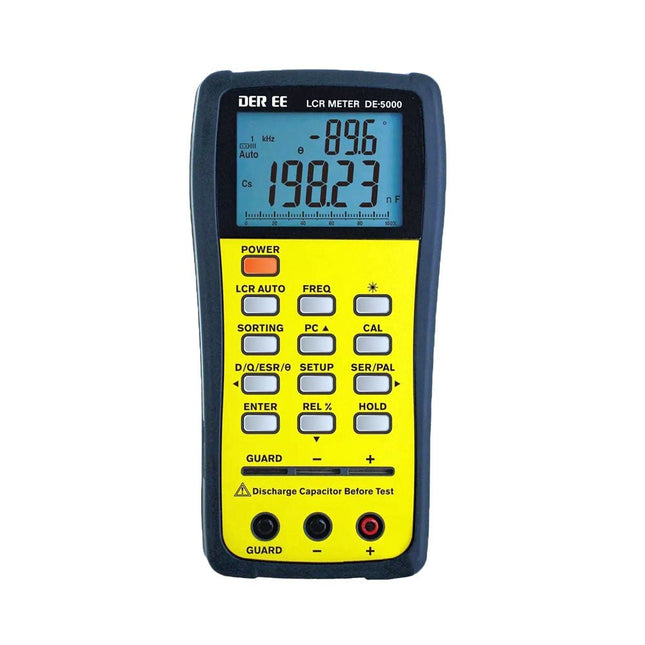
DER EE DER EE DE-5000 LCR-meter (100 kHz)
De DE-5000 is een slimme, zeer nauwkeurige, flexibele en gebruiksvriendelijke draagbare LCR-meter. Hij beschikt over automatische LCR-check, 4-draads Kelvin-meting, een backlit display met 19999 / 1999 counts, meerdere meetmodi, en instelbare testfrequenties (100 Hz, 120 Hz, 1 kHz, 10 kHz of 100 kHz). De DE-5000 LCR-meter is een handig hulpmiddel voor ingenieurs of technici. Kenmerken Automatische L.C.R. check Ls/Lp/Cs/Cp/Rs/Rp/DCR met D/Q/?/ESR meting 4-draads Kelvin-meting 19999 / 1999 counts display Achtergrondverlichting Relatieve modus Serieel/parallel modus Componenten sorteerfunctie Indicatie bij 'accu bijna leeg' Automatische power-off Specificaties Test frequentie 100 Hz / 120 Hz / 1 kHz / 10 kHz / 100 kHz Weerstand bereik 20.000 ? – 200,0 M? DCR bereik 200.00 ? – 200.0 M? Capaciteit bereik 200.00 pF – 20.00 mF Inductie bereik 20.000 ?H – 2.000 KH Display (backlit LCD-scherm) 19999 / 1999 counts Instelbare tolerantie ±0,25%, ±0,5%, ±1%, ±2%, ±5%, ±10%, ±20% Voeding 9 V accu Afmetingen 188 x 95 x 52 mm Gewicht 350 g (exclusief accu) Inbegrepen DE-5000 LCR-meter Meetconnector met krokodillenklemmen (TL-21) AC/DC-adapter Guard kabeltje (TL-23) TL-22 SMD pincetten 9 V accu Draagtas Handleiding Downloads Datasheet
€ 192,39
-

Elektor Digital Elektor 05-06/2023 PDF (DE)
Diese Ausgabe steht allen GOLD- und GREEN-Mitgliedern auf der ElektorMagazine-Website zum Download bereit! Sie sind noch kein Mitglied? Hier klicken! Super-Servo-TesterBis zu vier Servos einzeln oder eingebaut testen Analoge Signale und der MikrocontrollerADCs, DACs, Strommessung und mehr embedded world 2023 Sub-Nyquist-Sampling in der PraxisHöhere Frequenzen mittels Unterabtastung sicher erfassen Hier Android-Smartphone, dort ESP32?Praxisprojekt mit der Android WiFi-API Aktives 1-kHz-Filter für VerzerrungsmessungenBessere Messungen durch Optimierung des Messsignals Aller Anfang...muss nicht schwer sein: Wir multivibrieren weiter! Projekt 2.0Korrekturen, Updates und Leserbriefe Das neue I3C-ProtokollWürdiger I2C-Nachfolger oder viel Rauch um Nichts? BlueRC: IR-Fernsteuerung mit Smartphone und ESP32Anpassungsfähig und universell Mikrocontroller-Dokumentationen verstehenTeil 2: Register und Blockschaltbilder Automatisierung der Prüf- und MesstechnikProgrammieren von Prüfgeräten, damit sie tun, was Sie wollen Infografik: Messen und Testen Überspannungsschutz für sicheren BetriebTransientenschutz für nicht-isolierte DC/DC-Leistungsmodule Mess- und Prüfgeräte von WihaInstallationstester und Messgeräte, auf die Sie sich verlassen können Automatisierung von Tests und Zusammenarbeit bei Testergebnissen Aus dem Leben gegriffenElektronik auf hohem Niveau EnergieloggerEnergie messen und aufzeichnen Aufgebaut: Das 4tronix M.A.R.S. Rover Kit Parkscheibe mit E-Paper DisplayEin innovativer digitaler Ersatz eCO2-Telegram-BotLuftqualitätsmessung mit Telegram-Anbindung Hinter den Kulissen von High-End-Audio im EigenbauElektor-Ingenieur Ton Giesberts im Interview über die hohe Kunst des Analogdesigns Das besondere ProjektEs gibt noch viel zu tun! RFID-Tag lesen und RFID-TürschlossProjektbeispiele aus dem Arduino-Experimentierpaket von Elektor Oszilloskop-Stromsonde für HFHochfrequenz-Strommessung leichtgemacht Nichts für Anfänger – Makerfabs 6 DOF Robot ArmMit Raspberry Pi Pico und MicroPython Generative KIWer hat das eigentlich gemacht? Hexadoku
€ 11,90
-
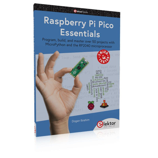
Elektor Publishing Raspberry Pi Pico Essentials
Program, build, and master over 50 projects with MicroPython and the RP2040 microprocessor The Raspberry Pi Pico is a high-performance microcontroller module designed especially for physical computing. Microcontrollers differ from single-board computers, like the Raspberry Pi 4, in not having an operating system. The Raspberry Pi Pico can be programmed to run a single task very efficiently within real-time control and monitoring applications requiring speed. The ‘Pico’ as we call it, is based on the fast, efficient, and low-cost dual-core ARM Cortex-M0+ RP2040 microcontroller chip running at up to 133 MHz and sporting 264 KB of SRAM, and 2 MB of Flash memory. Besides its large memory, the Pico has even more attractive features including a vast number of GPIO pins, and popular interface modules like ADC, SPI, I²C, UART, and PWM. To cap it all, the chip offers fast and accurate timing modules, a hardware debug interface, and an internal temperature sensor. The Raspberry Pi Pico is easily programmed using popular high-level languages such as MicroPython and or C/C++. This book is an introduction to using the Raspberry Pi Pico microcontroller in conjunction with the MicroPython programming language. The Thonny development environment (IDE) is used in all the projects described. There are over 50 working and tested projects in the book, covering the following topics: Installing the MicroPython on Raspberry Pi Pico using a Raspberry Pi or a PC Timer interrupts and external interrupts Analogue-to-digital converter (ADC) projects Using the internal temperature sensor and external temperature sensor chips Datalogging projects PWM, UART, I²C, and SPI projects Using Wi-Fi and apps to communicate with smartphones Using Bluetooth and apps to communicate with smartphones Digital-to-analogue converter (DAC) projects All projects given in the book have been fully tested and are working. Only basic programming and electronics experience is required to follow the projects. Brief descriptions, block diagrams, detailed circuit diagrams, and full MicroPython program listings are given for all projects described. Readers can find the program listings on the Elektor web page created to support the book.
€ 39,95
Leden: € 35,96
-

Elektor Publishing MIT App Inventor for AI and IoT
Build Smart Applications with Raspberry Pi, Arduino, and ESP32 Discover how easy and exciting mobile app development can be with MIT App Inventor. This hands-on guide takes you from basic concepts to building real-world mobile applications using a simple visual programming approach—no prior coding experience required. You will create IoT and AI-powered apps for Android devices and explore how App Inventor can also be used with iPhones and iPads. Connect your applications to platforms such as Arduino UNO R4 WiFi, ESP32, Raspberry Pi Pico (2)W and Raspberry Pi 5, enabling you to build smart, connected systems. Inside the book, you will learn how to: Build interactive apps using buttons, images, sound, and multimedia Create text-to-speech and speech-recognition applications Develop camera-based and location-aware (GPS) apps Design useful tools such as calculators and educational apps Work with smartphone sensors like accelerometers and light sensors Build AI-powered applications, including voice assistants and image-generation features Send and receive messages, and create communication-based apps Connect mobile apps to hardware using Wi-Fi and Bluetooth Control real devices such as LEDs, motors, and sensors Designed for beginners, students, and hobbyists, this book focuses on learning by doing. By the end, you will have the skills and confidence to create your own innovative applications that interact with both the digital and physical worlds. Start building and turning your ideas into reality.
€ 44,95
Leden: € 40,46
-
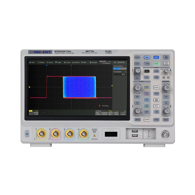
Siglent Siglent SDS2204X Plus 4-ch Oscilloscope (200 Mhz)
Siglent's SDS2000X Plus series Digital Storage Oscilloscopes are available in bandwidths of 100 MHz, 200 MHz, and 350 MHz, have a maximum sample rate of 2 GSa/s, a maximum record length of 200 Mpts/ch, and up to 4 analog channels + 16 digital channels mixed-signal analysis ability. The SDS2000X Plus series employs Siglent’s SPO technology with a maximum waveform capture rate of up to 120,000 wfm/s (normal mode, up to 500,000 wfm/s in Sequence mode), 256-level intensity grading display function plus a color temperature display mode. It also employs an innovative digital trigger system with high sensitivity and low jitter. The trigger system supports multiple powerful triggering modes including serial bus triggering. History waveform recording, Sequence acquisition, Search and Navigate functions allow for extended waveform records to be captured, stored, and analyzed. An impressive array of measurement and math capabilities, options for a 50 MHz waveform generator, as well as serial decoding, mask test, bode plot, and power analysis are also features of the SDS2000X Plus. A 10-bit acquisition mode helps to satisfy applications that require more than 8-bit resolution. The large 10.1’’ capacitive touch screen supports multi-touch gestures, while the remote web control, mouse and external keyboard support greatly improve the operating efficiency of the SDS2000X Plus. Features 100 MHz, 200 MHz, 350 MHz (upgradable to 500 MHz) models Real-time sampling rate up to 2 GSa/s Record length up to 200 Mpts Serial bus triggering and decoder, supports I²C, SPI, UART, CAN, LIN, CAN FD, FlexRay, I²S and MIL-STD-1553B Provide 10 bit mode, Vertical and Horizontal Zoom Capacitive touch screen supports multi-touch gestures Siglent SDS2000X Plus Oscilloscopes SDS2102X Plus SDS2104X Plus SDS2204X Plus SDS2354X Plus Bandwidth 100 MHz 100 MHz 200 MHz 350 MHz Channels 2 4 4 4 Real-time sampling rate 2 GSa/s 2 GSa/s 2 GSa/s 2 GSa/s Capture rate 120,000 wfm/s 120,000 wfm/s 120,000 wfm/s 120,000 wfm/s Memory depth 200 Mpts/ch 200 Mpts/ch 200 Mpts/ch 200 Mpts/ch Included Siglent SDS2204X Plus Oscilloscope Passive probes Power cord USB cable Manual Downloads Datasheet Manual Quick guide User manual Firmware
€ 1.838,23
-
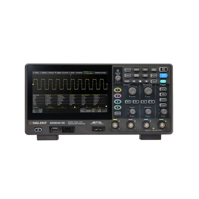
Siglent Siglent SDS814X HD 4-kanaals Oscilloscoop (100 MHz)
The Siglent SDS814X HD digital storage oscilloscope is based on 2 GSa/s, 12-bit Analog-Digital Converters and front ends with excellent noise floor performance. With a 100 MHz bandwidth, and a maximum record length of 50 Mpts, and the capability to analyze 4 analog channels alongside 16 digital channels, the SDS814X HD is perfectly suited for mixed signal analysis. Kenmerken 12-bit High Resolution 12-bit Analog-Digital Convertors with sample rate up to 2 GSa/s Front ends with 70 μVrms noise floor @ 100 MHz bandwidth 2/4 analog channels, up to 700 MHz bandwidth SPO technology Waveform capture rate up to 80,000 wfm/s (normal mode), and 500,000 wfm/s (sequence mode) Supports 256-level intensity grading and color temperature display modes. Up to 50 Mpts record length Digital trigger system Intelligent trigger: Edge, Slope, Pulse width, Window, Runt, Interval, Dropout, Pattern, Video (HDTV supported), Qualified, Nth edge, Delay, Setup/Hold time. Serial bus triggering and decoder, supports protocols I²C, SPI, UART, CAN, LIN. Segmented acquisition (Sequence) mode, dividing the maximum record length into multiple segments (up to 80,000), according to trigger conditions set by the user, with a very small dead time between segments to capture the qualifying event. History waveform record (History) function, the maximum recorded waveform length is 80,000 frames. Automatic measurements on 50+ parameters, supports statistics with histogram, track, trend, Gating measurement, and measurements on Math, History and Ref. 4 Math traces (2 Mpts FFT, addition, subtraction, multiplication, division, integration, differential, square root, etc.), supports formula editor. Abundant data analysis functions such as Search, Navigate, Counter, Bode plot and Power Analysis High Speed hardware-based Mask Test function, with Mask Editor tool for creating user-defined masks 16 digital channels (optional) 25 MHz waveform generator (optional) 7" TFT-LCD display with 1024 x 600 resolution; Capacitive touch screen supports multi-touch gestures. Interfaces include: USB Hosts, USB Device (USBTMC), LAN (VXI-11/Telnet/Socket), Pass/Fail, Trigger Out Built-in web server supports remote control over the LAN port using a web browser. Supports SCPI remote control commands. Supports external mouse and keyboard. Supports NTP. Specificaties Analog Channels 4 Bandwidth 100 MHz Vertical resolution 12-bit Sample rate (Max.) One channel mode: 2 GSa/sTwo channel mode: 1 GSa/sFour channel mode: 500 MSa/s Memory depth (Max.) One channel mode: 50 Mpts/chTwo channel mode: 25 Mpts/chFour channel mode: 10Mpts/ch Waveform capture rate (Max.) Normal mode: 80,000 wfm/sSequence mode: 500,000 wfm/s Trigger type Edge, Slope, Pulse width, Window, Runt, Interval, Dropout, Pattern, Video, Qualified, Nth edge, Delay, Setup/Hold time, Serial Serial trigger and decode (Standard) I²C, SPI, UART, CAN, LIN Measurement 50+ parameters, statistics, histogram, trend, and track supported Math 4 traces 2 Mpts FFT, Filter, +, -, x, ÷, ∫dt, d/dt, √, Identity, Negation, Absolute, Sign, ex, 10x, ln, lg, Interpolation, MaxHold, MinHold, ERES, Average. Supports formula editor Data analysis Search, Navigate, History, Mask Test, Counter, Bode plot, and Power Analysis Digital channel (optional) 16-channel; maximum sample rate up to 1 GSa/s; record length up to 10 Mpts USB AWG module (option) One channel, 25 MHz, sample rate of 125 MHz, wave length of 16 kpts, isolated output I/O 2x USB 2.0 Host, USB 2.0 Device, 10/100 M LAN, Auxiliary output (TRIG OUT, PASS/FAIL), SBUS (Siglent MSO) Probe (Standard) Passive probe PB470 for each channel Display 7 TFT-LCD with capacitive touch screen (1024x600) Inbegrepen 1x Siglent SDS814X Oscilloscope 4x Passive probe (100 MHz) PP510 1x Power cord (EU) 1x USB cable 1x Certificate of calibration 1x Quick start Downloads Datasheet Manual Programming guide
€ 586,85


